Dynamic Drop Tower Impact Testing Principles for Consolidated Battery Tubs
Dynamic drop tower testing validates consolidated battery tub impact energy absorption, preventing cell intrusion and thermal runaway under vertical shock.
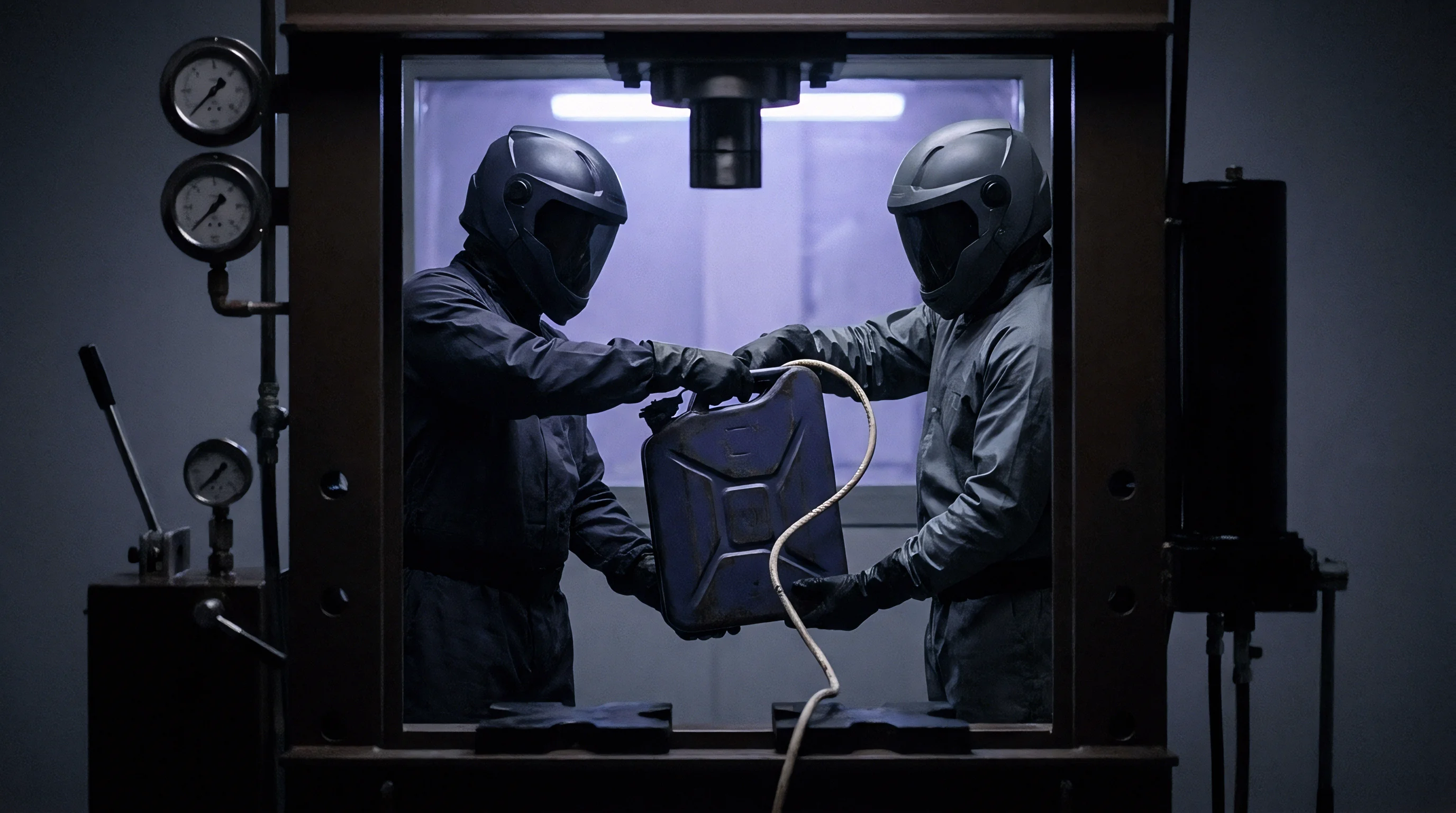

Anvil
Dynamic drop tower impact testing subjects structural battery enclosures to vertical load transfers that simulate ground-strike events. In consolidated battery tubs ~ where high-pressure die-cast aluminum or multi-material assemblies integrate the pack housing into the chassis floor ~ shock propagation determines whether the structure survives. Dropping a calibrated mass from a set height delivers controlled kinetic energy directly into the bottom plate, internal cross-members, and perimeter sills.
Drop tower testing rigs use guided mass carriages operating on ultra-low-friction rails. The energy delivered to the test tub scales linearly with total guided mass and impact height, yielding predictable velocity profiles prior to contact.

Kinetic Energy Transferred through Base Assemblies
Vertical drop rigs evaluate how a tub enclosure dissipates kinetic energy when hitting hazards beneath the floor pan. This energy converts into plastic strain within the metal, elastic stress waves across cross-members, and localized friction at bolted joints. Drop masses typically range from 200 kilograms to 1,200 kilograms, generating impact velocities between 5 meters per second and 15 meters per second.
Total energy input must match or exceed regulatory ground-impact requirements to ensure the floor panel resists severe intrusion. A 500 kilogram mass dropping from 5 meters generates roughly 24.5 kilojoules of kinetic strike energy. When the impactor hits the central floor, deformation cascades through structural web ribs into adjacent module mounting rails.
Structural pack enclosures absorb impact impulse through distributed plastic deformation rather than rigid resistance.

Impactor Profiles and Localized Intrusion Dynamics
The geometry of the drop mass head controls how force spreads across floorpan panels. Hemispherical impactors with radii between 50 millimeters and 150 millimeters concentrate energy into tight contact zones, testing localized shear resistance and puncture thresholds. Cylindrical wedges simulate linear curb strikes, inducing bending moments across parallel floor extrusions simultaneously.
Blunt planar impactors evaluate gross crushing and perimeter weld shear under broad vertical shock loads. Impactor geometry dictates whether the primary failure mode is a localized wall tear or full-frame elastic-plastic buckling.
- Structural frame cracking occurs when peak dynamic shear exceeds material yield strength across die-cast aluminum web joints.
- Floorpan penetration develops if hemispherical impactor energy concentrates on unreinforced floor regions.
- Fastener shear failure arises when lateral deceleration forces strip perimeter bolt threads under impulse loading.
- Internal structural buckle manifests when structural aluminum extrusions undergo asymmetrical axial collapse.
Mismatched drop mass values during floor impact testing lead to inaccurate intrusion profiles, risking unpredicted cell enclosure punctures in the field.

Response
High strain rates govern structural deformation during transient dynamic loading, determining consolidated tub integrity. During high-velocity drops, material properties shift away from quasi-static behavior. Aluminum alloys and structural composites show elevated yield strengths and altered ductility regimes when strain rates exceed 100 per second.
Johnson-Cook constitutive material equations capture this high strain rate behavior during dynamic crash modeling. When the drop mass impacts the tub floor, stress waves propagate through the structure at the material speed of sound, creating localized strain concentrations before global frame deflection begins.
Strain Rate Mechanics in Cast Aluminum Tubs
Yield stress increases rapidly under high-velocity displacement in high-pressure die-cast aluminum alloys. Silicon-magnesium casting alloys like AlSi10MnMg exhibit strain-rate hardening when impacted at speeds above 8 meters per second. Higher strain rates, however, reduce plastic elongation before fracture, making casting web fillets more susceptible to brittle cracking.
Automotive designers balance ultimate tensile strength against material elongation. Extruded 6005A-T6 alloy floor members provide predictable energy absorption through controlled crushing, while large-format castings maintain dimensional chassis rigidity.
Dynamic extrusion buckling absorbs peak mechanical shock before kinetic forces reach internal battery cell modules.

Internal Module Displacement Boundaries
Internal cell pack assemblies experience compressive shock waves when lower tub plates buckle. The clearance zone between the interior floor skin and the lower module mounting plane sets the allowable plastic intrusion limit. Encroaching on this zone transmits crushing forces directly into cell pouches, prismatic cans, or cylindrical array holders.
Intrusion depth limits depend on cell mechanical tolerances. Pouch cells tolerate localized lateral compression up to 5 percent of their total stack thickness before separator breakdown occurs. Prismatic aluminum cans suffer side-wall buckling when external crushing forces exceed 12 kilonewtons per cell, potentially inducing internal short circuits.
- Mount the consolidated tub assembly onto the rigid bed fixture using calibrated torque specifications for all boundary clamps.
- Raise the dynamic impact mass to the predetermined height matching the intended impact velocity profile.
- Arm the laser trigger system to synchronize high-speed optical capture with mechanical impact timing.
- Release the drop carriage to execute free-fall impact while logging high-g transducer output streams.
Floorpan cracking during drop testing often stems from localized material porosity rather than flawed structural rib geometry.

Instrumentation
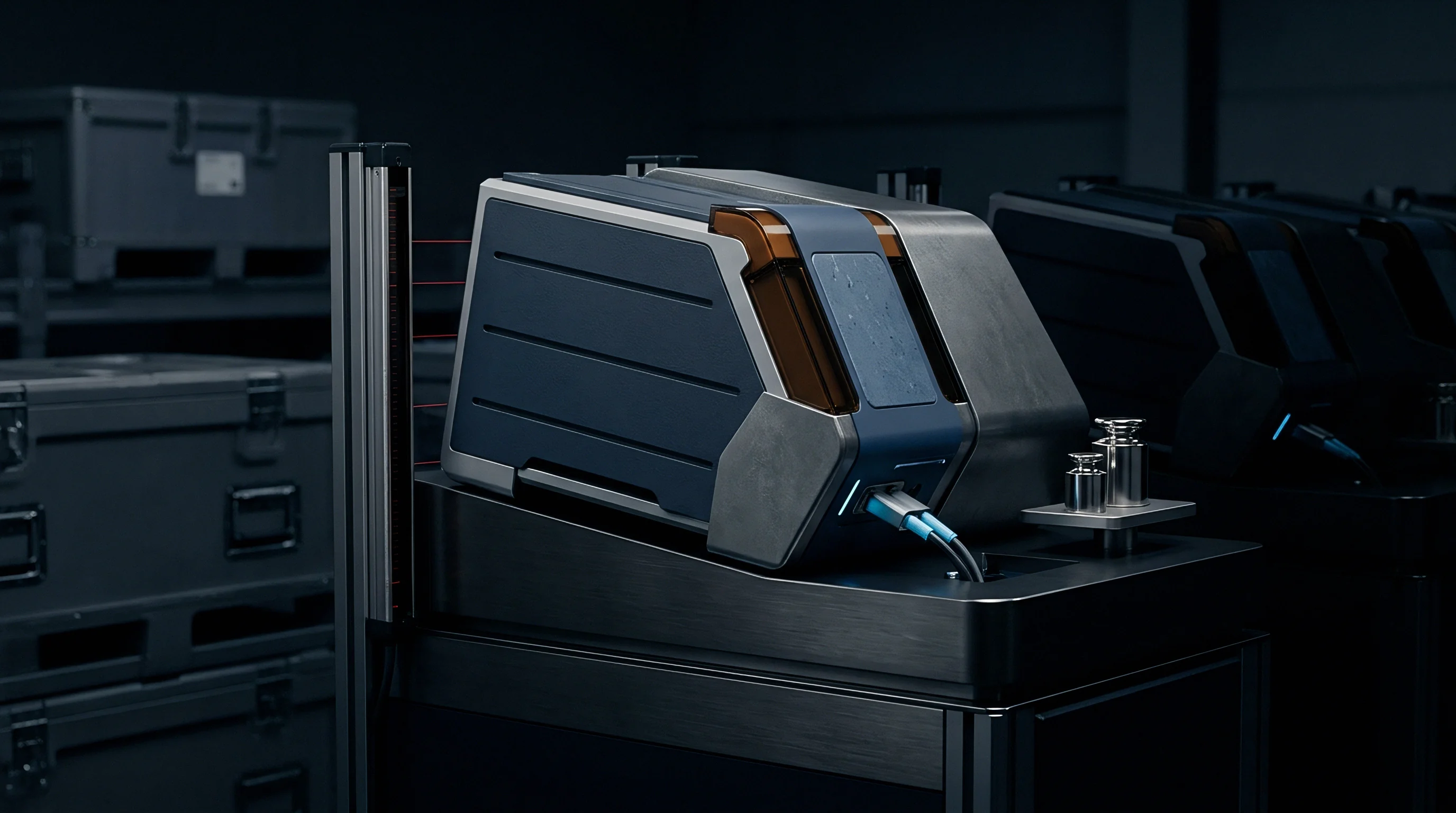
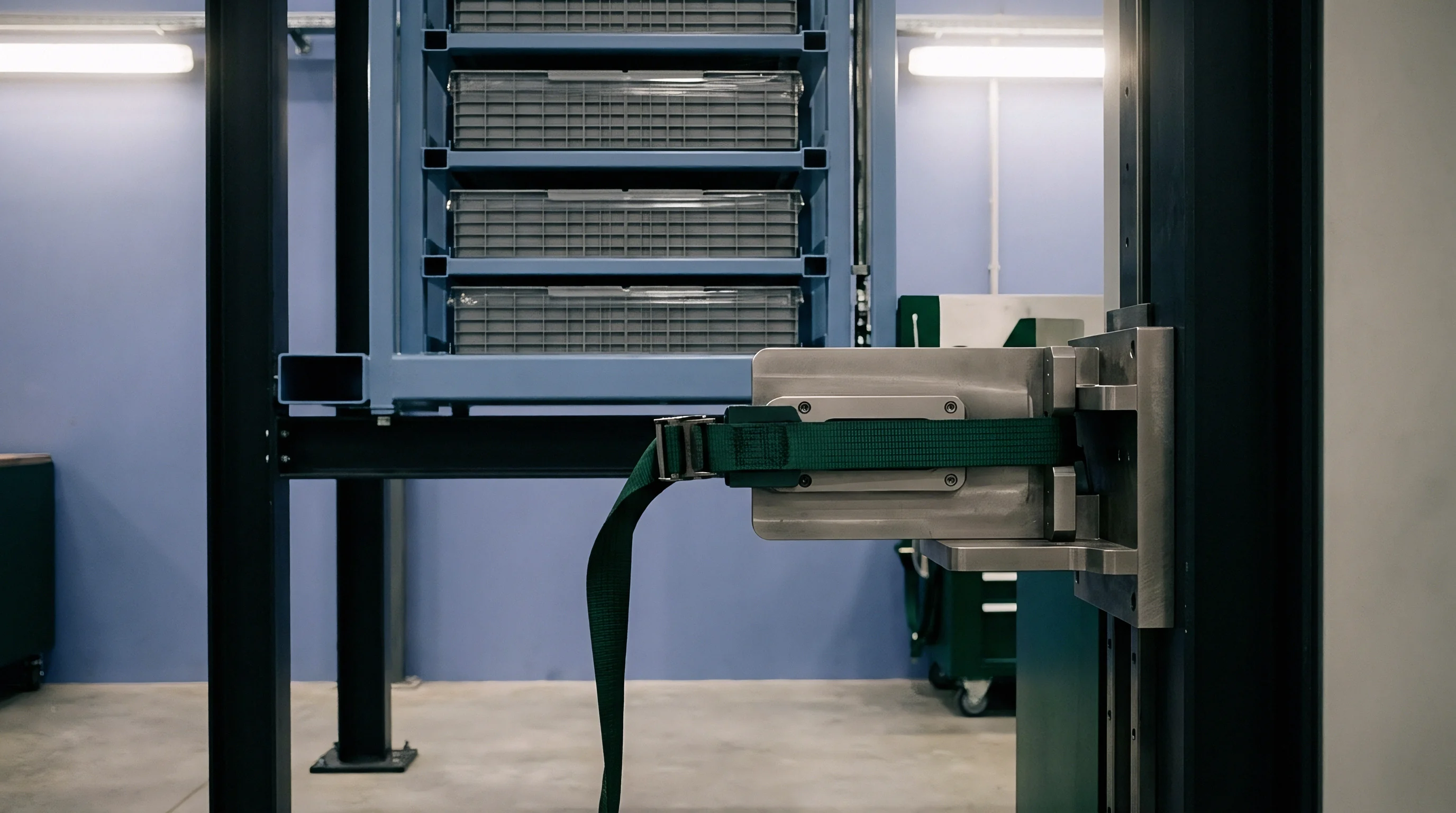
Capturing rapid transient forces requires specialized sensors capable of surviving high acceleration fields. Dynamic drop tests unfold over milliseconds, demanding microsecond sensor response and high sampling rates. Instrumenting a battery tub involves placing triaxial accelerometers, load cells, and optical tracking arrays at critical structural nodes.
Data acquisition systems must record channels simultaneously at frequencies up to 100 kilohertz to resolve peak transient shock phenomena without aliasing. Cable shielding and strain relief prevent electrical noise caused by rapid frame vibration and impact electromagnetic pulses.
Sensor Selection for High G Impact Regimes
Measuring localized strain during vertical drop strikes requires hardware with sub-millisecond response. Piezoresistive accelerometers with dynamic ranges up to 5,000g monitor structural deceleration profiles without zero-shift hysteresis. Piezoelectric load cell washers installed directly beneath support boundary clamps log reaction forces transferred to the test bed fixture.
Digital Image Correlation systems use twin high-speed cameras recording at 20,000 frames per second. Speckle patterns applied to the tub floor allow post-test software to calculate full-field surface strain distributions and micro-cracking propagation vectors.
| Sensor Modality | Primary Measurement | Dynamic Range | Sampling Frequency | Noise Susceptibility |
|---|---|---|---|---|
| Piezoresistive Accelerometer | Frame Deceleration | ±5,000 g | 100 kHz | Low |
| Piezoelectric Load Cell | Reaction Force | 0–500 kN | 50 kHz | Medium |
| Digital Image Correlation | Surface Strain Field | 0–50 % Strain | 20,000 fps | Negligible |
| Laser Displacement Sensor | Intrusion Distance | 0–300 mm | 10 kHz | Low |
Signal Processing and Channel Frequency Filtering
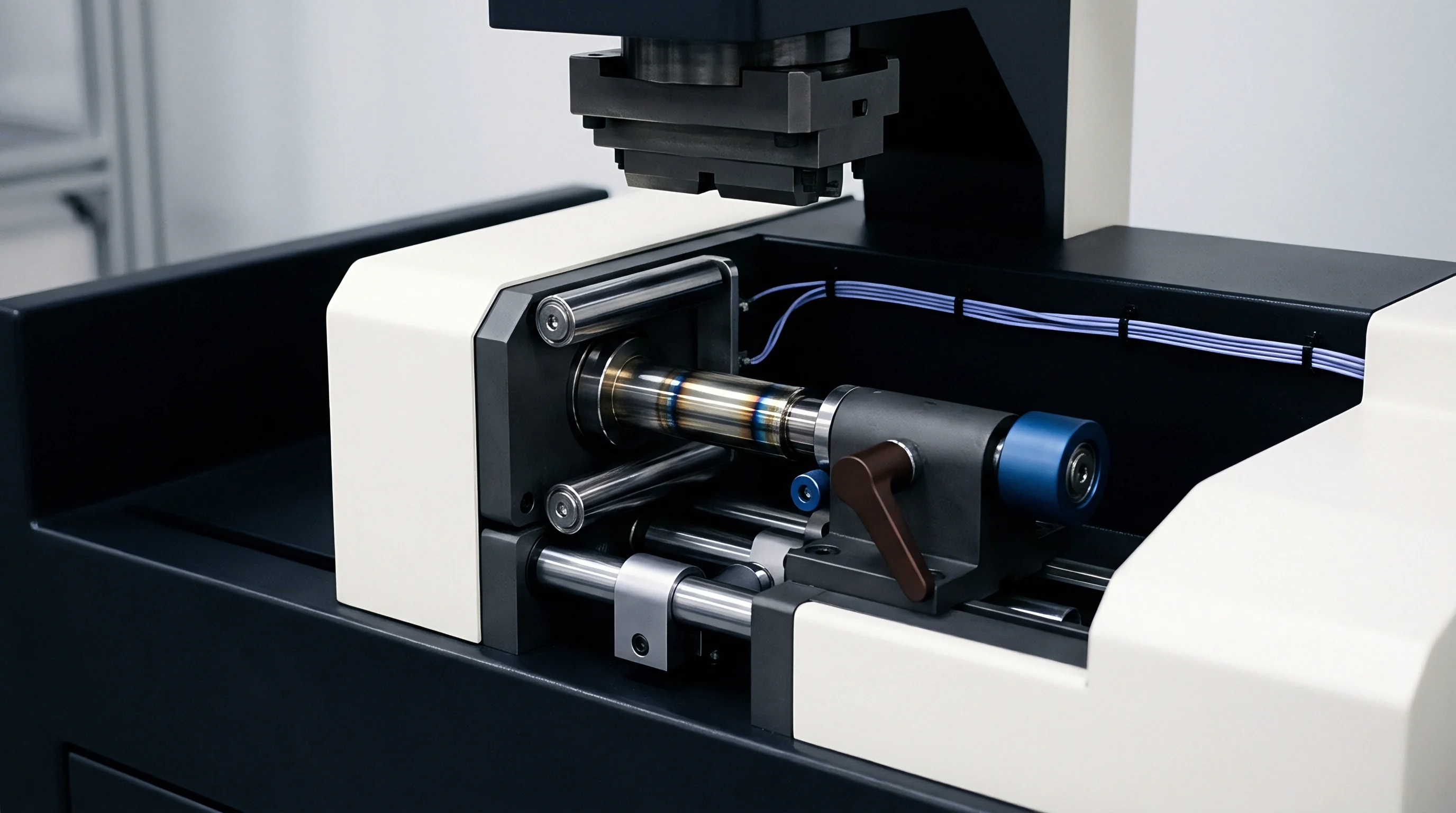
Raw acceleration output contains high-frequency mechanical noise generated by drop tower guide rails and local fixture ringing. Digital low-pass filtering according to ISO 6487 specifications smooths sensor output to reveal structural rigid-body acceleration profiles. Channel Frequency Class 60 filtering isolates gross deformation trends, while Channel Frequency Class 1000 retains structural impulse details.
ISO 6487 channel frequency class specifications dictate signal filtering bounds to prevent artificial peak shock reporting.
- Piezoresistive sensor placement near structural cast nodes isolates high-frequency mechanical shock from frame vibration.
- Sampling rate configuration set above 100 kilohertz prevents signal clipping during initial peak impact.
- Optical grid mapping applied to the tub floor facilitates high-resolution digital image correlation tracking.
- Cable anchoring protocols protect signal wires from whip-induced noise artifacts during high-acceleration drops.
Compliance under ISO 6487 Channel Frequency Class 60 mandates low-pass filtering that removes structural ringing artifacts from force trace calculations.

Mitigation
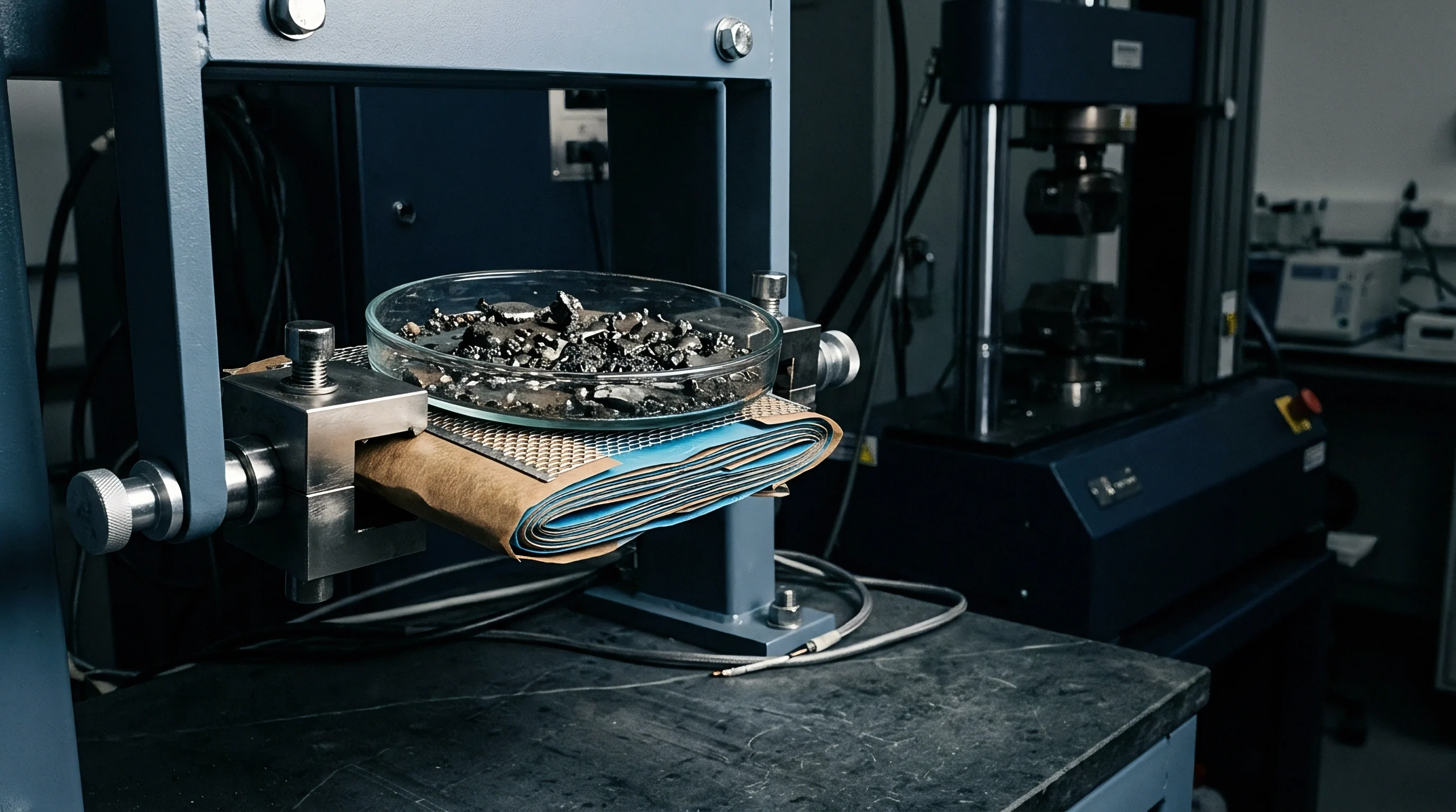
Energy dissipation architectures within consolidated underbody structures protect internal battery cells from intrusion. Tub floor engineering relies on sacrificial components designed to collapse at pre-programmed force thresholds. Incorporating composite sandwich structures, aluminum honeycomb inserts, and structural shear pins channels kinetic energy away from sensitive cell modules.
Integrated structural foam fills hollow extruded floor channels, dampening high-frequency shock waves and increasing local buckling resistance during severe impacts.

Structural Architecture and Energy Absorption Strategies
Integrating progressive crush zones into floor extrusions dissipates impact energy before the tub floor deforms. Ribbed double-wall geometries disperse point loads from hemispherical impactors into lateral shear across the main tub casting. Shear keys placed at module frame interfaces deform plastically, isolating the cell matrix from perimeter sill bending moments.
Structural adhesives bonding the lower floor plate to internal cross-members ensure uniform load transfer, preventing the localized stress concentrations that initiate metal tearing.
Structural aluminum tubs limit dynamic intrusion below 15 millimeters under a 30 kilojoule impact to preserve cell wall integrity.

Worked Calculation for Dynamic Energy Absorption
Evaluating how a cast aluminum tub deforms requires defining kinetic shock variables. Consider a drop test rig releasing a 450 kilogram mass from a height of 3.2 meters onto a consolidated tub floor pan, assuming gravitational acceleration of 9.81 meters per second squared.
Total kinetic energy at impact equals initial potential energy: 450 multiplied by 9.81 multiplied by 3.2 gives 14,126 joules, or 14.13 kilojoules. Impact velocity equals the square root of two times 9.81 times 3.2, yielding 7.92 meters per second.
If structural requirements limit maximum internal floor displacement to 25 millimeters (0.025 meters), the mean dynamic crush force required to halt the mass is total kinetic energy divided by displacement. Dividing 14,126 joules by 0.025 meters yields a mean dynamic reaction force of 565 kilonewtons. Applying a dynamic amplification factor of 1.35 to account for high strain rate stiffness raises the required peak reaction force capability of the floor structure to 762.8 kilonewtons.
- Extrusion wall thickness dictates the initial peak buckling force during underside impacts.
- Cast rib web geometry influences shear stress distribution across primary structural load paths.
- Sacrificial foam inserts absorb high-frequency kinetic pulses before frame displacement begins.
- Underbody skid plate alloys provide continuous puncture resistance against sharp drop mass shapes.
Ductile material deformation absorbs impact kinetic energy more predictably than ultra-high-strength brittle castings.


Acceptance
Verifying tub structural performance after dynamic impact requires physical inspection and electrical measurement. Pass/fail decisions depend on structural clearance metrics, containment of cell modules, and electrical isolation integrity. A successful drop test confirms that the battery tub shields modules from mechanical intrusion and prevents catastrophic thermal events.
Post-impact evaluations include holding the tested battery pack assembly in an isolated observation bay for a minimum duration to monitor thermal stability.

Regulatory Test Frameworks and Post Impact Isolation
International transport standards mandate strict structural margins after mechanical shock exposure. UN 38.3.4.4 and ECE R100.03 outline physical crush and drop requirements for vehicle-integrated battery systems. ECE R100.03 requires that underbody impact tests result in no cell containment breaches, zero coolant leakage exceeding designated thresholds, and no fires or explosions during a 6-hour monitoring window.
Electrical isolation monitoring confirms that high-voltage busbars stay insulated from the chassis enclosure. Minimum post-impact isolation resistance must remain at least 500 ohms per volt for direct current systems to prevent electrocution hazards.
| Standard Designation | Impact Energy / Velocity | Maximum Intrusion Limit | Post-Impact Hold Period | Electrical Isolation Requirement |
|---|---|---|---|---|
| ECE R100.03 | 100 kJ / 10 m/s | No Module Compression | 6 Hours | >500 Ω/V |
| UN 38.3.4.4 | Drop height 0.1–1.0 m | Zero Outer Wall Rupture | 2 Hours | >100 Ω/V |
| SAE J2464 | Variable drop mass head | Maintain 5 mm Cell Margin | 24 Hours | Zero HV Chassis Short |
| ISO 12405-3 | Custom shock pulse profile | Defined by OEM Spec | 1 Hour | Continuous Monitoring |

Structural Margin Verification and Post Impact Diagnostics
Evaluating structural clearance between internal tub ribs and cell pouch walls confirms mechanical compliance. Computerized Tomography scanning or non-destructive ultrasonic testing inspects internal cast web walls for micro-fractures without tear-down. Teardown of the impacted enclosure allows engineering teams to verify that internal coolant plates sustained no fluid leaks under maximum floor pan deflection.
Whether high-speed solid-state cell packaging can survive localized microscopic tub floor deflection without cathode shear remains a critical engineering question for next-generation platform designs.