Graphite Anode Low Temperature Charge Acceptance Principles
Sub-zero graphite anode charge acceptance requires balancing interfacial desolvation kinetics and solid diffusion to prevent lithium plating below zero volts.

Barrier
Charging below zero imposes steep kinetic penalties at the electrochemical interface. Forcing lithium ions into graphite at low temperatures drives up cell polarization ~ an aggregate of ohmic loss through the electrolyte, transport resistance across the solid electrolyte interphase, charge transfer at particle surfaces, and solid-state diffusion through the bulk graphite. Because each mechanism follows Arrhenius-type temperature dependence, overall cell impedance scales exponentially as temperatures drop below freezing.

Kinetic Impedance at Low Temperatures
Lithium diffusion through the graphite host drops off sharply with declining thermal energy. Between 25°C and -20°C, the diffusion coefficient for synthetic or natural graphite falls from around 10-10 cm2/s down to roughly 10-13 cm2/s, against an activation energy of 0.3 eV to 0.5 eV. The resulting concentration gradient between particle core and surface becomes steep enough that arriving ions pile up at the boundary far faster than they can intercalate into the lattice.
At minus twenty degrees Celsius, the diffusion coefficient of lithium ions inside standard graphite drops by three orders of magnitude compared to ambient laboratory conditions.
Across sub-zero operating windows, interfacial charge transfer resistance begins to dominate total cell impedance, carrying an activation barrier between 0.6 eV and 0.7 eV. Stripping the organic solvent sheath so the lithium ion can enter the solid electrolyte interphase costs even more: desolvation demands 0.7 eV to 0.9 eV, making it the primary kinetic bottleneck governing cold charge intake.
| Temperature (°C) | Lithium Diffusion Coefficient (cm²/s) | Charge Transfer Resistance (Ω·cm²) | Electrolyte Conductivity (mS/cm) | Lithium Plating Overpotential (mV) |
|---|---|---|---|---|
| 25 | 1.2 × 10⁻¹⁰ | 5.2 | 10.8 | +120 |
| 0 | 3.4 × 10⁻¹¹ | 28.5 | 5.1 | +35 |
| -10 | 8.1 × 10⁻¹² | 84.1 | 2.8 | -15 |
| -20 | 1.5 × 10⁻¹³ | 290.0 | 1.2 | -85 |
Thermodynamic Driving Force for Negative Polarization
The graphite anode rests at an equilibrium potential only marginally above that of metallic lithium. Under room-temperature conditions, intercalation proceeds between 0.20 V and 0.06 V versus Li/Li⁺. Under high charge currents in the cold, however, heightened cell resistance creates polarization that forces local anode potential steadily downward.
When overpotential pushes the local graphite surface potential below 0.00 V versus Li/Li⁺, the thermodynamic balance shifts. Intercalation is no longer the only favorable pathway; metallic lithium deposition becomes spontaneous, competing directly with lithium insertion into the carbon host.
Whether solid-state diffusion or interfacial desolvation serves as the definitive rate limiter below minus thirty degrees Celsius remains unresolved in current electrochemical literature.
Deposit
Driving the anode potential negative relative to the reference electrode initiates metallic lithium precipitation. If charge acceptance lags behind applied current, ions reduce directly onto particle exteriors as planar layers, mossy growths, or branched dendrites. Once metallic lithium nucleates, it reshapes cell safety margins, baseline health, and cycle retention.

Lithiation versus Plating Kinetics
The balance between lithiation and metallic plating comes down to competing reaction rates. Where intercalation obeys Butler-Volmer kinetics shaped by solid-state concentration gradients, lithium deposition proceeds via phase-transformation nucleation. Sluggish bulk diffusion soon saturates the particle perimeter, and once local concentration hits theoretical capacity, excess charge arriving through the current collector reduces lithium ions right at the solid electrolyte interphase boundary.
Plated metallic lithium turns into electrochemically inactive dead lithium during discharge when electrical contact with the graphite matrix breaks.
Operating temperature establishes the current limit before nucleation takes over. A cell that handles a 1.5C charge rate at 25°C without dipping below 0 V versus Li/Li⁺ can breach that boundary at just 0.05C when cooled to -10°C. Pushing higher currents at sub-zero temperatures simply speeds metallic accumulation, encouraging dendritic formations that can compromise separator integrity.

Structural Degradation Pathways
Metallic lithium on a graphite anode is inherently unstable in carbonate-based electrolytes. Plated metal reacts spontaneously with surrounding solvents and salts to build secondary interphase compounds, parasitic reactions that lock away active lithium inventory, exhaust liquid electrolyte, and drive permanent capacity loss.
Degradation under cold-charging conditions proceeds through four main mechanisms:
- Active Lithium Loss takes place as metallic deposits react irreversibly with solvent species, locking cyclable lithium into insoluble interphase compounds such as lithium carbonate and lithium fluoride.
- Dead Lithium Formation develops on discharge when the base of a dendrite dissolves ahead of the tip, stranding metallic fragments away from the conductive graphite matrix.
- Impedance Growth follows the buildup of thick, uneven secondary interphase layers that choke ionic pathways around active particles.
- Internal Short Circuiting occurs as dendritic needles bridge microporous polymeric separators to establish direct electrical contact between anode and cathode.
Capacity lost to severe metallic plating cannot be recovered through BMS balancing or room-temperature resting periods. Subjecting standard graphite cells to sub-zero charging without dialing back current bounds leads directly to accelerated capacity fade, internal shorts, and pronounced safety hazards during later thermal cycling.


Solvent
Electrolyte formulation governs how effectively lithium ions migrate across porous separators. Most commercial cells blend cyclic carbonates like ethylene carbonate with linear counterparts such as dimethyl carbonate or ethyl methyl carbonate. While ethylene carbonate is critical for passivating the anode surface, its 36°C melting point cripples low-temperature transport: cooling drives up viscosity and cuts ionic conductivity dramatically.
Solvation Structure and Ionic Conductivity
Liquid-phase transport hinges on the mobility of solvated lithium complexes. Standard 1.0 M LiPF6 in EC/EMC delivers between 10 and 11 mS/cm at room temperature, but falls under 1.5 mS/cm at -20°C. Much of this drop traces back to tighter coordination between lithium ions and ethylene carbonate, which expands the hydrodynamic radius of the moving complex.
Swapping or supplementing lithium hexafluorophosphate with alternative salts reshapes the liquid dynamics. Lithium bis(fluorosulfonyl)imide dissociates more readily, dissolves at higher concentrations, and binds solvent molecules less aggressively in the cold. Adding LiFSI to conventional carbonate mixtures helps preserve viable ionic transport down to -30°C.
Why Does Solvation Energy Limit Low Temperature Charge Acceptance?
Entering the solid interface requires a lithium cation to shed its coordinated solvent cage. Because ethylene carbonate carries a high dielectric constant and strong dipole moment, it binds the cation tightly. Stripping those molecules at the graphite surface constitutes the largest single activation barrier encountered during cold charging.
| Electrolyte Solvent / Salt Blend | Melting Point (°C) | Viscosity at -20°C (cP) | Ionic Conductivity at -20°C (mS/cm) | Desolvation Energy (kJ/mol) |
|---|---|---|---|---|
| 1.0M LiPF₆ in EC/DMC (1:1 vol) | +15 | 14.2 | 0.8 | 54.2 |
| 1.0M LiPF₆ in EC/EMC/DEC (1:1:1 vol) | -18 | 8.5 | 1.4 | 48.6 |
| 1.0M LiFSI in EC/EMC (3:7 vol) + 2% FEC | -32 | 4.1 | 2.9 | 38.1 |
| 1.2M LiFSI in EA/EMC (1:4 vol) + 2% FEC | -55 | 2.3 | 5.2 | 31.4 |
Formulations are often adjusted with low-viscosity co-solvents like ethyl acetate, methyl acetate, or propionate derivatives, which depress the freezing point and ease desolvation. Film-formers like fluoroethylene carbonate yield thinner, fluorinated interphases that trim interfacial charge transfer resistance. Cold-weather charging failures frequently reflect suppressed electrolyte conductivity rather than errors in customer BMS programming.
Particle
Particle morphology governs both solid-state diffusion paths and local interfacial current density. Conventional natural graphite consists of broad, crystalline flakes with extended transport distances, leaving particle surfaces heavily polarized under cold fast charging. Adjusting particle geometry, surface chemistry, and coating architectures can enhance cold charge acceptance while maintaining volumetric energy density.
Grain Size Optimization and Tortuosity
Cutting particle diameter curtails internal diffusion paths, since characteristic diffusion time scales quadratically with radius. Standard commercial graphite with a median size (d50) of 15 to 20 micrometers accepts charge poorly when chilled. Shrinking d50 to between 6 and 10 micrometers flattens internal concentration gradients by shortening solid diffusion routes.
Synthetic graphite with surface amorphous carbon raises per-kilogram material costs while protecting pack life under sub-zero charge profiles.
Electrode tortuosity presents a parallel bottleneck. Aggressive calendering compresses void space, forcing electrolyte-phase lithium through winding paths across the coating thickness. Vertically orienting graphite platelets or patterning pore networks can reduce tortuosity factors from 4.5 to under 2.0, sustaining ionic transport to the depths of the electrode during cold charging.
Surface Carbon Amorphization
Surface engineering reshapes how electrolyte interacts with the exposed graphite planes. While edge planes intercalate lithium faster than basal facets, they remain susceptible to solvent co-intercalation and delamination. Depositing a thin shell of amorphous soft carbon over natural or synthetic graphite cores establishes an isotropic boundary.
The disordered lattice and elevated defect density of amorphous carbon offer multi-directional entry points for lithium. This configuration reduces interfacial activation energy, easing passage through the surface barrier and into the particle bulk.
| Anode Material Coating Type | Particle Size d50 (µm) | BET Surface Area (m²/g) | Specific Intercalation Capacity at -20°C (mAh/g) | Onset Charging Rate for Plating at -10°C |
|---|---|---|---|---|
| Uncoated Natural Flake Graphite | 18.5 | 1.8 | 85 | 0.05C |
| Pitch-Coated Synthetic Graphite | 14.2 | 2.3 | 190 | 0.15C |
| Amorphous Soft-Carbon Coated Graphite | 9.8 | 3.1 | 275 | 0.35C |
| Silicon-Doped Amorphous Carbon Composite | 8.5 | 4.5 | 310 | 0.50C |
Selecting modified anode grades involves balancing several processing and performance trade-offs:
- Specific Surface Area climbs as particle size drops, requiring higher binder fractions and driving up first-cycle capacity loss during formation.
- Tap Density falls in porous or sub-micron powders, compromising the cell format’s volumetric energy density.
- Calendering Tolerance differs among coated powders, demanding precise roll-press calibration to avoid crushing particles or stripping amorphous shells.
- Material Sourcing Costs rise significantly for synthetic graphite finished with uniform CVD carbon coatings relative to standard spherical natural grades.
Fine-grained graphite clad in amorphous carbon sustains higher sub-zero charge currents before onset than coarse, untreated flake material.
Bench
High-resolution cycling instrumentation can capture subtle electrochemical signatures long before plating triggers runaway or gross cell degradation. Standard capacity checks miss early plating entirely because metallic deposits often re-intercalate into the graphite lattice during open-circuit rest. Rigorous qualification protocols therefore combine non-destructive electrical diagnostics with destructive physical audits.

Differential Capacity and Voltage Relaxation
Differential capacity curves (dQ/dV versus voltage) isolate phase transitions across cycling. If metallic lithium plates during charge and subsequently strips on discharge, an identifiable secondary peak emerges between 0.05 V and 0.15 V versus Li/Li⁺. Integrating the area beneath this stripping signature yields a direct measure of the plated metallic mass.
High precision coulometry detects microscopic metallic plating long before standard cycle capacity decay curves register cell damage.
Tracking voltage relaxation immediately after low-temperature charging exposes plated phases through open-circuit behavior. In an unplated cell, voltage decays smoothly and monotonically as lithium redistributes through the graphite matrix. When surface deposits are present, the profile flattens into an extended plateau matching the mixed potential of metallic lithium and lithiated graphite, enduring until the metal re-intercalates or passivates in the electrolyte.
Post Mortem Inspection Methods
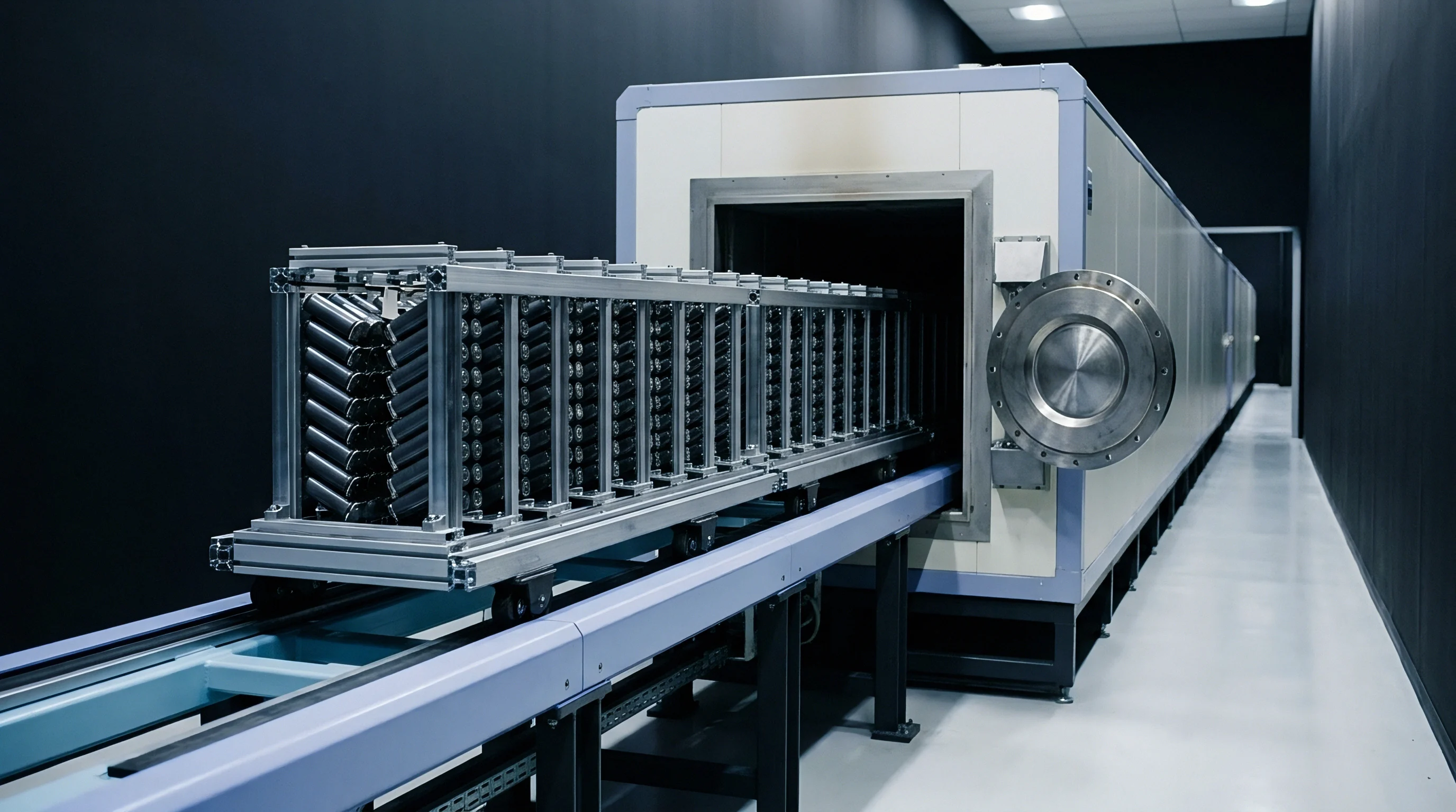
Destructive physical teardowns offer ground truth for mapping plating boundaries. Following low-temperature charging in environmental chambers, cells are transferred directly into an argon glovebox maintained below 0.1 ppm oxygen and moisture for immediate harvesting.
- Chilling the charged cell to minus twenty degrees Celsius locks chemical states prior to transfer through the glovebox antechamber.
- Anode harvesting proceeds with ceramic or plastic tools to eliminate short-circuit risks during case de-crimping.
- Visual inspection documents plating patches, identifying the metallic silver sheen against the golden or grey hues of lithiated graphite.
- Scanning electron microscopy characterizes morphology, resolving mossy textures and dendritic branching along active edges.
- Solid-state NMR or X-ray diffraction resolves the precise molar ratio of metallic to intercalated lithium throughout the harvested sample.
Requiring a mandatory three-hour post-charge rest during qualification testing forces suppliers to demonstrate that cells recover without exhibiting secondary voltage plateaus.
Clause
Procurement contracts formalize acceptable operating windows, auxiliary pre-heating budgets, and lifetime degradation thresholds. Technical datasheets typically compress allowable sub-zero currents to trickle levels, leaving system integrators to reconcile those bounds with customer expectations, parasitic heating loads, and overall pack economics.
Pre Heating Thermal Management Constraints
Active thermal management offsets low-temperature charging restrictions by bringing cells up to temperature before main charging current flows. Architects weigh external resistive pads and liquid loops against high-frequency AC self-heating. Internal AC excitation leverages cell impedance to generate rapid, volumetric heat without creating sharp thermal gradients through the jelly roll.
AC pre-heating draws substantial pulse current, consuming stored pack energy to raise core temperatures from -20°C to +5°C in a matter of minutes. Once the core warms to a safe threshold, normal charging can proceed without triggering plating. System specifications must establish whether parasitic heater consumption is factored into round-trip efficiency guarantees.
Commercial Warranty Boundary Conditions
Suppliers routinely reject warranty claims if BMS logs show charge current exceeding datasheet boundaries under sub-zero conditions. Sourcing teams counter by embedding strict operational clauses into supply contracts so warranties hold under genuine cold-climate deployment.
Solid agreements define charge envelopes across granular temperature intervals, specifying allowable C-rates down to -30°C. Language should govern physical sensor placement across modules ~ banning ambient cabinet readings in favor of worst-case surface probes ~ and define clear fault allocation for cold-charging degradation, using high-precision coulometry and differential capacity metrics to arbitrate disputes.
Binding pre-heating requirements directly to cell supply agreements aligns cold-weather charging expectations with target cycle life while keeping warranty protections intact.