Inter Cell Pressure Distribution Analysis in Dynamic Swelling Pouch Modules
Dynamic swelling in pouch modules demands tuned inter-cell foam compliance and rigid end plates to prevent localized lithium plating and capacity degradation.
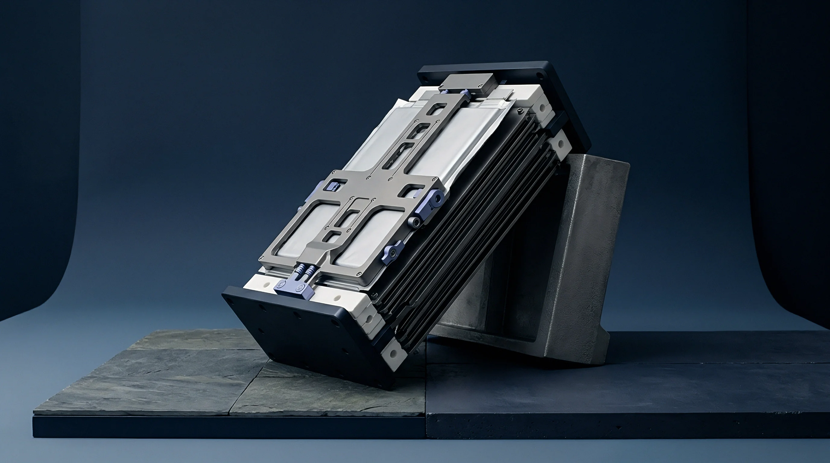

Gradient
Tactile sensor sheets placed between fifty-ampere-hour nickel-manganese-cobalt pouch cells register a baseline contact force of 0.20 megapascals at thirty percent state of charge. When current ramps to 1.5C during fast charging, local readings at the geometric center of the active area climb past 0.85 megapascals while the perimeter margins adjacent to the heat seals linger below 0.12 megapascals. This uneven mechanical profile stems from non-uniform current density distributions, thermal gradients created by tab heat generation, and the crystallographic expansion of the graphite-silicon composite negative electrode during lithiation.
Graphite expands by approximately ten percent along its c-axis when reaching the stage-one LiC6 stoichiometry, whereas silicon particles expand beyond two hundred and eighty percent upon full lithiation. Because current lines naturally converge near the positive and negative current collector tabs, electrochemical reaction rates peak near the top edge of the pouch. Localized state of charge races ahead of the cell average.
The center of the jelly roll experiences both thermal stagnation and mechanical confinement from adjacent cells, causing dynamic localized swelling to outpace the expansion of peripheral regions.
A thirty-cell module held at 0.3 megapascals average pre-load develops internal peak stresses exceeding 1.1 megapascals at full charge under 2C continuous discharge.
Thickness changes compound across cells. In a module comprising twenty to forty serial pouch cells, the total stack expansion produces substantial axial forces against the retaining bulkheads. A rigid retention system converts volumetric strain into mechanical stress.
If the stack cannot expand freely along its axis, the internal pressure field alters the porous structure of the separator and the composite electrode coatings, which in turn influences local ionic conductivity and tortuosity.

Mechanical Response across Electrode Topographies
Slurry coating tolerances generate subtle variations in mass loading between the center of the electrode web and the slotted edges. During slot-die coating on production lines, surface tension and drying dynamics induce a slight crowned profile across the coated strip, typically running two to four microns thicker at the centerline than at the trimmed boundary. Over thirty-two bicell layers inside a single pouch packaging envelope, these microscopic thickness variations accumulate into a macroscopic ridge.
Intercalation expands the graphite lattice. When external clamping platens compress the cell stack, the mechanical load transfers primarily through these elevated zones. The resulting contact interface develops a pronounced saddle or dome geometry.
Local contact areas experience elevated shear stresses at the interface between the aluminum-plastic laminate foil and the outermost separator layer.
| Measurement Zone | Initial Pre-load (MPa) | Peak Charge Stress (MPa) | Discharge Residual (MPa) | Electrode Strain (%) |
|---|---|---|---|---|
| Center Geometric Face | 0.22 | 0.88 | 0.29 | 8.4 |
| Tab Convergence Zone | 0.25 | 0.74 | 0.31 | 7.1 |
| Active Area Edge Boundary | 0.14 | 0.32 | 0.16 | 3.2 |
| Sealing Flange Margin | 0.02 | 0.04 | 0.02 | 0.4 |
Cyclic loading redistributes liquid electrolyte within the porous separators and electrodes. Under intense localized normal loads, electrolyte squeezes out of the highly compressed central core toward unconstrained edge margins and gas collection pockets. This hydraulic displacement leaves the central active materials partially starved during high-rate discharge pulses, raising cell internal impedance and accelerating capacity decay across prolonged field operation.
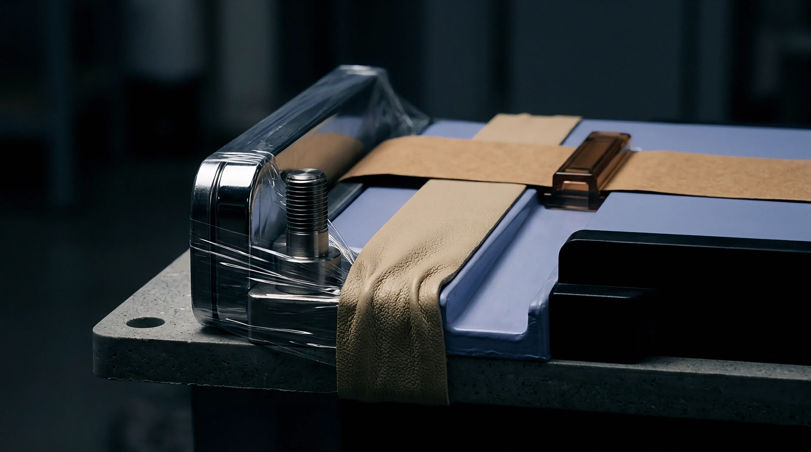
Foam
Elastomeric cushions placed between adjacent pouches absorb cyclic swelling while maintaining sufficient pressure to prevent active material delamination. Cellular polyurethane and closed-cell silicone foams serve as the primary damping media within commercial traction packs. Selection of the foam grade hinges on the stress-strain compression curve, specifically the compression force deflection profile measured under environmental cycling between minus thirty and sixty degrees Celsius.
An ideal inter-cell cushion operates within its plateau region, where substantial dimensional variations induce only modest shifts in normal stress. Open-cell foams collapse early. If the foam enters its densification regime during normal operational swelling, the effective modulus spikes by two orders of magnitude, converting compliant damping into rigid mechanical constraint.
- Uncompressed positioning involves placing die-cut foam sheets with acrylic transfer adhesive onto the dry cell face with three millimeters boundary setback from the seal seam.
- Module pre-compression compresses the cell and foam assembly to a fixed reference length using a servo-driven platen fixture operating at five millimeters per minute.
- Tension banding secures laser-welded stainless steel straps around the stack while the load frame maintains twenty kilonewtons of axial clamping force.
- Load relaxation monitoring measures the force decay over a twenty-minute dwell period to account for initial viscoelastic foam relaxation prior to final weld locking.
Viscoelastic relaxation complicates long-term pressure maintenance. Under sustained compression at fifty degrees Celsius, microcellular polyurethane cushions exhibit steady stress relaxation, dropping forty to sixty percent of their initial holding force within the first five hundred thermal cycles. Silicone foams maintain elasticity across wide temperature swings but exhibit lower tear resistance and higher raw material costs per square meter.
A compressible pad operating past its densification knee transfers destructive hydraulic shock loads directly into the module tie rods.
Thermal conductivity through the cushion represents another interface trade-off. Standard cellular silicone delivers an unassisted thermal conductivity near 0.2 watts per meter-kelvin, which thermally isolates adjacent pouches from each other. Introducing alumina or boron nitride fillers lifts conductivity to 1.2 watts per meter-kelvin while inevitably stiffening the foam matrix, which increases the modulus and reduces allowable strain absorption before reaching densification.
A soft cushion accommodates cyclic breathing without transferring high loads to the module chassis.

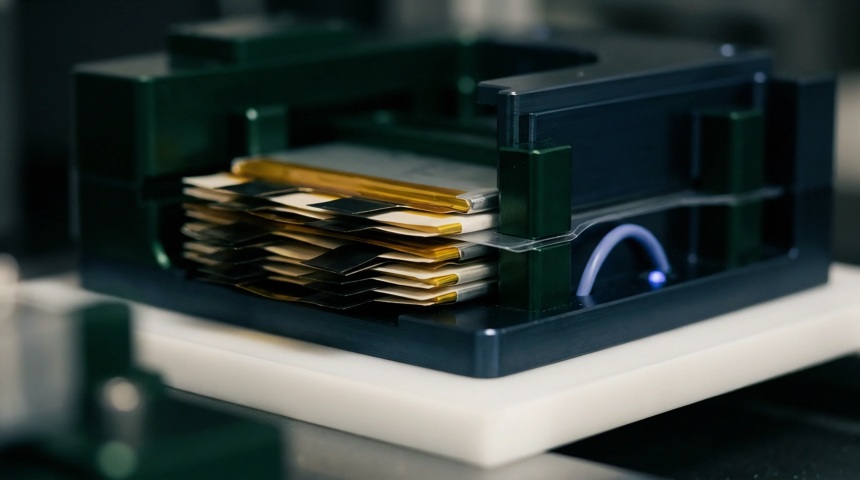
Plating
Lithium deposition on the graphite surface initiates whenever the local negative electrode potential drops below zero volts versus the lithium reference electrode. This electrochemical vulnerability accelerates under non-uniform compressive stress fields. Elevated normal stresses compress the porous polyethylene separator, reducing its physical thickness and squeezing its pore structure.
Ionic conduction pathways become tortuous, driving up the local electrolyte resistance.
In zones subjected to excessive mechanical clamping, separator pore collapse lowers ionic transfer rates through the liquid phase. Concurrently, the overpotential of the negative electrode shifts negative. When fast charging drives high current through these pinched zones, metallic lithium deposits in dendritic or mossy morphologies instead of intercalating into the graphite lattice sheets.

Is Localized Plating Reversible during Rest Periods?
Re-intercalation of metallic lithium into the host graphite structure occurs during extended open-circuit relaxation periods, provided the lithium maintains electrical contact with the electrode matrix. Stripping efficiencies during subsequent discharge cycles rarely reach one hundred percent. Portions of the deposited lithium lose electrical connection due to separator mechanical action and continuous solid electrolyte interphase reactions, forming dead lithium and permanently trapping active inventory.
The boundary where high pressure transitions to low pressure represents the primary nucleation site for dendrites. Overhang zones, where the negative anode extends beyond the positive cathode sheet by one to two millimeters to capture edge flux, become particularly susceptible when pressure non-uniformity tilts current distribution toward the perimeter.
| Applied Stack Stress (MPa) | Separator Thickness (µm) | MacMullin Number | Plating Onset SOC (%) | Plating Severity Area (%) |
|---|---|---|---|---|
| 0.05 | 20.2 | 8.2 | 78 | 4.1 |
| 0.20 | 19.6 | 8.8 | 84 | 1.2 |
| 0.50 | 18.1 | 11.4 | 69 | 9.8 |
| 1.20 | 14.8 | 19.6 | 42 | 28.5 |
Dendrites growing in the high-pressure tab margin zones can pierce compromised separators, generating localized micro-shorts that register as anomalous self-discharge rates. The cell voltage drops over storage periods, and localized temperature elevations accelerate calendar degradation.

Degradation Patterns in High-Mileage Packs
Automotive road testing reveals distinct wear markings on dismantled pouch cells retrieved from warranty returns. Optical microscopy confirms that graphite exfoliates preferentially under high-stress focal points created by module retention bolts. The active layer sheds from the copper current collector foil, creating an isolated island of inactive material surrounded by heavily plated lithium rings.
Industry specifications limiting allowable local pressure variance to fifteen percent across the active area do not apply universally, as cell architectures using composite silicon-graphite blend negative electrodes tolerate twenty-five percent variance if the base temperature remains above thirty degrees Celsius. Sourcing teams mitigate this ambiguity by requiring cell suppliers to map the dynamic pressure threshold across a wide temperature window rather than accepting single-point room-temperature benchmarks.
Standard IEC 62660-1 cycle endurance data collected under unconstrained free-swelling conditions overstates actual module life by twenty to thirty-five percent compared to life under rigid spring-loaded constraints.
Whether non-destructive ultrasonic transmission mapping can reliably distinguish between localized dead lithium deposits and localized gas pocket formation during in-pack service remains unresolved across production testing environments.
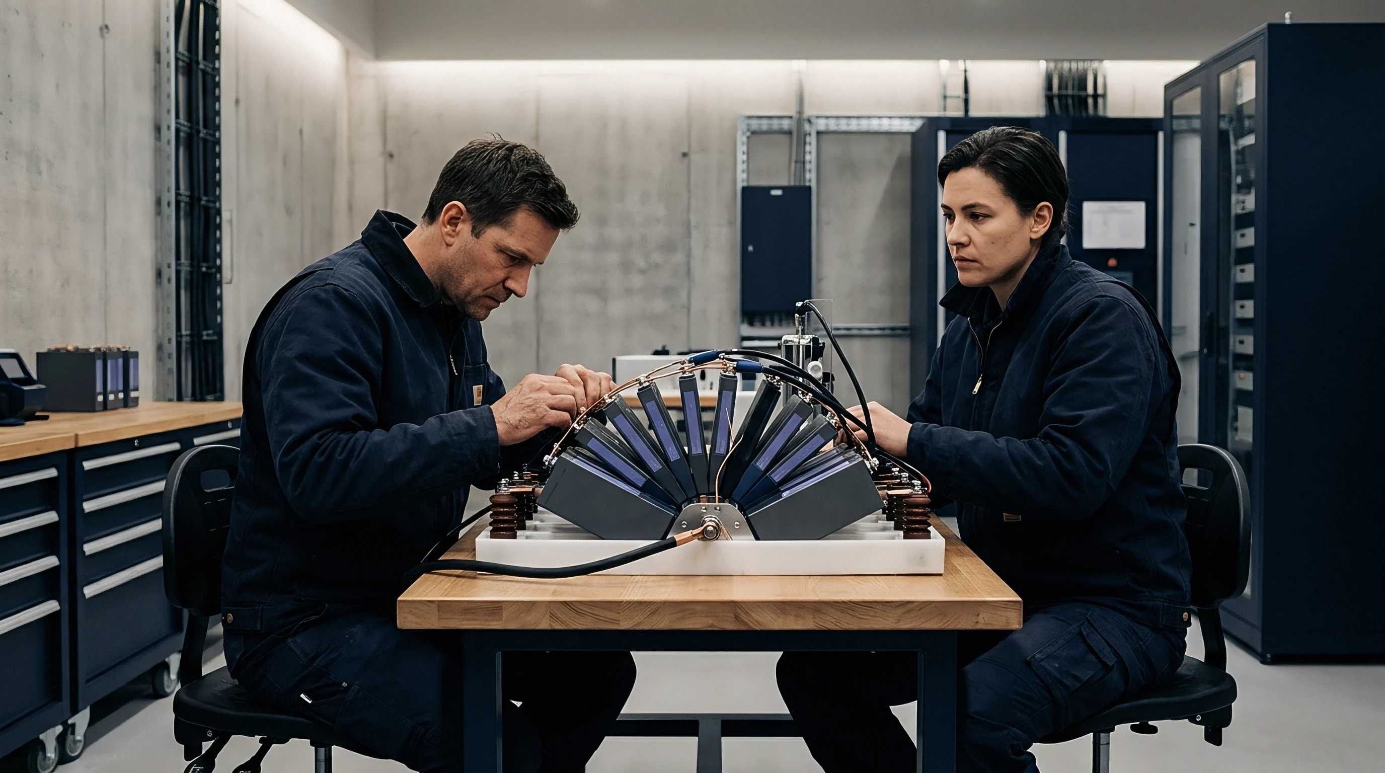
Fixture
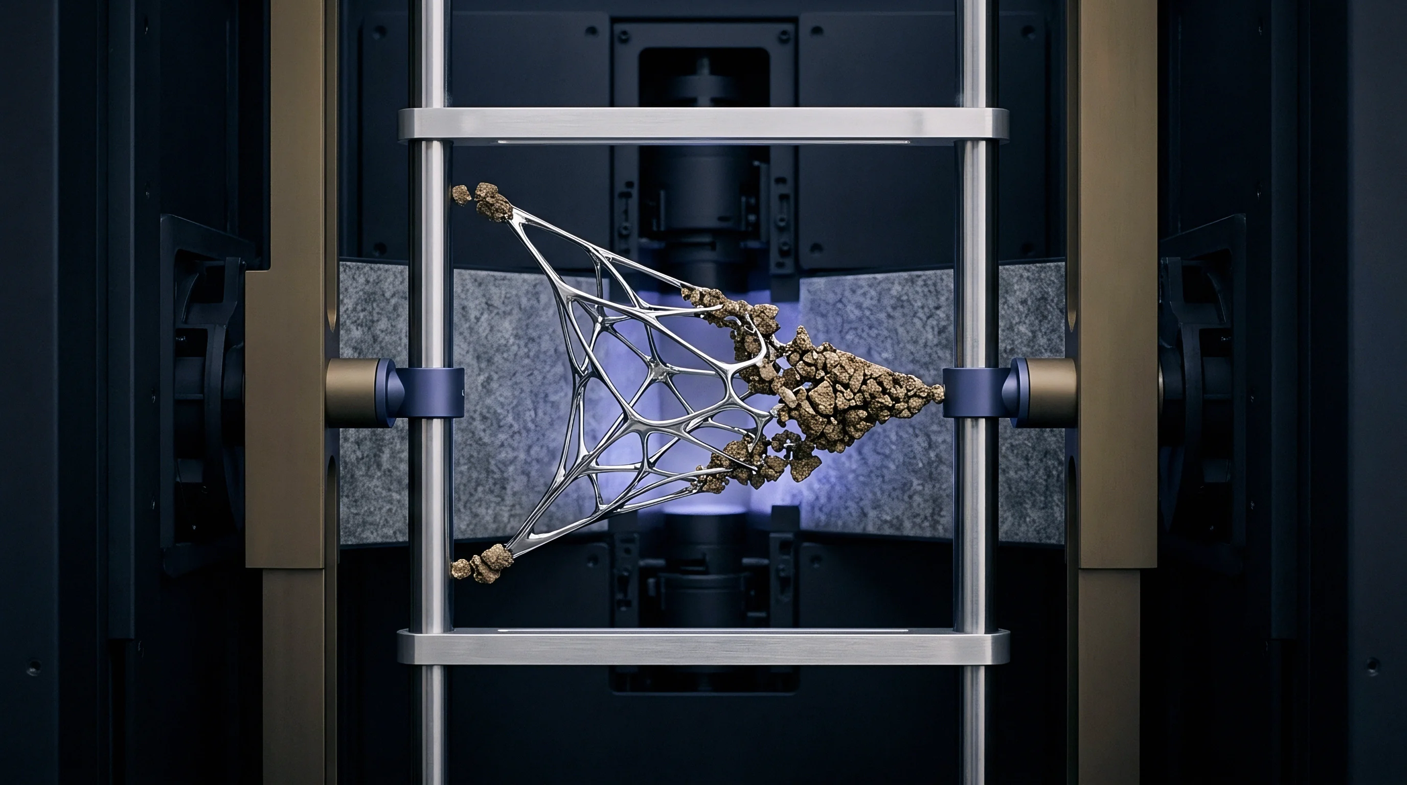
End plates and tension straps define the mechanical boundary conditions of the pouch stack. Structural engineers routinely select cast aluminum alloys such as A380 or extruded 6000-series aluminum to balance mass, stiffness, and tooling expenditure. The stiffness of these end plates governs the pressure distribution across the outermost cells of the module.
Under internal swelling pressures, flat end plates undergo bending deformation, creating a classic convex curvature. The center of the plate deflects outward while corner tie rods or side plates anchor the edges. Consequently, the outermost pouches experience relief of normal compression at their center, while edge zones near the fasteners take concentrated peak reaction forces.
Will End Plate Deflection Exceed Center Limits?
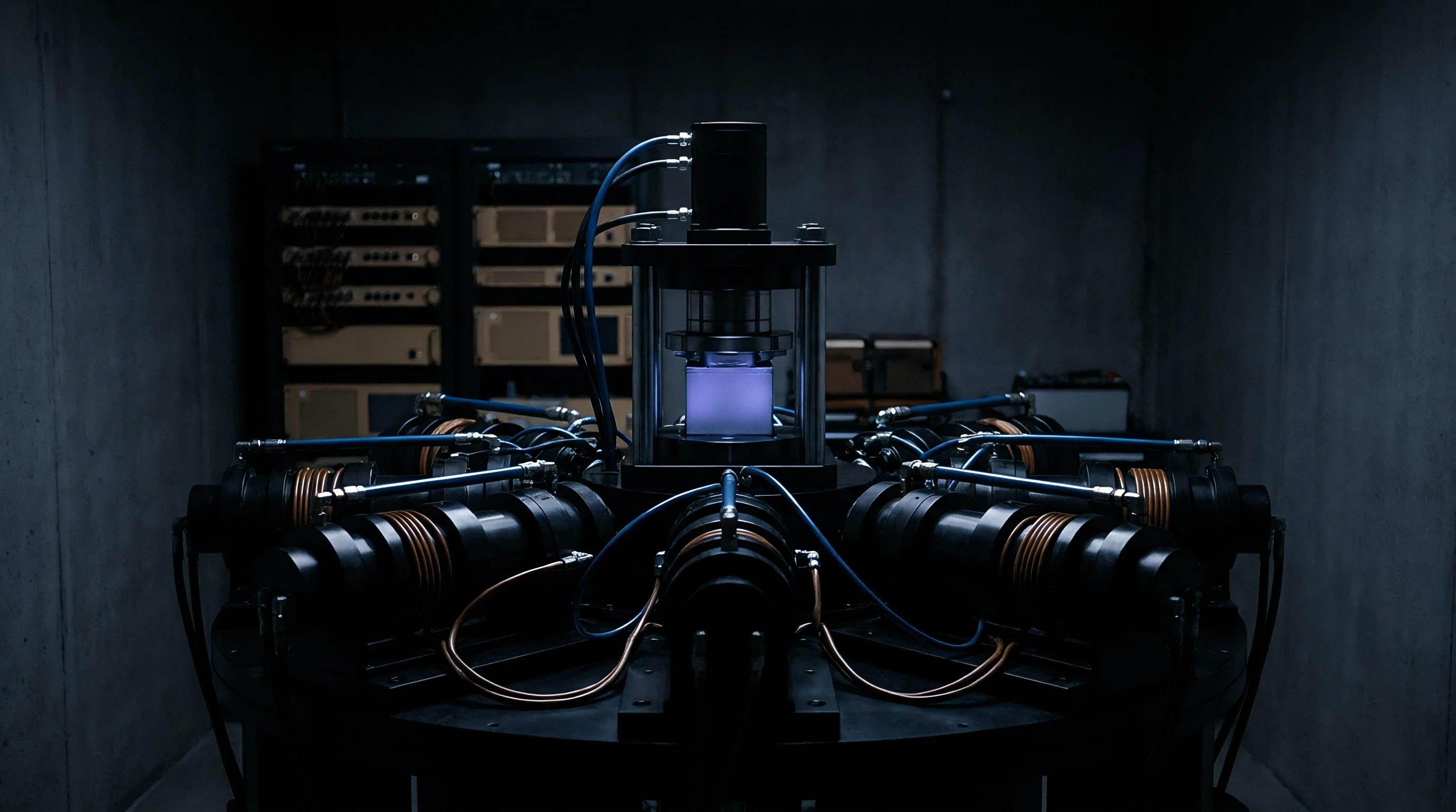
Finite element structural calculations must verify that the deflection across the transverse axis of the end plate remains below 0.35 millimeters under end-of-life swelling conditions. If center displacement exceeds this limit, the center-to-edge pressure ratio drops below 0.4, causing loss of contact pressure at the center of the outer cell while pinching its edges. Structural ribs cast into the external face of the bulkhead stiffen the component without adding excessive wall thickness.
In long modules containing more than twenty pouches, center cells experience peak loads as the structural compliance of intermediate cooling plates modifies axial stress transmission. Aluminum cooling plates equipped with internal micro-channels transmit compressive loads directly through their solid structural lands, creating a high-frequency alternating pattern of localized contact stripes across the pouch face.
- Ribbed bulkhead casting reinforces the end plate against hydraulic deflection modes while preserving packaging clearance for high-voltage wiring harnesses.
- Peripheral tie-rod clamping concentrates tensile reaction loads at the perimeter corners, necessitating thick outer flanges on the structural side members.
- Side strap laser stitching distributes shear retention loads across the module length through spaced autogenous stitch welds along the sheet-metal rails.
- Integrated elastomeric end pads absorb the angular mismatch caused by plate bending, dampening the edge stress concentrations on the first and last cells.
High-voltage line equipment in automotive assembly plants resembles heavy civil hydraulic machinery during the cell pack compression sequence. Multi-axis servo presses drive hydraulic rams against the module end plates, compressing the dry stack to nominal build dimension before automated laser optics weld the side retaining rails.
Inter-cell compression pads are designed to absorb mechanical deflections produced by end plate bending moments throughout standard operational life cycles.
Arbitration
Commercial contracts between cell suppliers, module integrators, and vehicle manufacturers must delineate exact responsibility boundaries for swelling-induced field degradation. A cell manufacturer delivers an unwrapped pouch with a guaranteed nameplate capacity, but that capacity depends directly upon the external mechanical boundary conditions imposed by the module assembly. The warranty interface splits along the line between internal electrochemical swelling and external structural confinement.
An unconstrained cell expands freely in thickness, but its cycle life drops rapidly due to active mass isolation and delamination from the current collectors. Conversely, an over-constrained cell maintains electrical contact but risks localized lithium plating, separator puncture, and pouch seal burst. The module specification defines an envelope of allowable mechanical pre-load and allowable end-of-life swelling force.
| Enclosure Architecture | Tooling Cost (USD) | Compliance Owner | Assembly Cycle (s) | Warranty Seam Location |
|---|---|---|---|---|
| Cast Ribbed End Plate + Straps | 140,000 | Module Integrator | 45 | Strap Weld Quality |
| Extruded Enclosure Box | 85,000 | Pack Fabricator | 70 | Cell Insertion Tolerances |
| Stamped Sheet Metal Clam | 42,000 | Cell Supplier / Tier 1 | 30 | Sheet Rivet Joint Margin |
| Tie-Rod Through-Bolted Rig | 18,000 | Contract Manufacturer | 110 | Nut Torque Drift Over Time |
Production lines running at thirty parts per minute struggle to hold tab alignment within plus or minus 0.5 millimeters across fifty consecutive cells. When cell pouches shift slightly inside the module frame, the active area overhang changes position relative to the inter-cell foam pad, creating local stress discontinuities across the active boundary.
Once stamping dies and casting molds are machined, altering the inter-cell cushion thickness or changing the end plate rib layout requires expensive re-tooling charges and delays the vehicle start of production by several months. Sourcing engineers protect production schedules by demanding dynamic swelling data across five hundred cycles at multiple pre-loads before signing off on the tooling release documentation.
Section 8.2 of the master supply agreement establishes that capacity fade claims become void if average stack pressure exceeds 0.65 megapascals at full charge or drops below 0.08 megapascals at discharge during the initial thirty-six months of service.