Meaning
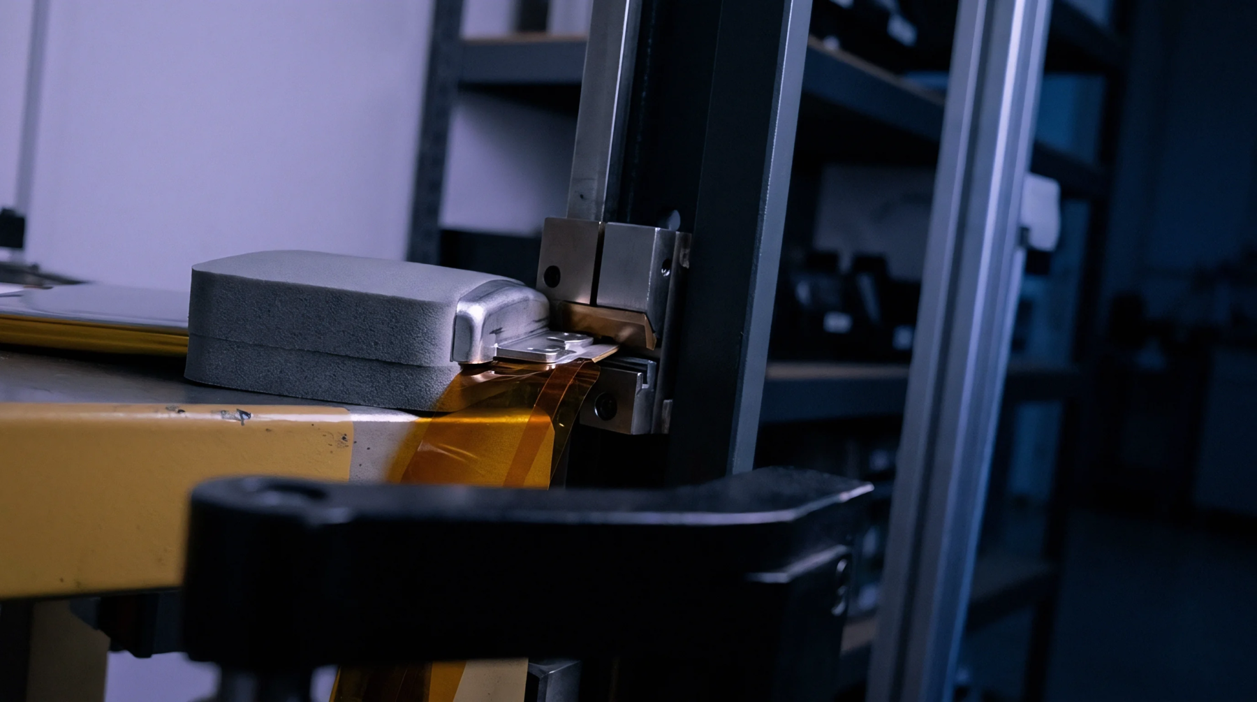
Rigid or flexible metallic conductors designed to join multiple battery cells into a unified high current circuit. These busbar interconnects carry the primary power load from the anode or cathode terminals to the main assembly lugs. They replace traditional wire bundles to reduce the physical volume and increase the electrical efficiency of the pack.
Typical materials include aluminum or copper depending on the weight requirements and the target thermal conductivity. The physical shape helps manage current density while providing enough surface area for cooling air to circulate freely. These components serve as the central highway for electrons moving within the module or across entire battery strings.
Metal Selection
High purity copper remains the standard choice for busbar interconnects when high current capacity must occupy minimal space. When total module weight matters more than volume, aluminum provides a lightweight alternative that requires careful terminal plating to avoid oxidation. This layer prevents corrosion at the point where the metal meets the chemical cell terminal.
Engineers often select plated copper to gain the benefits of low resistance and environmental protection. Each selection moves the total price of the assembly because base metal prices fluctuate on the global market. Thermal expansion coefficients must match the cell housing to prevent mechanical strain during use.
If the expansion rates differ significantly, the joints might crack under heat stress.
Joinery Method
Secure attachment happens through ultrasonic welding or high power laser beams depending on the material thickness. For large busbar interconnects, mechanical bolts with locking washers provide the necessary tension to ensure low resistance contact over time. These bolts require specific torque settings to maintain stability during high vibration transport.
Automated vision systems inspect the quality of the bond between the conductor and the terminal point. If a weld is incomplete, the localized resistance increases and causes heat to build during discharge periods. Such hot spots can lead to localized failures or thermal incidents if left uncorrected.
Correct bonding ensures the entire array contributes equally to the total power output of the device.
Physical Routing
Geometry inside the battery enclosure determines the path these busbar interconnects follow from the front modules to the rear ones. Staggering the paths helps avoid electromagnetic interference with delicate monitoring wires nearby. Flexible sections allow the assembly to survive mechanical shocks without breaking the continuity of the electrical flow.
These bends provide strain relief as the cells naturally expand during the normal charging process. Clear insulation layers protect the metal from accidental contact with the grounded pack frame. Safety depends on maintaining minimum clearance distances between conductors of different polarity.
High voltage ratings determine exactly how much space must separate these flat metal strips within the compact interior of the container.