Busbar Materials and the Corrosion Nobody Budgets
Galvanic corrosion across bare copper-aluminum busbar joints creates escalating thermal interfaces that erode pack life and trigger unbudgeted warranty claims.
Galvanics
When atmospheric moisture reaches a high-voltage battery enclosure, dissimilar conductors in physical contact form an active electrochemical cell. Designers specifying copper and aluminum interconnects routinely size for ampacity and conductivity under static thermal models, ignoring the galvanic potential across structural interfaces. In the presence of ambient ionic contaminants, the potential difference between oxygen-free high-conductivity copper (C11000) and electrical-grade aluminum alloys (such as 1050 or 6061) exceeds 1.50 volts.
That delta drives continuous anodic dissolution of the aluminum through repeated thermal cycles.
A pack does not need to flood for this reaction to proceed. Water vapor enters sealed enclosures through barometric pressure swings, membrane vent breathing, and localized condensation along thermal gradients during fast charging. Inside the housing, moisture absorbs trace volatile organic compounds, sulfur dioxide, and nitrogen oxides from ambient air to form a thin, high-mobility electrolyte film.
Once that film bridges bare aluminum and copper, the aluminum turns sacrificial. Electrons flow to the copper cathode while aluminum atoms at the interface oxidize into Al³⁺ ions. These precipitate with hydroxide species as non-conductive aluminum hydroxide films, narrowing the conduction path and driving up interfacial resistance.
This resistance jump triggers a self-reinforcing thermal cycle. Higher junction resistance increases local Joule heating (I2R losses) during high-current pulses. The heat spike temporarily dries the contact point, but micro-fractures in the brittle oxide layer expose fresh metal as soon as the assembly cools and moisture recondenses.
Over thousands of operating hours, a low-resistance metallic interface turns into an oxidized boundary of brittle intermetallics and porous hydroxide salts. The failure mode rarely presents as a clean open circuit; instead, it develops into a localized thermal runaway hotspot long before isolation monitors register a ground fault.
Electrochemical Potential Voltages in Micro-Environments
Assessing galvanic risk between busbar alloys starts with the electromotive force series. Under standard conditions (unit activity solutions), pure copper has a standard reduction potential of +0.34 volts versus the standard hydrogen electrode, while aluminum sits at -1.66 volts ~ a theoretical thermodynamic potential drop of 2.00 volts. Inside an operating battery enclosure, however, passive surface oxide layers shift these rest potentials.
In practice, the open-circuit potential difference between C11000 copper and 1050 aluminum in neutral aqueous salt conditions settles between 0.70 and 0.90 volts.
Even with oxide passivation, that differential sits far above thresholds established in marine and aerospace engineering. ISO 14713 and MIL-STD-889 require galvanic couples exposed to humid air to maintain an open-circuit potential delta below 0.15 volts to prevent accelerated corrosion. Any differential above 0.50 volts ~ including bare copper against aluminum ~ rapidly degrades the anodic material.
Swapping bare copper for nickel-plated copper pulls the potential difference against aluminum down to 0.15 to 0.25 volts. That drop significantly suppresses the thermodynamic driving force of the corrosion cell, though aggressive halides like chloride ions in condensation can still sustain localized attack.
| Conductor Material Couple | Anodic Material | Cathodic Material | Practical Potential Delta (V) | Corrosion Risk Rating |
|---|---|---|---|---|
| C11000 Copper to 1050 Aluminum | 1050 Aluminum | C11000 Copper | 0.75 – 0.90 | Severe Thermal Degradation |
| Nickel-Plated Cu to 1050 Aluminum | 1050 Aluminum | Nickel Plating | 0.15 – 0.25 | Moderate Ambient Risk |
| Tin-Plated Cu to 1050 Aluminum | 1050 Aluminum | Tin Plating | 0.05 – 0.15 | Low Ambient Risk |
| Silver-Plated Cu to 1050 Aluminum | 1050 Aluminum | Silver Plating | 0.90 – 1.05 | Extreme Localized Pitting |
| C11000 Copper to 304 Stainless Steel | C11000 Copper | 304 Stainless (Passive) | 0.20 – 0.35 | Low to Moderate Risk |
The rate of metal loss tracks the cathode-to-anode surface area ratio. A small aluminum tab fastened to a massive copper busbar forces high anodic current density through a narrow footprint, causing severe localized pitting and rapid thinning. Conversely, landing a small copper lug onto a wide aluminum plate distributes dissolution across a larger area, slowing penetration depth.
Layouts that place small aluminum interconnect tabs against heavy copper distribution plates routinely accelerate thermal joint failures during high-humidity vehicle trials.

Intermetallic Layer Growth and Thermal Runaway Chains
Direct metallurgical bonding like laser welding or friction stir welding brings copper and aluminum into atomic contact, preventing room-temperature aqueous galvanic cells at the joint interface. However, thermal cycling during service and the elevated heat of the weld process itself trigger solid-state diffusion, forming brittle intermetallics like CuAl2, Cu9Al4, and Cu3Al. These intermetallic phases have electrical resistivities up to five times higher than either parent metal, paired with high hardness and virtually no ductility.
Once thermal aging pushes these layers beyond micrometer-scale thicknesses, mechanical stresses fracture the intermetallic zone, allowing moisture and airborne electrolytes into the resulting sub-surface voids.
When moisture enters an intermetallic weld zone, crevice corrosion accelerates galvanic breakdown. In tight geometries where oxygen replenishment is restricted, the small amount of dissolved oxygen inside the crevice is quickly depleted by initial oxidation. The resulting differential aeration cell causes metal ions within the crevice to hydrolyze, driving local pH levels below 3.0.
This acidic pocket dissolves the internal aluminum oxide film and attacks the weld root, even while the exterior bead remains visually clean during standard end-of-line inspections.
An interfacial contact resistance increase exceeding 0.45 mΩ across a laser-welded copper-aluminum junction indicates sub-surface intermetallic layer corrosion under damp heat conditions.
Testing on a high-voltage commercial transit pack at 85°C and 85 percent relative humidity showed electrical resistance across a bare copper-aluminum busbar bridge rising by 310 percent over 1,200 hours, while the temperature rise under a 350-ampere load climbed from 14°C above ambient to 82°C above ambient. The localized heat accelerates solid-state diffusion, thickening the intermetallic layer and compounding joint resistance. Left unchecked, this feedback loop initiates thermal runaway directly at the busbar junction rather than from an internal cell short-circuit.
Preventing this failure mode requires true environmental isolation or intermediate plating barriers. Enclosure perimeter seals cannot completely block moisture transport through structural polymers over a 5 to 10-year vehicle design life. Rubber grommets, gaskets, and plastic carrier frames slowly transmit ambient humidity into the housing cavity.
Once cold weather pulls the aluminum chassis below the dew point, condensation settles directly onto the busbars. Without barrier coatings or suitable plating, galvanic degradation begins during the pack’s first cool-down cycle.
Procurement specs need to define corrosion resistance through environmental stress testing rather than generic ingress protection ratings. While Paragraph 4.2 of ISO 2081 specifies electroplated zinc and nickel coatings for ferrous substrates, battery pack supply contracts require dedicated addenda for non-ferrous busbars exposed to condensation. Purchase orders that simply request commercial brightness or clean surfaces leave the buyer exposed, transferring millions in warranty costs to the pack integrator when unprotected interfaces corrode in service.

Plating
Surface coatings on raw copper and aluminum busbars remain the primary barrier against galvanic corrosion and contact resistance creep. Electroplating, electroless deposition, and mechanical cladding alter conductor surface chemistry, replacing active dissimilar metal pairs with stable, matched layers. Specifying insufficient plating thickness, poor barrier chemistries, or flawed deposition parameters creates latent reliability risks.
Sourcing groups often opt for thin-flash plating to reduce piece costs without accounting for how micro-porosity in thin deposits concentrates galvanic action into deep pitting sites.
Plating methods differ substantially in density, pore structure, and ductility. Bright electroplated nickel provides high hardness and resists fretting wear, but its high internal tensile stress causes micro-cracks when busbars are formed or stamped after plating. Matte nickel deposits with lower internal stress, offering better ductility during post-plating bending at the expense of slight surface hardness.
Electroless nickel immersion gold (ENIG) creates uniform coverage across complex geometries, maintaining required tolerances in tapped holes and stamped contact dimples where line-of-sight electroplating methods suffer from low current density.
Tin plating offers an economical, conductive surface that flows plastically under bolt torque, wiping away native oxides and yielding low initial contact resistance. But tin melts at 232°C and diffuses rapidly into raw copper at elevated pack operating temperatures. Without an intermediate barrier layer, copper migrates into the tin to form brittle Cu6Sn5 and Cu3Sn intermetallics.
This consumes the free tin layer, exposes the base metal to oxidation, and triggers tin whisker growth. These conductive filaments grow under compressive stress and can bridge creepage distances across adjacent BMS signal traces or high-voltage conductors.
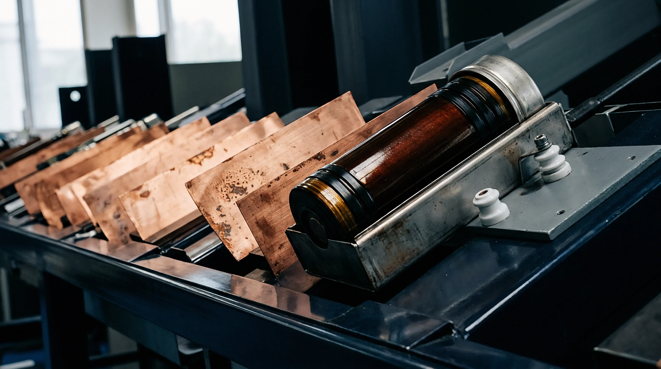
Barrier Layer Mechanics and Thickness Metrics
Stopping copper-tin interdiffusion requires a dense intermediate barrier layer. Sulfamate nickel electrodeposition is the standard choice, providing low internal stress and good ductility. A 3.0 to 5.0 micrometer sulfamate nickel barrier prevents copper migration into top-layer tin or gold coatings at temperatures up to 125°C. Reducing this barrier under-plate below 2.0 micrometers allows copper atoms to diffuse along grain boundaries within 500 thermal cycles, causing surface tarnishing, contact resistance spikes, and accelerated corrosion in damp environments.
Thickness verification must cover the entire busbar profile. X-ray fluorescence (XRF) spectrometry provides accurate, non-destructive measurements on flat coupons, but checking only the center of a flat run misses the thinning that occurs along stamped edges, inside bend radii, and around hole chamfers. Plating current density naturally concentrates at external corners and drops inside internal radii.
A busbar specified for a nominal 8.0 micrometers of nickel at the center may have under 1.5 micrometers around internal bends, leaving high-stress zones unprotected.
| Plating Stack Architecture | Barrier Layer Thickness | Top Layer Thickness | Pore Density (pores/cm²) | Thermal Limit (°C) | Cost Impact Factor |
|---|---|---|---|---|---|
| Matte Tin over Sulfamate Nickel | 3.0 – 5.0 µm Ni | 5.0 – 8.0 µm Sn | < 2.0 | 150 | 1.00 (Baseline) |
| Electroless Nickel / Gold (ENIG) | 4.0 – 6.0 µm Ni-P | 0.05 – 0.10 µm Au | < 0.5 | 200 | 2.45 |
| Silver Flash over Bright Nickel | 2.0 – 4.0 µm Ni | 1.5 – 3.0 µm Ag | < 1.5 | 180 | 1.80 |
| Direct Flash Tin on Raw Copper | None | 1.0 – 2.5 µm Sn | > 25.0 | 85 | 0.65 |
| Bimetallic Clad (Cu-Al Roll Bonded) | None (Solid Interface) | 0.5 – 1.0 mm Cu Clad | 0.0 | 220 | 3.10 |
Microscopic porosity in plated coatings is difficult to detect during standard incoming visual inspections. Pinhole voids form when hydrogen gas bubbles adhere to the substrate during electrodeposition, leaving direct paths to the base metal. When a porous tin-over-copper busbar meets condensation, galvanic corrosion initiates inside these channels.
The volume expansion of trapped corrosion products then blisters and lifts the plating layer, exposing raw copper to ambient oxidation.

Manufacturing Defect Mechanisms in Plated Conductor Assemblies
Manufacturing order directly dictates the finished quality of plated conductors. Plating flat sheet before stamping lowers chemical processing costs, but shearing and forming cut straight through the coating stack. Stamping dies leave bare copper or aluminum exposed along the entire cut perimeter, while bending stretches the outer tension face, cracking brittle nickel underlayers and exposing the base metal beneath.
Plating fully formed busbars resolves edge exposure and bend cracking, but introduces chemical entrapment risks. Intricate busbar geometries ~ such as folded terminal tabs, laminated leaf stacks, or riveted voltage sense leads ~ draw pickling acids and plating chemistries into narrow crevices via capillary action. If wash sequences do not thoroughly rinse these seams, residual plating salts remain trapped inside.
Under thermal cycling, these residual chemistries attack internal surfaces, destroying joint conductivity before outside humidity ever enters the housing.
Plating defects at busbar bend radii expose base metal long before atmospheric exposure manifests as visible galvanic corrosion.
Cross-sectional microscopy of tin-plated copper busbars pulled from a fleet trial following BMS isolation faults showed that the parts had been stamped and formed after electroplating. This left raw copper exposed along every cut edge and opened micro-cracks through the nickel barrier along each 90-degree bend. Condensation inside the enclosure turned these micro-cracks into galvanic pitting sites, generating heavy copper carbonate deposits that bridged the creepage distance to the grounded chassis frame.
Preventing these defects requires strict process specifications and incoming quality audits. Quality plans should require post-forming plating followed by environmental and chemical testing. The following failure modes must be screened during first-article approval and lot sampling:
- Edge plating depletion occurs when electroplating current densities drop inside internal cutouts and stamped edges, leaving thin coating protection that fails prematurely under salt fog exposure.
- Substrate outgassing blisters arise when organic rolling lubricants trapped inside raw copper or aluminum micro-voids expand during high-temperature reflow or ultrasonic welding processes, lifting the plating stack.
- Intermetallic embrittlement zones form when thick copper-tin intermetallic layers grow through thin tin topcoats, eliminating the soft contact surface needed to maintain low contact resistance under mechanical clamping pressure.
- Passivation chemical residues remain trapped within multi-layer laminated flex busbar assemblies, driving galvanic corrosion across internal nickel-copper contact foils under operating electrical bias.
- Stress-induced whisker growth develops on bright tin coatings subjected to non-uniform mechanical clamping pressure, creating conductive tin filaments that bridge isolation barriers across adjacent low-voltage BMS signal traces.
When corrosion appears early, debates over whether minor staining and micro-cracks meet commercial tolerances or whether edge thinning is unavoidable during stamping often stall resolution. Conceding on cut-edge coverage shifts commercial liability directly to the pack integrator, as ambient moisture readily attacks unplated edges in service.

Joint
Module-to-busbar joints provide both mechanical structure and electrical continuity across the high-voltage circuit. Selecting a joint architecture involves trade-offs between contact resistance, thermal compliance, assembly cycle times, and mechanical relaxation over time. Bolted connections, laser welds, ultrasonic wedge bonds, and flow-drill screws each handle environmental exposure and torque decay differently.
If an interface is designed without accounting for differential thermal expansion and fretting micro-motion, contact resistance will climb under operational duty cycles.
Bolted joints rely on continuous mechanical clamping force to shear through native oxide films (such as Al2O3 and Cu2O) and deform microscopic surface asperities into direct metal-to-metal contact. However, aluminum undergoes significant mechanical creep and stress relaxation under sustained bolt preload, especially above 60°C. As the aluminum yields and moves away from high-stress clamping zones, bolt preload decays, interface contact pressure drops, and moisture enters the widening micro-gaps.
Differential thermal expansion accelerates this preload loss. Aluminum has a coefficient of thermal expansion (CTE) around 23 ppm/K, compared to 12 ppm/K for steel fasteners and 16.5 ppm/K for copper busbars. When the pack warms during high-rate charging, the aluminum busbar expands faster than the securing steel bolt, pushing compressive stress beyond the aluminum’s yield limit.
When the connection cools, the yielded aluminum leaves a permanent loss of clamping force. This thermal ratchet mechanism progressively degrades joint pressure and raises contact resistance on every charge-discharge cycle.
Laser Welding Dynamics and Dissimilar Metal Metallurgy
Laser welding avoids the mechanical relaxation seen in bolted joints by fusing adjacent conductor faces into a continuous solid interface. Joining copper to aluminum with fiber lasers requires careful tuning of beam geometry, power density, and feed rate to stabilize the keyhole. Because copper reflects infrared light efficiently at room temperature, it requires a high initial power spike to establish the keyhole, followed by immediate power modulation to avoid blowing through thin aluminum cell terminals.
The central metallurgical objective is limiting the formation of brittle intermetallic phases in the weld pool.
High-power continuous wave or pulsed 1070 nm fiber lasers can produce reliable lap welds by shooting through an upper copper layer into an aluminum substrate below. Keeping melt penetration into the lower aluminum tab under 0.20 millimeters minimizes the growth of brittle CuAl2 intermetallics. Deeper penetration pulls excessive aluminum into the melt, yielding a brittle root structure prone to micro-cracking.
These micro-cracks draw in moisture and electrolyte vapors through capillary action, accelerating sub-surface galvanic corrosion that can fracture the weld nugget under road vibration.
| Joint Architecture Type | Initial Preload / Weld Energy | Initial Contact Resistance | Resistance Drift (1,000 Cycles) | Dominant Failure Mode |
|---|---|---|---|---|
| Standard M6 Steel Bolt / Flat Washers | 9.5 Nm Torque | 0.08 mΩ | + 280 percent | Aluminum Creep & Torque Loss |
| M6 Bolt with Belleville Washer Stack | 9.5 Nm Torque | 0.09 mΩ | + 15 percent | Minor Surface Oxidation |
| Laser Lap Weld (Cu to Al) | 1.2 kW / 45 mm/s | 0.02 mΩ | + 85 percent | Intermetallic Root Cracking |
| Ultrasonic Wedge Bond (Al Wire) | 65 W / 400 ms | 0.04 mΩ | + 40 percent | Fretting Corrosion at Heel |
| Flow Drill Screw (Direct Drive) | 6.0 Nm Drive Torque | 0.06 mΩ | + 120 percent | Thread Creep and Oxidation |

How Does Fretting Wear Accelerate Interfacial Failure?
Fretting wear is driven by low-amplitude, cyclic relative motion across mating conductor faces. In vehicle packs, frame flex, road input, and thermal expansion create continuous micro-slip ~ typically 1 to 100 micrometers ~ across unbonded busbar joints. This relative motion shears the metallic contact points established during torque-down, exposing fresh base metal to oxygen within the pack.
The freshly exposed metal oxidizes immediately, producing hard, resistive oxide particles. Ongoing vibration grinds these particles into an abrasive debris bed trapped inside the contact footprint. This fretting corrosion separates the mating surfaces, concentrating current through fewer surviving contact asperities.
Interfacial resistance climbs, driving up local temperatures until insulation chars or arcing occurs across the interface.
Suppressing fretting wear requires either locking the joint mechanically to eliminate relative slip or using dedicated contact greases to seal the joint interface from air. Synthetic fluoroether- or polyalphaolefin-based greases lower friction, hold wear debris in suspension away from contact points, and provide a hydrophobic barrier against moisture. However, greases that bleed oil, harden, or oxidize at high operating temperatures form insulating barriers that degrade joint conductivity faster than a dry interface.
Validating busbar joints requires sequential stress testing to prove mechanical, electrical, and environmental performance before tooling release. First-article joint validation follows this qualification sequence:
- Initial baseline four-terminal Kelvin resistance measurements are recorded across every joint, logging values at room temperature with a high-precision micro-ohmmeter under low-current test conditions.
- The busbar assembly undergoes thermal shock testing according to IEC 60068-2-14, completing 500 cycles between minus 40°C and plus 105°C with a dwell time of 30 minutes at each extreme.
- Sinusoidal and random vibration testing is applied along three orthogonal axes per UN 38.3 requirements, subjecting the assembly to simultaneous thermal cycling to simulate vehicle chassis stress.
- The assembly is transferred directly to a damp heat constant state chamber running at 85°C and 85 percent relative humidity for 1,000 continuous hours per IEC 60068-2-78.
- Interfacial contact resistance is re-measured across all test points every 250 hours during damp heat exposure, logging any joint exhibiting a resistance spike greater than 15 percent above baseline.
- Post-test destructive cross-sectional analysis and energy-dispersive X-ray spectroscopy are performed on selected joint samples to map oxide layer growth, intermetallic diffusion depths, and localized pitting corrosion.
IEC 61238-1 Class A compliance forces qualification testing under 1000 thermal cycles without exceeding a 10 percent junction resistance drift.
Adding Belleville conical spring washers provides an effective mechanical solution to thermal ratchet torque loss in bolted joints. Conical washers store high elastic strain energy, acting as stiff mechanical springs that absorb differential thermal expansion without forcing the aluminum past its yield point. As the joint cools, the Belleville washer recovers, maintaining steady clamping force and preserving gas-tight micro-junctions across thermal cycles.
In any bolted joint design, the usable elastic spring travel must exceed the maximum differential thermal expansion of the conductor stack across the entire operating temperature range.

Ledger
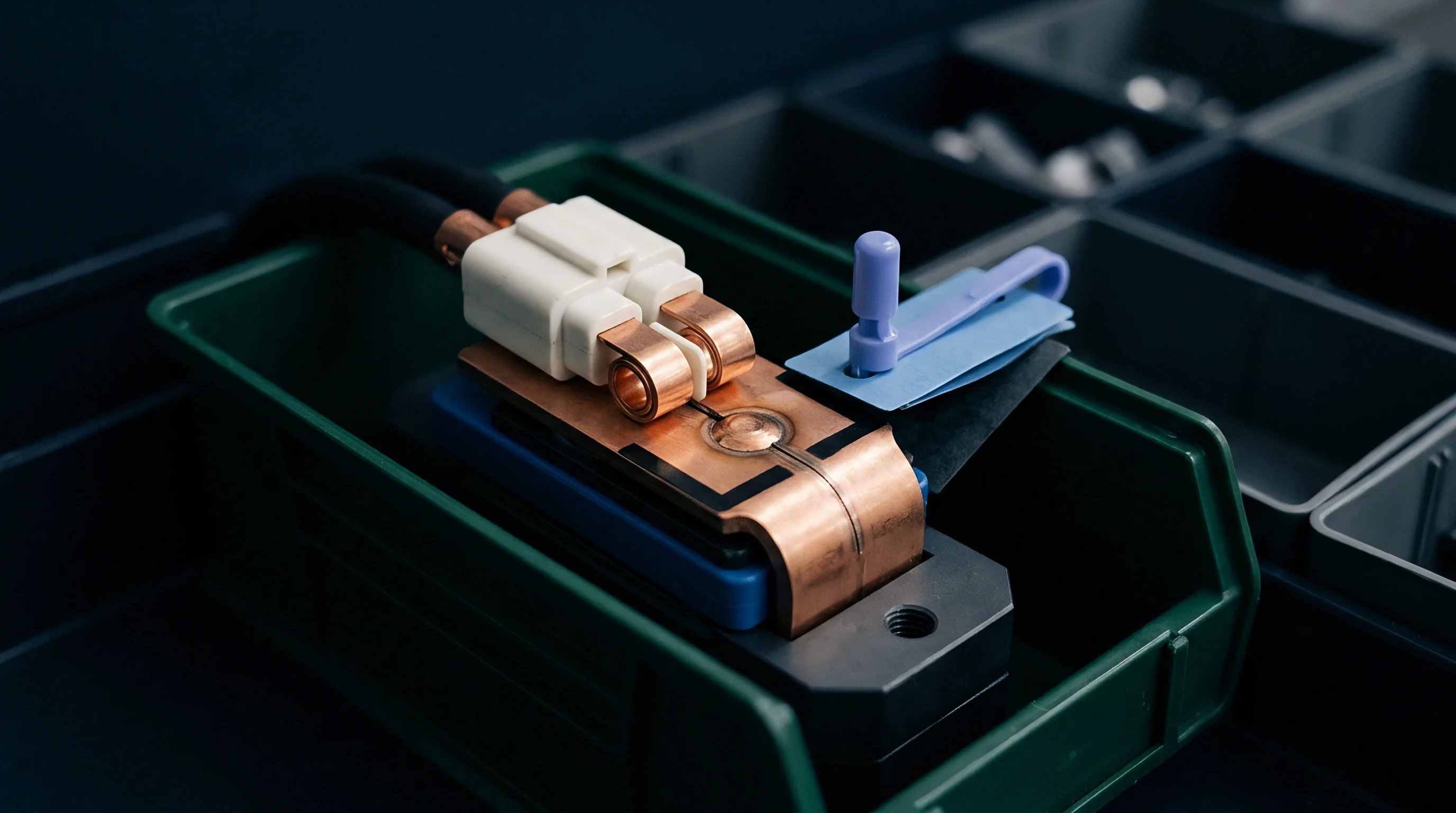
Cost models for battery engineering often isolate initial bill-of-materials (BOM) metal costs while ignoring long-term warranty exposure from joint corrosion. Specifying raw C11000 copper and 1050 aluminum without protective plating or compliant hardware saves cents per pack upfront. But those minor savings introduce failure mechanisms that tend to surface two to four years into vehicle service, leading to pack replacements, field recalls, and warranty reserve adjustments that dwarf the initial component savings.
Calculating the true landed cost of a busbar requires evaluating the complete supply chain: London Metal Exchange (LME) raw metal pricing, non-recurring engineering (NRE) tooling amortization, plating fees, stamping scrap rates, and quality inspection overhead. Raw copper costs roughly three to four times more per kilogram than aluminum, pushing integrators toward aluminum-heavy designs. But making aluminum reliable requires extra processing ~ such as nickel plating, specialized laser welding, or Belleville washer stacks ~ which narrows the final module-level cost delta.
Stamping scrap adds a direct, often unbudgeted cost to production. Blanking complex busbar geometries from flat sheet typically yields material utilization rates between 45 and 60 percent. When coils are plated prior to stamping, all skeleton scrap carries the full cost of the plating chemistry, sending expensive nickel, tin, or silver directly to the recycler at a loss.
Stamping parts first and barrel- or rack-plating afterward captures scrap value as bare metal, cutting overall plating chemical spend at high production volumes.

Warranty Reserve Arithmetic and Field Recall Exposures
Setting warranty reserves for busbar interconnects requires modeling corrosion kinetics against field exposure over time. Interfacial corrosion failures do not follow early infant mortality trends. Instead, they fit Weibull distributions with wear-out shape parameters (β) between 2.5 and 3.8: failure rates remain negligible during the initial warranty window, then climb sharply as moisture penetrates the pack housing in later years.
Consider an integrator building 20,000 commercial delivery vehicle packs annually, with 48 module-to-module busbar joints per pack. Using bare aluminum-to-copper bolted joints saves about $18.50 per pack in upfront plating and hardware compared to a nickel-plated joint with Belleville washers. If moisture triggers interfacial corrosion in just 1.5 percent of deployed packs per year after year three, the economics shift decisively against the unplated design.
Replacing an EV battery pack in the field runs roughly $8,500 across logistics, labor, pack tear-down, and replacement hardware. In a 20,000-unit fleet, a 1.5 percent annual failure rate means 300 replacements a year, or $2,550,000 in direct warranty claims. Amortized across the full 20,000-unit build, that adds $127.50 in warranty cost per pack ~ erasing the $18.50 upfront savings nearly seven times over.
Sourcing decisions based solely on purchase order piece price routinely miss this liability.
| Busbar Protection Strategy | Upfront Component Cost / Pack | Tooling NRE Amortization | Projected 8-Yr Failure Rate | Realized Warranty Exposure / Pack | Net Total Landed Cost / Pack |
|---|---|---|---|---|---|
| Bare Cu-Al Bolted (Flat Steel Washers) | $42.00 | $12,000 | 4.20 percent | $357.00 | $399.00 |
| Nickel-Plated Cu to Al (Belleville Spring) | $60.50 | $18,000 | 0.15 percent | $12.75 | $73.25 |
| ENIG Plated Cu to Al (Laser Welded) | $78.00 | $65,000 | 0.02 percent | $1.70 | $79.70 |
| Bimetallic Clad Interface (Laser Welded) | $88.50 | $45,000 | 0.01 percent | $0.85 | $89.35 |
Regulatory mandates under the European Battery Regulation (EU 2023/1542) and standards like UL 1973 and IEC 62619 raise the cost of unmanaged material changes. Under battery passport rules, integrators must document material traceability, purity, and recycled content for all high-voltage conductor parts. Switching a busbar vendor, changing plating thickness, or dropping a barrier layer requires updated compliance filings and invalidates existing safety test documentation.
Re-certifying a pack design to UN 38.3 transport standards and UL 1973 stationary storage requirements costs between $45,000 and $110,000 in test lab fees alone, plus the cost of prototype packs consumed in destructive testing. Sourcing teams that change busbar vendors mid-program to capture piece-part savings often trigger recertifications that wipe out the anticipated margin gains before the first batch ships.
Supplier contracts must explicitly define financial liability for field failures caused by corrosion defects. RFQ packages should define enforceable quality limits covering manufacturing processes, plating thickness verification, and environmental stress testing. The checklist below outlines key quality verification gates required prior to issuing production tooling purchase orders:
- XRF layer validation certificates are required for every electroplating production lot, verifying minimum barrier layer and topcoat coverage across critical bend radii and contact faces.
- Salt spray qualification reports per ASTM B117 must confirm zero base metal corrosion or blistering following 500 hours of continuous exposure for all plated busbar assemblies.
- Chemical bath audit logs from plating vendors must prove continuous monitoring of bath pH, organic brightener concentrations, and metal ion purity levels to eliminate porous plating batches.
- Joint torque retention testing documentation must demonstrate that bolted conductor stacks retain a minimum of 85 percent of initial bolt preload after completing 1,000 thermal shock cycles.
- Bimetallic weld cross-sections must be audited on laser welding lines every shift, measuring intermetallic layer thickness growth to confirm values remain strictly below 2.0 micrometers.
Nickel plating thickness specs on engineering drawings regularly fail to account for micro-cracking across formed terminal tabs.
An audit of a tier-one supplier following field isolation faults in stationary storage units revealed an unapproved shift from post-stamping nickel plating to pre-plated strip stock to shave 14 percent off piece costs. The change left every stamped busbar edge bare, allowing atmospheric sulfur and humidity to build copper sulfide creep corrosion across the gap between the busbar and the grounded container enclosure.
Supply agreements must assign full indemnity to the vendor when unauthorized process deviations bypass drawing notes and trigger field claims. Enforcing that liability requires clear, toleranced plating, forming, and joining specifications on engineering drawings that hold up under technical arbitration.
What long-term electrochemical degradation mechanisms remain hidden inside solid-state bimetallic interfaces when battery packs operate past their nominal ten-year design life under high-voltage direct current bias?