Contractual Warranty Risk Allocation and Regulatory Traceability Compliance for High Voltage Interconnects
Allocating interconnect warranty risk relies on strict micro-ohm baseline tracking, 1000V creepage isolation, and serial batch traceability.


Busbar
High-voltage battery packs rely on low-resistance joints that survive thermal cycling, mechanical shock, and continuous vibration over thousands of operating hours. In heavy vehicles or stationary grid installations running between 600V DC and 1500V DC, busbars and interconnects sustain continuous currents above 400 amperes, with fast-charging or emergency discharge peaks reaching 1200 amperes. At that scale, micro-ohm shifts in joint resistance generate localized hot spots that degrade polymer insulation, damage adjacent cells, and risk open-circuit faults or thermal runaway.
Conductor selection generally comes down to pure oxygen-free copper (C10200), electrical tough pitch copper (C11000), or high-conductivity aluminum alloys like 1050 and 6061-T6. Copper delivers roughly 58.0 MS/m in electrical conductivity against aluminum’s 35.5 MS/m, yet aluminum cuts structural mass by more than 50 percent for an equivalent ampacity. That weight savings introduces galvanic risk: direct copper-aluminum interfaces corrode rapidly in humid environments unless isolated with transition materials.
Designers insert bimetallic friction-welded transitions, laser-clad strips, or nickel barrier plating to separate the 2.0-volt galvanic couple between the two metals.

Metallurgical Joinery and Interface Physics
Attaching conductor strips to cell terminals requires tight thermal limits to minimize interface resistance without transferring destructive heat into the cell core. Terminal headers ~ ranging from cylindrical 21700/4680 caps to prismatic M6/M8 threaded posts ~ tolerate minimal heat input during pack assembly. High-volume manufacturing lines lean primarily on ultrasonic wedge bonding and laser wobble welding.
Each process introduces distinct mechanical properties, metallurgical failure modes, and inspection burdens that carry direct contractual liability.
Laser welding fuses overlapping conductors within a narrow melt pool. When joining copper to aluminum, thermal delivery must be strictly controlled to suppress the growth of brittle intermetallics like Cu9Al4 and CuAl2 along the boundary. These phases exhibit microhardness values exceeding 600 HV, leaving the joint vulnerable to shear fracture.
Wobble optics oscillate the beam pattern to agitate the melt pool, distributing heat over a broader area to keep the brittle intermetallic boundary layer under 3 microns thick.
Ultrasonic wedge bonding avoids the liquid phase entirely. Transverse acoustic vibrations between 20 kHz and 60 kHz scrub surface oxides from the mating faces under high clamping pressure, driving solid-state atomic diffusion well below the metals’ melting points. Because no melt pool forms, intermetallic phases do not develop, yielding a ductile bond.
Under acoustic stress conditions, bond foot dimensions must remain within a 5 percent tolerance to reach specified shear values.
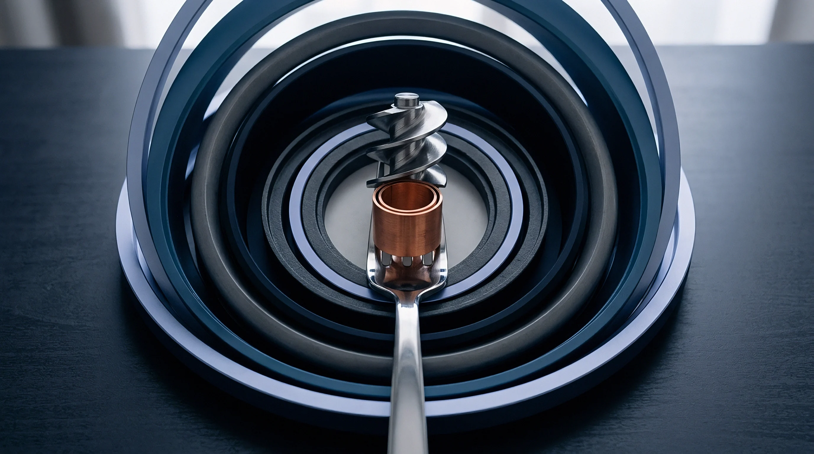
Laser Wobble Welding versus Ultrasonic Wedge Bonding
The choice between laser welding and ultrasonic bonding dictates tooling design, inline inspection architectures, and line yield. Laser welding requires tight joint fit-up: interfacial gaps exceeding 10 percent of the upper sheet thickness result in blow-through, voiding, or incomplete penetration. Fixturing must restrict part clearance to under 0.05 millimeters across the full weld seam, backed by machine vision and inline laser triangulation sensors checking profile height immediately after the beam passes.
Ultrasonic bonding accommodates slight variations in joint fit-up, but demands exceptional surface cleanliness. Residual stamping oils, organic films, or thick oxide layers dampen acoustic energy transfer, creating unbonded cold joints and elevated contact resistance. High-throughput lines frequently place atmospheric plasma cleaning stations immediately ahead of the bonders.
Tool degradation presents an ongoing process variable: as wedge grooving erodes, acoustic coupling decays and bond strength drops. Production systems track energy delivery, tool deformation depth, and process dwell time per bond to catch drift.
| Joining Methodology | Interface Resistance (micro-ohms) | Shear Strength (MPa) | Thermal Limit (Degrees Celsius) | Intermetallic Thickness Limit |
|---|---|---|---|---|
| Laser Wobble Weld (Cu to Cu) | 12 ± 2 | 180 to 220 | 150 continuous | Not Applicable |
| Laser Wobble Weld (Cu to Al) | 28 ± 5 | 110 to 140 | 120 continuous | Less than 3.0 microns |
| Ultrasonic Wedge Bond (Al Wire) | 45 ± 6 | 70 to 90 | 105 continuous | Zero phase growth |
| Ultrasonic Ribbon Bond (Cu Ribbon) | 22 ± 3 | 140 to 160 | 130 continuous | Zero phase growth |
| Mechanical Bolted Joint (Ag-Plated) | 35 ± 4 | 240 to 280 | 105 continuous | Not Applicable |
Bolted joints remain the standard interface at pack service disconnects, fuse mounts, and master output terminals. These assemblies use silver-plated copper contact pads clamped under high preload with Belleville disc springs. Silver plating prevents base-copper oxidation and stabilizes interface resistance across operating life.
Fastener torque requires narrow process windows: over-torquing permanently flattens Belleville springs past their yield point so they can no longer compensate for thermal relaxation, while under-torquing promotes micro-fretting wear under vibration, rapidly driving up electrical resistance.
Ampacity Sizing and Thermal Creep Dynamics
Conductor cross-sections balance allowable ohmic loss against thermal rejection limits. Continuous ampacity calculations apply modified Neher-McGrath equations or 3D finite-element thermal simulations, incorporating skin and proximity losses from high-frequency inverter ripple produced by silicon carbide power stages. Conductor sizing is commonly engineered to limit bulk temperature rise to 30 degrees Celsius over pack ambient at continuous rated current.
Exceeding this thermal threshold accelerates mechanical stress relaxation in clamped copper and aluminum joints.
Thermal creep in aluminum represents a primary failure mechanism in mechanically clamped joints. Under sustained contact pressure and thermal cycling up to 85 degrees Celsius, aluminum yields and flows away from high-stress contact zones. This relaxation reduces contact preload, increasing interface resistance and triggering localized Joule heating that accelerates further creep.
Incorporating 17-7 PH stainless steel Belleville washers maintains compliant clamping force across thousands of thermal cycles, mitigating metal displacement.
Joint resistance measured above 45 micro-ohms after 1000 thermal cycles between minus 40 degrees Celsius and 85 degrees Celsius indicates severe intermetallic phase growth.
Busbar routing must decouple dynamic vehicle chassis flex from fragile cell terminals. Enclosure torsional deflection on uneven roads can turn rigid busbar spans into structural struts, transferring chassis loads directly into terminal seals. Designers insert flexible expansion loops or laminated copper shunts across module interfaces to absorb displacement.
Laminated shunts stack multiple 0.1-millimeter copper foils, diffusion-bonded at the terminal ends while remaining loose across the flexible bridge, preserving low bending stiffness alongside full ampacity.
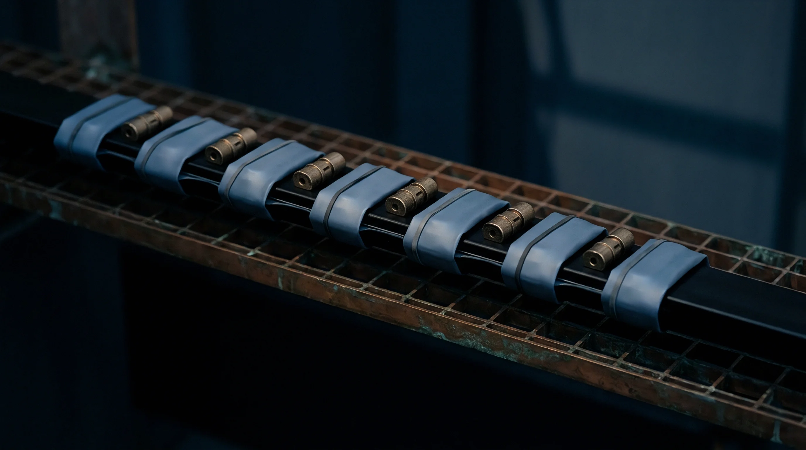
Creepage and Clearance under High Voltage DC Distances
High-voltage packs operating above 600V DC require rigorous physical separation to prevent surface tracking, flashover, and dielectric breakdown. Governed by standards such as IEC 60664-1, creepage defines the shortest distance along solid insulating surfaces between conductors, whereas clearance is the direct line-of-sight distance through air. Required dimensions depend on system working voltage, overvoltage category, anticipated pollution degree, and the Comparative Tracking Index (CTI) of the insulating substrate.
Moisture ingress, condensation cycles, and volatile outgassing inside sealed enclosures create an aggressive internal environment. Enclosure interiors are generally rated for Pollution Degree 2 or 3 unless equipped with active desiccant breathers and certified IP67/IP6K9K sealing. For an 800V DC nominal system under Pollution Degree 2 with Material Group I insulators (CTI above 600), baseline clearance requires at least 3.2 millimeters, with a minimum creepage path of 8.0 millimeters.
Volumetric constraints in dense pack architectures often mandate molded dielectric barriers or conformal overmolding to artificially extend surface tracking distances.
End-of-line Hi-Pot testing validates dielectric isolation before pack shipment by applying high-voltage potential between the live busbar network and the grounded chassis enclosure. Standard production protocols apply twice the maximum working voltage plus 1000 volts for a 60-second dwell. For an 800V architecture with a 900V peak charge ceiling, this requires applying 2800V DC while verifying leakage current remains below 1.0 milliampere.
Insulation breakdown, partial discharge, or micro-arcing during the dwell interval triggers immediate pack rejection for clearance violation or dielectric contamination.
When first-article testing reveals high joint resistance, disputes typically center on whether storage oxidation or wedge-bonder process control caused the shift.
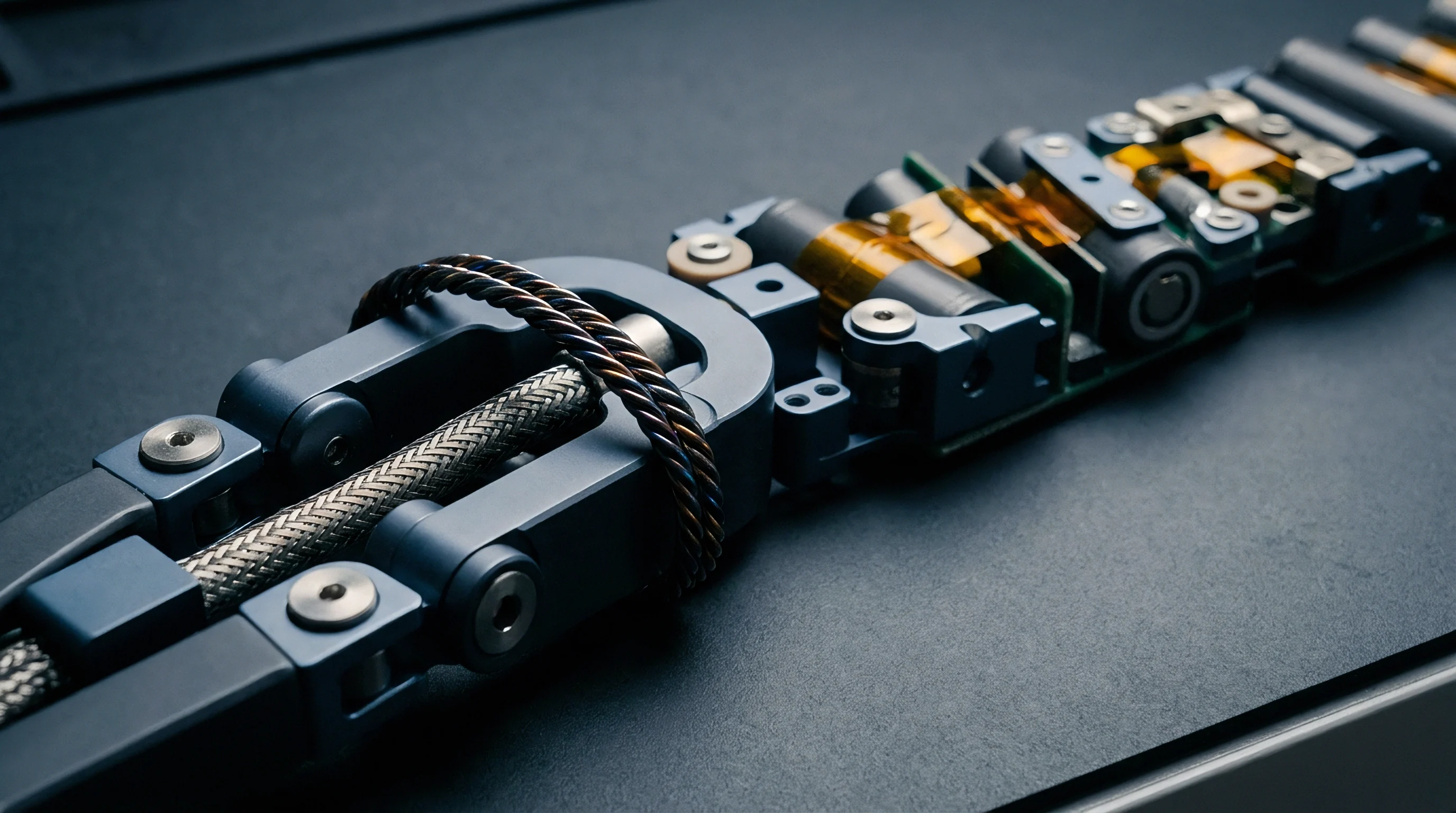
Dossier
Regulatory frameworks across Europe and North America require battery manufacturers to compile unalterable traceability records for every sub-assembly in a high-voltage architecture. Mandates such as EU Battery Regulation (EU 2023/1542) enforce unbroken data trails from mineral extraction through end-of-life recycling, encompassing structural busbars, contactors, fuses, and joinery. A missing mill test report or unrecorded weld parameter invalidates conformity documentation for the entire pack, exposing manufacturers to border holds and non-compliance fines.
Traceability originates on the tier-one supplier floor. Incoming raw coils, dielectric sleeves, and fastener batches receive unique lot numbers mapped directly to metallurgical mill test reports. For copper stock, logged parameters include electrical conductivity (% IACS), material purity (such as 99.95 percent minimum for oxygen-free grades), and grain size distribution.
This chain links chemical and physical properties directly to stamped busbar batches before parts reach the module assembly line.

Digital Passport Specifications and Regulatory Frameworks
The EU Battery Passport replaces static paper dossiers with machine-readable digital ledgers. Industrial and EV traction packs over 2 kWh deployed in the European market must link to a centralized record accessible via an external QR code. High-voltage busbar assemblies contribute foundational data to this entry, including exact alloy mass breakdowns, recycled metal fractions, and cradle-to-gate embedded carbon figures.
Data ingestion relies on standardized exchange schemas. Dossier metadata incorporates bill-of-materials declarations tracking cobalt, nickel, lithium, aluminum, and copper mass down to individual gram increments. Because busbar networks represent a substantial fraction of total copper and aluminum content in a pack, unverified material origin blocks customs clearance at EU borders.
System access and ledger sign-offs require ISO/IEC 27001-compliant controls to prevent retrospective modification of line test logs.
The list below details compliance gaps that commonly turn up during third-party audits of high-voltage assembly lines:
- Material Certificate Discrepancies surface when heat numbers on mill test reports don’t match the batch codes stamped on incoming crates.
- Missing Inline Weld Logs occur when laser welding cells drop network connectivity and fail to attach energy and beam-displacement data to part serial numbers.
- Uncalibrated Inspection Fixtures happen when optical gap sensors run past their calibration dates without signed engineering waivers.
- Incomplete Sub-tier Dossiers occur when plating sub-contractors omit silver thickness measurements from lot documentation.
- Unlinked Rework Records occur when manual touch-up welds skip optical scanner logging stations during offline pack repair.
Audit readiness requires live integration between Manufacturing Execution Systems (MES) and regulatory data repositories. Querying an individual pack serial number must retrieve the full birth history within seconds: cell-to-busbar weld signatures, four-wire micro-ohm resistance logs, tooling IDs, and environmental temperature and relative humidity captured during enclosure sealing.

Material Provenance and Serialization Integrity
Direct part marking forms the basis of physical component serialization. High-voltage busbars receive direct 355 nm ultraviolet laser marks, which etch high-density Data Matrix codes onto copper or aluminum without creating heat-affected zones or mechanical stress. These markings must survive downstream electroplating, heat-shrink sleeve application, and thermal shock testing while sustaining a 100 percent first-pass optical read rate on production scanners.
Indexing serial numbers directly to mill heat charges allows engineering teams to trace material anomalies back to specific production runs. If a copper coil exhibits out-of-spec yield strength that induces micro-cracking across 90-degree form bends, serialized records enable containment of the affected parts across raw inventory, work-in-progress queues, and installed packs, preventing broad vehicle recalls for localized material defects.
| Data Field Category | Specific Parameter Logged | Regulatory Requirement Mapping | Retention Duration (Years) |
|---|---|---|---|
| Raw Material Provenance | Heat number, alloy grade, purity, IACS conductivity | EU Battery Reg Art 7Primitive Material Origin | 15 |
| Manufacturing Execution | Laser power, wobble amplitude, clamp pressure, speed | ISO 26262 / IATF 16949 Quality Records | 10 |
| Inline Quality Testing | Micro-ohm resistance, shear test sampling, optical depth | IEC 62619 / UN 38.3 Module Compliance | 10 |
| Insulation Verification | Hi-Pot voltage, leakage current, dwell time, humidity | UL 1973 / ECE R100 Electrical Safety | 12 |
| Field Lifecycle Data | Peak current events, max joint temperature, cycle count | EU Battery Passport Dynamic Data Structure | End of Life |
Sub-tier compliance enforcement relies on routine incoming validation. Raw stock suppliers must submit accredited ISO 17025 chemical analysis reports with each shipment. Receiving inspection verifies critical dimensions on coordinate measuring machines, measures conductivity via eddy-current testing, and cross-sections coupons to check for subsurface inclusions or porosity.
These verification records are logged to the master traceability system prior to releasing stock to the stamping lines.
Quality Retention and Audit Dossier Architecture
Traceability archives must remain readable across extensive compliance horizons. Supply agreements typically require data availability for 10 to 15 years after end-of-production. To insulate archives from vendor software obsolescence over multi-decade cycles, platforms store structural datasets in open XML or JSON schemas alongside standardized PDF/A documents.
Compliance under EU Battery Regulation Article 77 mandates digital battery passport accessibility for ten years following commercial market placement.
Physical audits systematically cross-examine digital records against actual pack hardware. Compliance auditors sample production packs, dismantle modules, and scan the Data Matrix markings etched onto internal conductors. The decoded serial numbers query the production database; discrepancies between recorded weld resistance values and physical joint layouts, or missing mill test certificates, can trigger suspension of vehicle homologation and freeze finished goods shipments.
Contracts specify that if a supplier fails to upload complete material certification data within 48 hours of lot delivery, the buyer can reject the shipment at the supplier’s expense.
Seam
Warranty disputes over high-voltage interconnects typically center on whether joint failure originated from assembly defects or field over-current abuse. When a busbar connection fails thermally under load, physical evidence is often obscured by melted insulation and damaged cell headers. Resolving liability requires unambiguous contractual definitions of operating limits alongside agreed forensic protocols for root-cause teardowns.
Liability partitions along mechanical interfaces. The cell manufacturer warrants terminal post integrity up to the weld interface. The busbar supplier guarantees alloy purity, stamping tolerances, dielectric sleeves, and surface plating.
The pack integrator controls welding energy, clamping preload, fixture alignment, and inline resistance screening. The OEM manages pack thermal systems, fuse clearing curves, and enclosure sealing integrity. Determining fault when a failure occurs requires systematic metallurgical and electrical analysis.

Operational Boundaries and Failure Attribution
Establishing operating boundaries begins with baseline measurement before hardware leaves the plant. Automated four-wire Kelvin probes measure electrical resistance across every joint pair during end-of-line testing. Initial joint resistance typically measures between 10 and 30 micro-ohms, depending on interface geometry and metallurgy.
These baseline values are written to BMS non-volatile memory and synced to cloud production databases.
Field operational logs provide essential context during forensic teardowns. The BMS monitors continuous pack current, inter-module voltage drops, and thermistor channels located along primary busbar tracks. When a joint overheats, analysis of historical operational data determines root cause: excessive temperature rise occurring under rated current loads indicates manufacturing flaws such as incomplete weld fusion or interfacial oxidation, whereas sustained current exceedances point to control faults or mismatched fuse protection.
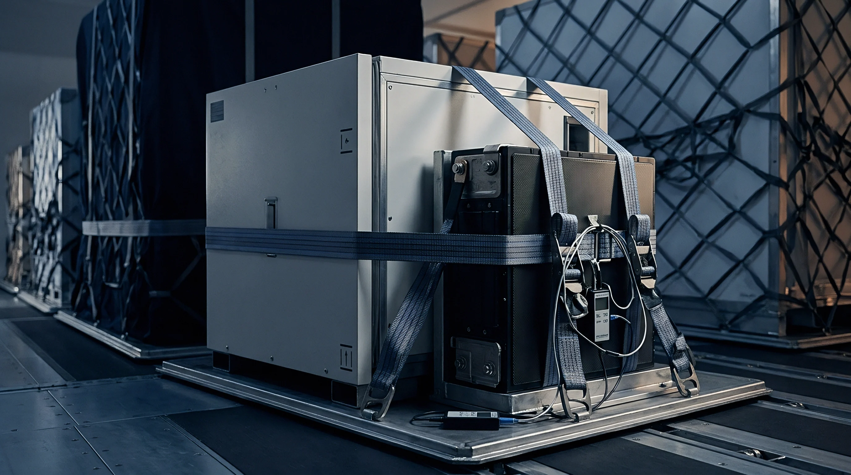
What Governs Fault Attribution at the Interconnect Boundary?
Isolating the root cause at a damaged joint requires systematic tear-down methods. When joint resistance climbs above baseline, engineers run a step-by-step diagnostic protocol designed to evaluate degradation without destroying microstructural evidence.
The procedure below outlines the standard analysis sequence for joint post-mortems:
- Measure overall inter-module resistance with a four-terminal micro-ohmmeter before disturbing the assembly mechanically.
- Run X-ray micro-tomography to check internal weld zones for voids, cracks, or intermetallic layer thickness.
- Perform ultrasonic acoustic microscopy to map delamination across bonded ribbon interfaces or thermal material layers.
- Cut out the damaged joint using a cold diamond saw to preserve local metallic grain structures.
- Mount and polish the cross-section for optical and scanning electron microscopy.
- Run Energy-Dispersive X-ray Spectroscopy (EDS) across the joint line to map elemental diffusion, oxidation, and intermetallic makeup.
- Map microhardness across the heat-affected zone to check for thermal degradation and grain coarsening.
Microstructural analysis differentiates root-cause failure mechanisms with high fidelity. High-cycle mechanical fatigue originates at notch radii and propagates through the conductor cross-section, displaying transgranular beach marks and striations under scanning electron microscopy. Pure thermal over-temperature generates distinct grain coarsening, recrystallization, and intermetallic precipitation.
Galvanic degradation presents localized corrosion products containing chlorine, sulfur, or fluorine concentrated along grain boundaries.

Thermal Cycling versus Vibration-Induced Degradation Mechanics
Thermal cycling and dynamic vibration produce very different stress states inside joint interfaces. Because vehicles subject interconnects to thermal expansion and mechanical loads at the same time, separating the two determines whether a fix requires different alloys or modified mounting hardware.
Thermal stress originates from mismatched coefficients of thermal expansion (CTE). Copper exhibits a CTE of approximately 16.5 x 10^-6 /K, aluminum reaches 23.1 x 10^-6 /K, and FR4 carriers range between 14 and 17 x 10^-6 /K. Cycling between minus 40 and 85 degrees Celsius induces cyclic shear strains across rigid weld interfaces. Over extended thermal cycles, this differential expansion drives low-cycle fatigue, micro-void coalescence, and eventual bond separation.
Mechanical vibration induces high-cycle, low-amplitude fatigue across conductor spans. Pack qualification standards like UN 38.3, IEC 62619, and ISO 16750-3 subject hardware to random vibration profiles spanning 10 Hz to 2000 Hz, with acceleration levels exceeding 3.1 G RMS. When input harmonics align with the natural frequency of an unsupported busbar, resonant displacement amplifies local strain, rapidly propagating fatigue cracks through work-hardened zones until complete mechanical and electrical separation occurs.
| Stress Vector | Accelerated Test Condition | Dominant Degradation Mechanism | Failure Criterion | Governing Standard |
|---|---|---|---|---|
| Thermal Shock | -40°C to +105°C, 15 min dwell, 1000 cycles | CTE mismatch shear stress, intermetallic fatigue | ΔR greater than 20% over baseline | IEC 60068-2-14 |
| Random Vibration | 10-2000 Hz, 5.0 G RMS, 32 hours per axis | High-cycle mechanical fatigue cracking | Mechanical fracture / Open circuit | ISO 16750-3 |
| Humid Heat Cycling | 85°C / 85% RH, continuous 1000 hours | Galvanic corrosion, silver migration | Insulation R less than 100 MΩ | IEC 60068-2-78 |
| Power Cycling | 150% rated current, 5 min ON / 5 min OFF | Joule heating stress relaxation, creep | Joint temp rise greater than 45°C | UL 2580 |
| Salt Mist Corrosion | 5% NaCl solution fog, 35°C, 48 hours | Atmospheric pitting, oxidation layer growth | ΔR greater than 15% over baseline | IEC 60068-2-11 |
The list below pairs environmental stress factors with specific joint failure modes:
- Thermal Expansion Differential creates cyclic shear stress along copper-to-aluminum welds during rapid charging.
- Resonant Structural Vibration causes high-cycle mechanical fatigue at unsupported flexible shunt transitions under road vibration.
- Atmospheric Moisture Condensation triggers galvanic corrosion across unplated bimetallic interfaces under voltage bias.
- Stress Relaxation Creep reduces contact force in bolted terminal connections under long-term thermal exposure.
- Dielectric Tracking Clearance Breakdown leads to high-voltage arcing across contaminated insulation in high humidity.
When joint resistance doubles while insulation resistance remains nominal, mechanical fatigue outpaces thermal degradation in the field failure stack.
Weibull modeling helps quantify failure distributions over time. Plotting field failures yields the shape parameter (beta) and characteristic life (eta). A beta below 1.0 indicates infant mortality from assembly issues like low weld energy or contamination.
A beta around 1.0 points to random failures caused by outside environmental events, while a beta above 3.0 indicates end-of-life wear-out driven by fatigue limits.
The integrator absorbed a 42,000 dollar testing charge after discovering that an uncalibrated micro-ohmmeter had misreported baseline joint resistance across three consecutive prototype validation builds.

Invoice
Contractual liability terms determine how warranty costs, field replacement campaigns, and teardown labor are apportioned when interconnects fail in service. While busbars and joinery typically represent under 4 percent of total pack bill-of-materials cost, a single defective joint can destroy a complete battery system worth tens of thousands of dollars. Standard supplier clauses capping liability at component replacement value shift virtually all financial exposure onto the pack integrator during a recall.
Managing commercial exposure requires aligning indemnification terms with real-world failure consequences. Standard vendor terms often restrict total liability to 100 percent of the purchase price of the delivered part lot. When a two-dollar busbar causes a thermal failure that destroys a forty-thousand-dollar commercial battery pack, that limitation leaves the integrator absorbing 99.9 percent of the financial loss.
Effective supply agreements establish tiered liability caps reflecting failure severity, explicitly incorporating labor, hazardous transport, battery disposal, and forensic teardown costs.

Commercial Risk Allocation and Warranty Capping
Risk allocation relies on contractual defect targets defined in parts per million (PPM). Automotive programs typically mandate incoming component quality under 1 PPM and field interconnect failure rates under 0.1 PPM across the warranty lifespan (such as 8 years or 150,000 kilometers). Exceeding these contractual PPM ceilings automatically triggers enhanced indemnification clauses, shifting supplier liability from piece-part replacement to full campaign cost recovery.
Indemnification clauses categorize claimable costs into explicit buckets: replacement hardware, pack disassembly and rebuild labor at agreed workshop rates, certified hazardous transport, and downtime damages. When root-cause investigation attributes field failures to supplier manufacturing escapes or latent material flaws, the vendor bears campaign expenses up to a negotiated ceiling, typically pegged to annual program purchase volume or required product liability insurance minimums.

Non-Recurring Engineering Amortization and Tooling Ownership
Tooling and Non-Recurring Engineering (NRE) provisions dictate supply chain security and dispute leverage. Fabricating custom busbars requires dedicated progressive stamping dies, bending fixtures, and automated optical inspection nests. Clear legal ownership of these physical assets establishes who controls manufacturing continuity if a supplier fails to meet quality standards.
Agreements should explicitly state that all custom dies, stamping tooling, and automated fixtures funded by the buyer remain the buyer’s exclusive property. While amortizing tooling into piece-part pricing preserves upfront capital, it introduces financial exposure: if a 100,000-unit program cancels at 20,000 units, the supplier will demand the unamortized tooling balance. Contracts require defined settlement schedules for remaining capital tied to actual volume run, while preserving the buyer’s unconditional right to repossess tooling upon payment.
Tooling maintenance covenants require explicit cycle thresholds. Suppliers perform routine die sharpening, punch maintenance, and pin replacement up to an agreed stroke count (such as 500,000 cycles). Beyond that baseline, tool refurbishment or replacement costs transfer to the buyer or trigger secondary amortization terms.
Auditing press stroke counters annually prevents worn tooling from producing edge burrs or dimensional drift on stamped busbar conductors.

Latent Defect Remedies and Commercial Dispute Settlement
Latent defects represent the most severe financial exposure in battery pack manufacturing. These flaws escape end-of-line factory screening and emerge only after sustained operational stress ~ such as sub-surface micro-cracks in stamped aluminum radius bends, sub-micron plating porosity that oxidizes after two years of humidity exposure, or micro-voids concealed inside laser weld seams.
Statutory commercial codes generally restrict defect notification windows to one or two years from delivery, whereas latent busbar flaws often surface much later in product life. Buyers routinely negotiate extended discovery clauses to override these statutory limitations. Under these provisions, when a systematic defect affects a production lot (often defined as exceeding 0.5 percent failure with identical root cause), the notification clock resets, preserving buyer claims for batch containment, lot replacement, and field remedies regardless of component age.
Supplier liability caps expressed as a percentage of annual contract purchase value fail to protect integrators against the full systemic cost of a field recall.
Supply contracts should establish binding technical arbitration protocols before disagreements escalate to formal litigation. When catastrophic field failures occur, engineering teams frequently dispute failure causation. Naming an independent, ISO 17025 accredited testing laboratory to execute post-mortem diagnostics provides a definitive escalation path.
Terms should specify that both parties accept the laboratory’s findings as final, with testing and forensic costs assessed against the non-prevailing party.
Warranty disputes over joint resistance resolve much faster when commercial agreements tie claim payouts directly to four-point micro-ohm measurements recorded at incoming inspection.