Electrochemical Corrosion Kinetics across Dissimilar Conductor Interfaces
Electrochemical corrosion kinetics across dissimilar conductor interfaces accelerate through moisture condensation, demanding perimeter sealing and barrier plating.
Couple
Direct contact between copper and aluminum in a moist environment triggers galvanic corrosion driven by the thermodynamic potential gap between the two metals. Standard reduction potentials place pure copper at +0.34 V versus the standard hydrogen electrode and pure aluminum at -1.66 V. This 2.00 V open-circuit potential forces electron flow from the aluminum anode to the copper cathode whenever an electrolyte film bridges them. In lithium-ion battery modules, this interface occurs where nickel-plated copper busbars mate with aluminum cell terminals or where laser welds join copper collector tabs to external aluminum interconnects.
Joint degradation increases pack resistance long before capacity loss shows up on telemetry, as aluminum oxidizes into insulating aluminum hydroxide.
Mixed potential theory sets the corrosion rate at the intersection of the anodic and cathodic polarization curves. In dry, neutral environments, pure aluminum forms a passive Al2O3 oxide film that keeps exchange current density below 10 nA/cm2. When ionic contaminants such as chloride anions or fluorinated electrolyte breakdown products penetrate this layer, passivity breaks down and anodic aluminum dissolution follows Butler-Volmer kinetics:
i_a = i_0 exp(alpha_a z F eta / (R T))
Here i_0 is the exchange current density, alpha_a the anodic transfer coefficient, z the valence of aluminum dissolution (3), F Faraday’s constant (96485 C/mol), eta the overpotential, R the gas constant (8.314 J/(mol K)), and T absolute temperature. Cathodic reduction on the copper or nickel surface balances this oxidation. Under aerated neutral conditions, oxygen reduction generates hydroxide ions at the cathode:
O2 + 2 H2O + 4 e- -> 4 OH-
This reaction pushes local pH at the cathodic interface above 10.5. The resulting alkaline microenvironment chemically attacks adjacent amphoteric aluminum oxide films, dissolving them into aluminate ions and accelerating dissolution independent of applied electrical bias. Crossing that threshold causes joint resistance to climb rapidly.
A sustained potential disparity exceeding 0.60 V across a conductor boundary generates galvanic currents above 15 uA/cm2 in condensed moisture containing 50 ppm chloride ions.
Electrochemical impedance spectroscopy detects interfacial degradation through a mid-frequency capacitive loop tied to charge-transfer resistance across the developing corrosion layer. Fresh ultrasonic weld joints typically show contact resistance below 1.2 micro-ohms across a 120 mm2 weld area. Under cyclic condensation, galvanic exposure drives that resistance up two orders of magnitude within 500 operating hours.
Thermal runaway risk spikes when local I2R ohmic heating at a corroded terminal reaches 80 W during 3C fast charging, dumping heat down the terminal rivet directly into the jelly roll and shrinking the separator.
Interface failure rates trace back to the polarization resistance of the cathode plating. Nickel-plated copper carries a standard reduction potential of -0.25 V versus SHE, narrowing the potential gap against aluminum to 1.41 V. Tin plating drops the driving force further, with an open-circuit potential of -0.14 V while blocking copper migration. Galvanic current density depends heavily on the cathode-to-anode area ratio; anchoring a large cathodic busbar to a narrow aluminum tab creates an area mismatch that concentrates anodic attack along the fusion line.

Polarization Mechanics across Bimetallic Terminations
Galvanic couples operate under mixed activation and diffusion control. When dissolved oxygen mass transport limits cathodic reduction, corrosion current density caps out at the limiting current density i_L:
i_L = (z F D C_bulk) / delta
Here D is oxygen diffusivity in the thin electrolyte film (2.1 x 10⁻⁵ cm2/s at 25 degrees Celsius), C_bulk is bulk dissolved oxygen concentration, and delta is Nernst diffusion layer thickness. Condensed moisture films between 10 and 50 micrometers thick allow rapid oxygen transport, driving aggressive galvanic corrosion right at the triple-phase junction of metal, electrolyte film, and air. Enclosure venting design directly dictates this moisture film thickness.
| Interface Couple | Potential Gap (V) | Bare Exchange Current (A/cm2) | Oxide Film Resistance (ohm cm2) | Corrosion Current Density (uA/cm2) |
|---|---|---|---|---|
| Al 1060 / Bare Cu-ETP | 2.00 | 1.2 x 10⁻⁷ | 4.5 x 10⁴ | 18.4 |
| Al 1060 / Ni-Plated Cu (5 um Ni) | 1.41 | 3.4 x 10⁻⁸ | 8.2 x 10⁵ | 2.1 |
| Al 1060 / Sn-Plated Cu (8 um Sn) | 1.52 | 1.1 x 10⁻⁸ | 1.4 x 10⁶ | 0.8 |
| Al 3003 / Bare Cu-DHP | 1.96 | 1.8 x 10⁻⁷ | 3.1 x 10⁴ | 22.6 |
| Al 3003 / Laser-Clad Ni Foil | 1.38 | 2.8 x 10⁻⁸ | 9.6 x 10⁵ | 1.7 |
Galvanic current measurements on aluminum alloy 3003 coupled to electrolytic tough pitch copper show how sharply surface prep alters corrosion behavior. Polished joints with native oxide intact undergo sporadic pitting rather than uniform surface loss. Pits follow grain boundaries where iron and silicon intermetallics (such as Al3Fe and alpha-AlFeSi) segregate into localized micro-galvanic cells within the aluminum matrix.
These inclusions act as internal cathodes, driving void growth right beneath the mechanical load points of the termination.
How much high-frequency inverter ripple currents accelerate aluminum depassivation in sealed battery modules operating below the dew point remains an open question.


Moisture
Water vapor leaking past elastomeric pack seals provides the electrolyte needed for galvanic charge transport. Inside an unconditioned enclosure, relative humidity tracks ambient diurnal temperature swings. When internal pack temperatures fall below the dew point, microscopic droplets condense across busbar junctions, connecting anodic aluminum tabs to cathodic nickel-plated surfaces.
A moisture film only three molecular layers thick enables ionic conduction, while droplets exceeding 20 micrometers deep transition the joint into bulk liquid electrochemistry.
Dew point condensation compounds with hygroscopic surface contamination. Solder flux residues, salts from bare-hand handling, and trace pollutants like sulfur dioxide or nitrogen oxides lower the critical humidity threshold. Pure water condenses at 100 percent relative humidity, but deposited sodium chloride crystals trigger deliquescence at just 75 percent relative humidity at 25 degrees Celsius.
Even IP67-rated enclosures breathe through microscopic seal channels during barometric shifts, pulling in ambient moisture over years of field service.
Why Does Relative Humidity Accelerate Interfacial Degradation?
Moisture ingress transforms a dry resistive contact into an active electrochemical cell. Without an aqueous electrolyte, electron transfer between copper and aluminum causes no bulk material transport, forming only benign solid-state intermetallics at elevated operating temperatures. Once adsorbed water dissociates into hydrogen and hydroxide ions, it dissolves surface oxides and enables ionic migration under the galvanic field.
The conductivity of this surface liquid film determines how far galvanic current reaches beyond the immediate contact line.
Electrolyte conductivity sigma_e determines the galvanic throwing power along the conductor. The characteristic length w over which corrosion spreads across the aluminum follows standard electrochemical scaling:
w = sqrt((k_p t_film sigma_e) / (z F k_a))
Here k_p is the polarization resistance parameter, t_film the condensed electrolyte film thickness, and k_a the anodic reaction rate constant. Low-conductivity moisture limits galvanic attack to a narrow band within 200 micrometers of the copper-aluminum interface. High-conductivity electrolytes carrying trace chloride ions expand that zone to several millimeters, consuming the tab cross-section until road vibration fractures the joint.
A clean metallic interface exposed to 85 percent relative humidity at 60 degrees Celsius accumulates a conductive aqueous film within 12 operating minutes of dew point transition.
Condensation cycles in commercial vehicle pack enclosures drive severe interfacial corrosion during thermal shifts. Fast charging rapidly heats internal busbars to 55 degrees Celsius while the outer housing remains at 10 degrees Celsius. When the vehicle shuts down, internal air cools rapidly against aluminum cold plates, depositing condensed moisture directly onto the busbars.
Once desiccant breathers saturate, absorption stops completely, leaving the metal joints exposed to unmitigated wet-dry cycling.
Pitting under thin electrolyte films behaves differently than in full immersion. Oxygen diffuses through a 15-micrometer water film four orders of magnitude faster than through bulk liquid. Because cathodic oxygen reduction runs near its theoretical kinetic limit, cathodic polarization is no longer rate-limiting.
Anodic dissolution of the aluminum dictates overall current flow, driving pits straight down through the tab thickness rather than spreading across the surface.
Hydrophobic conformal coatings and vapor-phase corrosion inhibitors are common countermeasures. Vacuum-deposited Parylene-C produces a pinhole-free barrier with water vapor transmission below 0.1 g/(m2 day) at 38 degrees Celsius and 90 percent relative humidity. Silicone coatings handle temperatures up to 150 degrees Celsius but permit higher moisture permeation, requiring thicker 200 to 300 micrometer applications.
Breather valves using hydrophobic expanded polytetrafluoroethylene (ePTFE) membranes equalize pressure while shedding liquid, provided oil films do not contaminate the membrane.
High-voltage differential stress in 800 V pack architectures degrades these coatings over time. Dielectric breakdown along moist creepage paths forms carbonized micro-tracks that allow galvanic currents to bypass the protective layer. Copper cations then migrate electrochemically along these biased paths, growing dendrites that short out adjacent cell groups before the aluminum dissolves completely.
Creepage distances must be sized for real-world humidity profiles rather than clean-room assumptions.
Unless the metallic junction is completely sealed from oxygen and condensed water, galvanic action continues to consume the base metal regardless of mechanical clamping torque.
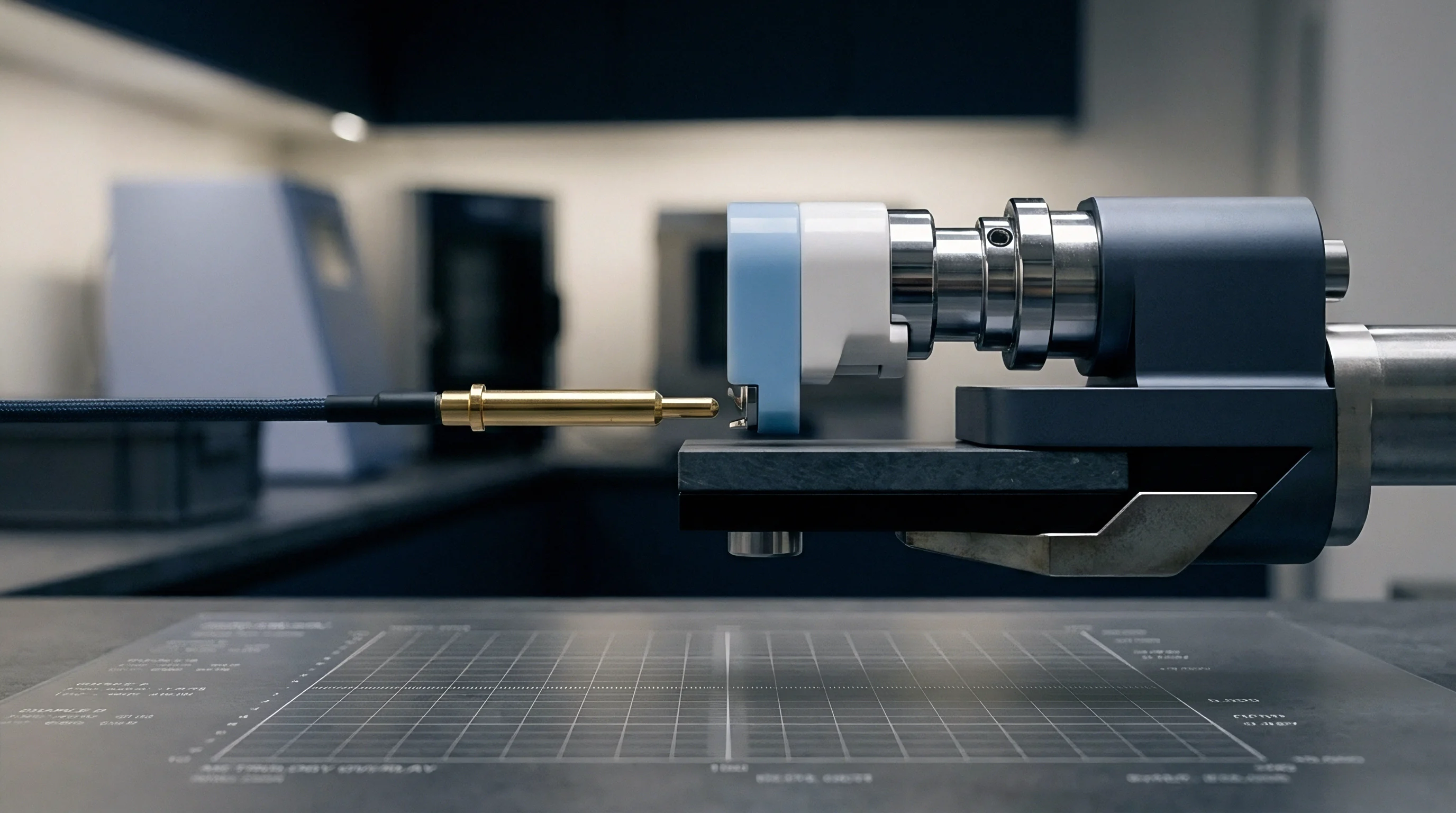
Joint
Joining dissimilar metals leaves complex transition zones vulnerable to localized micro-galvanic attack. Copper-aluminum terminations are typically made using ultrasonic welding, fiber laser welding, or mechanical clinching. Each method alters local microstructure ~ forming solid solutions, supersaturated phases, or discrete intermetallic layers with potentials distinct from the parent metals.
These variations create galvanic micro-cells across the interface that degrade rapidly under mechanical stress and humidity.
Laser welding hits peak temperatures above 1500 degrees Celsius, melting copper and aluminum into a shared pool. Rapid cooling leaves behind brittle intermetallic layers ~ specifically theta phase (Al2Cu), eta2 phase (AlCu), and gamma2 phase (Al4Cu9). Each phase carries its own electrode potential.
Al2Cu shows an open-circuit potential of -0.65 V versus SHE; it is anodic to nickel-plated copper (-0.25 V) but cathodic to the surrounding aluminum alpha-solid solution matrix (-0.85 V). Localized galvanic attack preferentially dissolves the aluminum matrix adjacent to Al2Cu grains, carving micro-trenches along the fusion boundary.
Does Intermetallic Growth Alter Local Polarization Behavior?
Intermetallic growth alters local polarization behavior by introducing hard, brittle phases with poor corrosion resistance. Thermal aging tests show solid-state diffusion continues well below the melting point during routine operation at 45 to 60 degrees Celsius. Over thousands of hours, intermetallic layers thicken according to parabolic growth kinetics:
d_IMC = k_0 exp(-Q / (R T)) sqrt(t)
Here k_0 is the pre-exponential rate constant, Q the activation energy for intermetallic growth (95 to 115 kJ/mol for Cu-Al couples), R the universal gas constant, T absolute temperature, and t operating time. Once the brittle intermetallic layer grows past 2.5 micrometers, thermal cycling cracks it due to thermal expansion mismatch (16.5 x 10⁻⁶ /K for copper versus 23.1 x 10⁻⁶ /K for aluminum). Capillary action pulls condensed moisture into these micro-fissures, forming occluded corrosion cells inside the joint core.
Inside these micro-cracks, occluded cell corrosion accelerates as dissolved metal ions hydrolyze. Aluminum dissolution at the crack tip generates Al3+ cations that hydrolyze directly:
Al3+ + 3 H2O -> Al(OH)3 + 3 H+
Accumulated hydrogen ions drop the crack-tip pH below 2.5, blocking passive oxide reformation. Chloride anions migrate into the fissure to maintain charge neutrality, building concentrated aluminum chloride solutions that consume the load-bearing weld nugget. Joint shear strength drops sharply long before any surface discoloration or salt buildup becomes visible.
Ultrasonic welding avoids bulk melting, using high-frequency vibrations (20 to 40 kHz) under pressure to disrupt surface oxides and form solid-state bonds. Process temperatures stay below 400 degrees Celsius, keeping initial intermetallic layers under 300 nanometers. Severe plastic deformation drives interfacial mixing, producing a dynamic recrystallization zone with sub-micron grains.
Without thick intermetallic layers, ultrasonic welds resist micro-galvanic trenching far better than unoptimized laser welds.
The following sequence tracks the mechanical and electrical breakdown of a compromised dissimilar metal termination over its operating life:
- Moisture Adsorption and Salt Dissolution create an ionic electrolyte film across the exposed perimeter of the bimetallic joint.
- Localized Galvanic Attack dissolves the anodic aluminum matrix directly along the interface seam, generating initial micro-voids.
- Creep-Assisted Interfacial Micro-Cracking propagates under the combined action of road vibration, thermal expansion cycles, and reduced load-bearing area.
- Occluded Cell Acidification drops internal fissure pH below 3.0, accelerating aluminum dissolution inside the joint core.
- Oxide and Hydroxide Precipitation fills internal fissures with non-conductive Al(OH)3 corrosion products, driving contact resistance upward.
- Localized Ohmic Heating triggers thermal runaway at the terminal, destroying the adjacent cell seal and causing final open-circuit failure.
Mechanical clinching and bolted joints introduce crevice geometry without metallurgical bonding. The micro-gap between clamped copper and aluminum sheets acts as a continuous capillary channel that holds moisture. Vibrational fretting wears away protective platings, placing bare copper directly against aluminum under contact pressure.
In unsealed bolted joints exposed to salt spray, contact resistance climbs from 0.8 micro-ohms to over 50 milliohms within 240 hours.
| Joining Technology | Initial Resistance (u-ohm) | Final Resistance (u-ohm) | Initial Shear Strength (kN) | Final Shear Strength (kN) | Dominant Failure Mode |
|---|---|---|---|---|---|
| Direct Laser Weld (Cu to Al) | 1.15 | 84.20 | 2.45 | 0.62 | Intermetallic trenching / brittle fracture |
| Ultrasonic Weld (Cu to Al) | 0.92 | 12.40 | 2.10 | 1.45 | Perimeter galvanic pitting / tab tearing |
| Laser Weld with Ni-Foil Interlayer | 1.05 | 3.10 | 2.60 | 2.25 | Uniform minor surface oxidation |
| Friction Stir Spot Weld (Al to Cu) | 0.88 | 9.80 | 2.80 | 1.90 | Interfacial galvanic rim attack |
| Bolted Joint (Sn-plated Cu to Al) | 1.40 | 1250.00 | 1.80 | 0.30 | Crevice corrosion / bolt torque loss |
Inserting a nickel foil interlayer suppresses intermetallic growth during laser welding. A 50-micrometer pure nickel foil placed between the aluminum tab and copper busbar acts as a thermal and chemical diffusion barrier. Nickel forms stable, less brittle Ni-Al and Ni-Cu phases with smaller potential differences against both parent metals.
Laser power must be tuned carefully to avoid burning through into the copper substrate, keeping the barrier layer intact.
Friction stir spot welding forms solid joints by plasticizing aluminum and mechanically interlocking it into the copper substrate without bulk melting. The rotating pin forces refined aluminum grains into machined grooves on the copper surface. Temperatures stay below 450 degrees Celsius, limiting intermetallic growth to isolated nanometer-scale islands.
The recrystallized stir zone seals the joint core against atmospheric moisture ingress.
Post-weld verification relies on four-wire Kelvin resistance sensing. A resistance shift as small as 0.2 micro-ohms above baseline indicates incomplete acoustic coupling or excessive intermetallic growth. Such defective joints easily pass room-temperature continuity checks, yet fail early under environmental testing.
Engineering drawings require explicit perimeter sealing callouts around the weld nugget. Applying UV-cured dielectric sealants over the weld seam blocks electrolyte access and prevents galvanic cell formation. Without perimeter sealing, bimetallic welds do not survive long-term exposure in humid environments.
A weld nugget resistance increase of 0.5 micro-ohms during pilot qualification correlates with a 65 percent drop in mechanical joint fatigue life under vibrational loading.
Ultrasonic welding requires narrow process windows to retain corrosion resistance. Clamping pressure, vibration amplitude, and energy input interact to control bond density. Too much energy drives the anvil deep into the aluminum tab, creating stress points where galvanic pitting takes hold.
Too little energy leaves unbonded oxide patches that trap moisture and accelerate crevice corrosion.
Modulating laser power via wobble heads offers another path to limit defects. Oscillating the beam in circular or figure-eight patterns distributes heat across the joint, lowering peak pool temperatures, preventing keyhole spatter, and keeping intermetallic growth below 1.5 micrometers across the nugget footprint.
Assembly contact pressure may temporarily crush surface oxides, but chemical breakdown still occurs once humidity penetrates the module casing.
Barrier
Surface plating, conversion coatings, and polymeric barriers represent the three primary defenses against galvanic conductor corrosion. Metallic coatings alter the couple by placing an intermediate electrochemical potential between copper and aluminum. Electroplated nickel on copper busbars is standard; a layer between 3 and 8 micrometers thick protects against corrosion without compromising electrical conductivity or weldability.
The deposit must remain crack-free and low in internal stress to avoid delamination during post-plating bending.
Porosity is the primary failure mode for plated copper busbars. Thin or poorly deposited nickel leaves pinholes that expose raw copper. Under condensed moisture, micro-galvanic cells form between small copper sites and the surrounding nickel cathode.
Rapid pitting perforates the copper substrate, peeling the nickel plating and releasing conductive debris inside the high-voltage enclosure.
Plating quality is assessed using nitric acid vapor and neutral salt spray tests under ASTM B117. Acceptable coatings must show zero pinholes per 100 cm2 after 60 minutes of nitric acid vapor exposure. Technical requirements for protective coatings on high-voltage pack interconnects are summarized below.
| Coating System | Target Thickness (um) | Application Method | Maximum Porosity (pores/cm2) | Dielectric Strength (kV/mm) | Operating Limit (deg C) |
|---|---|---|---|---|---|
| Electroless Nickel (High-P) | 5.0 +/- 0.5 | Chemical Autocatalytic | 0.0 | N/A (Conductive) | 200 |
| Electroplated Matte Sn | 8.0 +/- 1.0 | Electrodeposition | 0.2 | N/A (Conductive) | 120 |
| Electroplated Bright Ni | 4.0 +/- 0.5 | Electrodeposition | 1.5 | N/A (Conductive) | 150 |
| Parylene-C Film | 15.0 +/- 2.0 | Vapor Deposition Polymerization | 0.0 | 220 | 125 |
| UV-Curable Acrylate | 50.0 +/- 5.0 | Selective Robotic Dispensing | 0.0 | 80 | 105 |
| Polyurethane Resin | 120.0 +/- 15.0 | Automated Spray Coating | 0.1 | 60 | 130 |
High-phosphorus electroless nickel (10 to 13 percent phosphorus by weight) yields an amorphous, non-magnetic film with far better corrosion resistance than bright electrolytic nickel. Its amorphous structure lacks the grain boundaries that usually permit electrolyte penetration. Electroless nickel coats complex shapes evenly, including threaded holes and sharp stamped edges where electroplating tends to form heavy edge beads.
Tin plating serves as an economical alternative for busbar terminations. Matte tin avoids the spontaneous conductive whiskers common to bright tin under mechanical pressure. It forms a thin, self-limiting SnO2 oxide that breaks down readily under clamping force, preserving low contact resistance.
However, tin’s low melting point (232 degrees Celsius) requires tight thermal control during welding to prevent reflow outside the joint.
Engineering drawings require explicit plating callouts to prevent unauthorized material substitutions. Specifications should define base metal cleaning, underplate steps, final thickness, thermal shock testing, and porosity limits. Essential callout elements include:
- Base Metal Deoxidation removes surface rolling oils and native copper oxides using acid etching before plating entry.
- Underplate Barrier Deposition applies a 1.5 to 2.0 micrometer ductile copper underlayer to seal substrate porosity on rolled busbar stock.
- Electroless Nickel Deposition coats 5.0 micrometers minimum of high-phosphorus nickel alloy conforming to ASTM B733 standards.
- Hydrogen Embrittlement Relief bakes coated high-strength copper alloy components at 190 degrees Celsius for four hours within three hours of plating completion.
- Automated Optical Inspection scans 100 percent of busbar mating faces for blisters, nodules, pinholes, or edge flaking defects.
Polymeric barriers complement metallic platings by physically sealing the joint. Two-part polyurethane or epoxy potting compounds fill voids around welded tabs, shutting out moisture and oxygen. These materials require low ionic impurity levels ~ under 10 ppm total extractable chloride, bromide, and sulfate ions ~ because high ionic content drives localized corrosion once moisture diffuses through the polymer.
Thermal cycling strains the bond between polymeric encapsulants and metal surfaces. Mismatched thermal expansion coefficients induce shear stress that can delaminate the interface. Once a gap opens, it traps moisture and accelerates galvanic corrosion beneath the potting.
Silane coupling agents improve long-term wet adhesion, preserving the barrier across operating temperatures from -40 to 85 degrees Celsius.
Omitting edge coverage tolerances from a busbar plating print virtually guarantees exposed copper, as assembly handling easily strips electroplated coatings over sharp stamping burrs.

Warranty
Warranty exposure from interfacial conductor corrosion usually surfaces after thousands of operating hours in the field. Interfacial corrosion rarely causes out-of-box failures; instead, it produces a slow rise in contact resistance, localized heating, erroneous BMS voltage readings, and intermittent isolation faults three to seven years into service. Distributing liability across the supply chain requires explicit contractual boundaries for humidity, assembly cleanliness, and joint qualification.
Automotive and grid storage contracts typically mandate 8 to 15 years of defect-free operation. If a module fails open or suffers a thermal event due to joint corrosion, warranty claims expand to recall campaigns, replacement packs, logistics, and root-cause analysis. Clear contractual seams must define where cell supplier responsibility ends, where component quality sits, and where pack assembly takes over.
A contract clause that fails to specify internal module relative humidity limits forfeits the pack builder’s right to reject corroded cells returned from high-humidity operational markets.
Supply agreements rely on qualification protocols to validate interface reliability before mass production. Accelerated testing combines cyclic temperature-humidity profiles (IEC 60068-2-38), salt spray (ASTM B117 or ISO 9227), and operational vibration (UN 38.3 or ISO 16750-3). Qualification requires evaluating electrical contact resistance under full continuous and pulse current loads while tracking localized temperature spikes with embedded thermocouples.
Failure analysis protocols define precise inspection methods to arbitrate disputed warranty claims between cell vendors and pack integrators:
- Four-wire micro-ohm contact resistance measurement across every individual joint before disassembly.
- Pack enclosure helium leak testing to determine if environmental seal failure permitted external water ingress.
- Gas chromatography-mass spectrometry of internal enclosure atmosphere to detect trace electrolyte solvent leakage from damaged cell seals.
- Non-destructive micro-computed tomography scanning to map internal weld nugget porosity and interfacial crack networks.
- Cross-sectional metallurgical polishing and scanning electron microscopy with energy-dispersive X-ray spectroscopy to identify corrosion product chemistry.
- Focused ion beam milling across the joint boundary to measure intermetallic compound layer thickness and verify plating continuity.
Liability disputes often center on identifying the corrosive species inside failed modules. If EDX spectroscopy reveals high chlorine levels on corroded aluminum tabs, scrutiny shifts to pack assembly cleanliness, solder flux residues, or gasket leaks. Conversely, phosphorus and fluorine residues from hydrolyzed LiPF6 electrolyte point to cell manufacturing defects, such as bad terminal seal crimps or cracked ceramic feedthroughs.
Contracts specify acceptable resistance drift over the warranty lifecycle. A typical commercial clause limits total interconnect resistance increase to no more than 15 percent over baseline End-of-Line measurements after 1000 thermal shock cycles (-40 to 85 degrees Celsius) and 500 hours of cyclic damp heat (85 degrees Celsius at 85 percent relative humidity). Joints exceeding this limit are classified as manufacturing defects, assigning replacement and sorting costs back to the vendor.