Finite Element Kinetics for Intermetallic Layer Dissolution in Pack Interconnects
Finite element kinetic modeling of busbar joint intermetallics maps coupled electrothermal dissolution to prevent resistance spikes and joint failure.
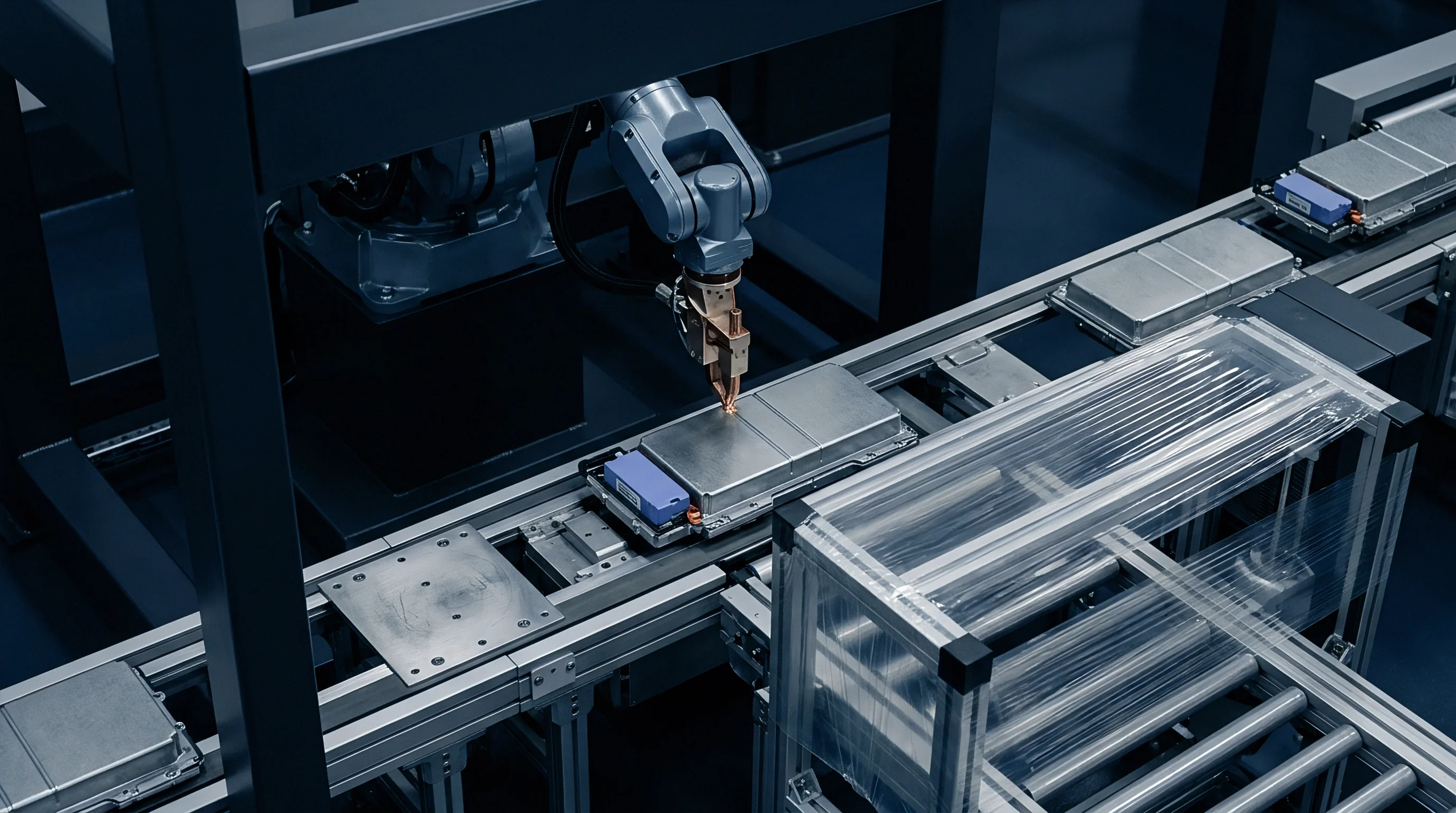

Weld
A 300-micrometer copper tab ultrasonically joined to a 0.5-millimeter aluminum busbar carries 120 amperes continuous peak current across a 4.2-square-millimeter contact area. High local current density at the tab-to-busbar interface generates sharp thermal gradients during heavy discharge cycles. Microstructural evolution begins during the initial joining operation, where solid-state diffusion creates sub-micrometer intermetallic phase zones.
The contact area dictates heating. Thermal spikes exceeding 180 degrees Celsius accelerate atomic transport between dissimilar lattice structures, converting pure metal contacts into complex intermetallic compounds (IMCs) over extended operational lifetimes.
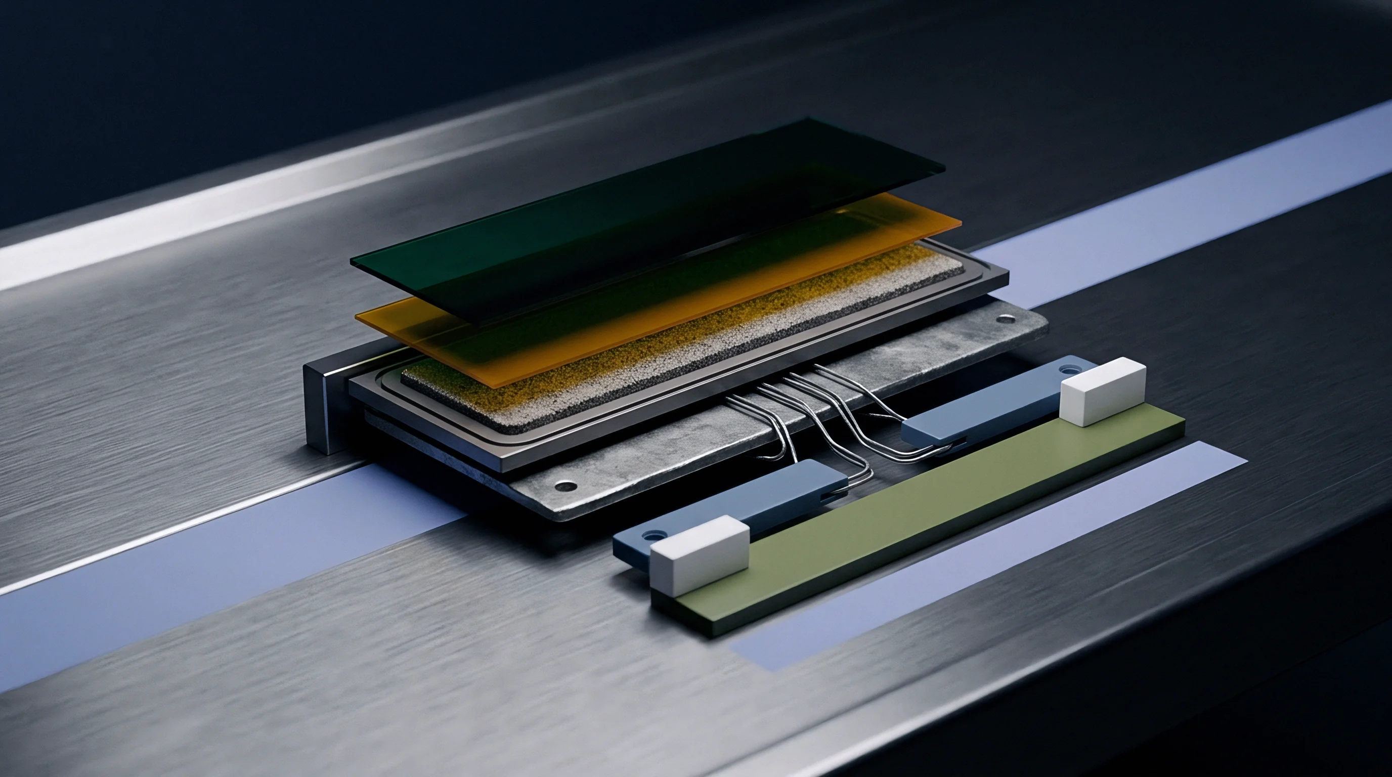
Interfacial Phase Nucleation at Dissimilar Joining Boundaries
Metallic diffusion across heterogeneous metallic interfaces begins during the transient thermal impulse of ultrasonic or optical joining operations. In copper-to-aluminum joints, the initial bonding interface forms a non-uniform layer of intermetallic phases, primarily theta-phase Al2Cu, gamma-phase Cu9Al4, and eta-phase CuAl. Phase nucleation depends on local peak temperature, contact pressure, and plastic deformation intensity during processing.
Pure aluminum and pure copper maintain high electrical conductivity and ductility, whereas interfacial intermetallic phases exhibit significantly higher electrical resistivity and mechanical brittleness.
As the interconnect undergoes thermal cycling during pack operation, solid-state interphase growth continues. Diffusivity across the intermetallic boundaries follows non-linear pathways, driven by both chemical concentration gradients and localized ohmic heating. The thermal energy generated by continuous current flow accelerates phase transformation kinetics, expanding the brittle intermetallic zone thickness from initial values below 0.2 micrometers to post-aging layers exceeding 3.5 micrometers.
Phase composition determines joint resistance and fatigue life under mechanical shock loading.
Solid State Atomic Transport during Laser Pulse Execution
High peak energy input drives rapid localized thermal spikes exceeding 600 degrees Celsius across sub-millimeter contact zones. During laser welding of nickel-plated copper tabs to aluminum prismatic cell terminals, molten pool dynamics dictate initial intermetallic distribution. Fast cooling rates above 10,000 Kelvin per second freeze non-equilibrium phase structures, trapping meta-stable intermetallic compositions along the melt line boundary.
Uncontrolled intermetallic compound growth severely compromises the structural integrity and electrical efficiency of battery pack interconnects. The following failure modes characterize degraded dissimilar metal interfaces:
- Brittle Phase Precipitation occurs when high concentrations of Cu9Al4 or Al3Ni form continuous interfacial sheets, drastically reducing joint shear strength.
- Volumetric Shrinkage Stresses generate internal lattice strain during phase transformation due to molar volume mismatches between pure metals and intermetallic compounds.
- Resistive Heating Escalation drives localized thermal runaways as the higher resistivity of intermetallic layers increases total interconnect voltage drop.
- Interfacial Delamination promotes complete electrical open circuits when micro-cracks propagate along high-hardness, low-toughness intermetallic boundaries.
Quantifying physical properties across dissimilar metal phase layers is essential for predicting degradation rates in finite element models. Table 1 summarizes the crystallographic, electrical, and mechanical properties of common intermetallic phases formed in copper-aluminum and nickel-aluminum interconnect joints.
| Phase Composition | Crystal Structure | Density (g/cm³) | Resistivity (µΩ·cm) | Youngs Modulus (GPa) | Vickers Hardness (HV) |
|---|---|---|---|---|---|
| Pure Copper (Cu) | FCC | 8.96 | 1.68 | 120 | 65 |
| Pure Aluminum (Al) | FCC | 2.70 | 2.65 | 70 | 25 |
| θ-Al2Cu | Tetragonal | 4.34 | 8.00 | 107 | 380 |
| γ-Cu9Al4 | Cubic | 6.85 | 14.20 | 145 | 540 |
| η-CuAl | Monoclinic | 5.35 | 11.40 | 122 | 460 |
| Al3Ni | Orthorhombic | 3.95 | 13.10 | 130 | 410 |
| Ni3Al | Cubic | 7.50 | 32.50 | 178 | 280 |
Failing to account for initial intermetallic layer thickness in laser or ultrasonic joint setup guarantees premature fatigue cracking across the busbar array under field vibration loads.


Morphology
Interfacial compound growth follows parabolic rate kinetics under steady isothermal aging conditions. Phase transformation rates accelerate under dynamic electric fields due to continuous atomic flux interactions. In battery pack interconnects, the growth of intermetallic layers alters the geometric cross-section of pure metal conductors, altering local mechanical compliance and impedance performance.

Phase Evolution Kinetics under Isothermal and Cycling Load
Thermal exposure accelerates atomic mobility across the metallurgical boundary between copper and aluminum. Solid-state diffusion kinetics dictate that layer thickness (x) increases with time (t) according to the parabolic relation x² = k · t, where k represents the temperature-dependent reaction rate constant. The temperature dependence of k obeys an Arrhenius formulation, k = k0 · exp(-Q / (R · T)), where k0 is the pre-exponential frequency factor, Q is the activation energy for phase growth, R is the universal gas constant, and T is absolute temperature.
In copper-aluminum interconnects, activation energies for phase growth range from 68 kJ/mol to 112 kJ/mol depending on specific phase stoichiometry and grain boundary density. During high-current pulse operations, localized temperature spikes drive non-isothermal diffusion, generating transient growth bursts that exceed steady-state thermal predictions. Continuous temperature swings between negative 40 degrees Celsius and positive 85 degrees Celsius induce cyclically varying diffusion coefficients, leading to heterogeneous phase thickening along stress-concentrated regions.
At 85 degrees Celsius under continuous 40 ampere current flow, the interfacial Al2Cu layer thickens at 1.4 nanometers per hour, doubling bulk contact resistance after 1,200 thermal hours.

Kirkendall Vacancy Accumulation and Micro-Cavitation
Asymmetric diffusion coefficients between constituent metals create an unbalanced flux of lattice vacancies toward the faster-diffusing species. In the copper-aluminum system, copper atoms diffuse into aluminum faster than aluminum atoms migrate into copper at operational temperatures. This net flux inequality causes vacancy supersaturation on the copper-rich side of the interface, inducing Kirkendall void formation.
Kirkendall voids coalesce over thousands of electrical charge-discharge cycles into continuous microscopic cavities. Micro-cavitation reduces the effective metallurgical load-bearing area, increasing local stress intensity factors under mechanical strain. Brittle phases crack under stress.
Furthermore, these void arrays act as electrical barriers, forcing current through narrow metal bridges and intensifying local Joule heating in a self-reinforcing degradation loop.
Consider a finite element kinetic model evaluating intermetallic growth and resistance growth across a 100-micrometer ultrasonic joint under three distinct thermal operating regimes over 3,000 thermal cycling hours. At a continuous joint temperature of 45 degrees Celsius, the intermetallic layer thickness increases from 0.15 micrometers to 0.68 micrometers, yielding an absolute electrical resistance increase of 1.2 micro-ohms. Elevating operating temperature to 65 degrees Celsius pushes final intermetallic thickness to 1.85 micrometers, raising joint resistance by 4.8 micro-ohms.
Under a severe thermal profile of 85 degrees Celsius, intermetallic thickness reaches 4.32 micrometers, increasing joint resistance by 16.5 micro-ohms and initiating micro-cavitation along the Al2Cu-copper interface. Kinetic finite element modeling must capture this exponential sensitivity to temperature to yield valid pack service-life predictions.
Predicting joint lifetime requires evaluating Kirkendall void density alongside total intermetallic layer growth, because interfacial micro-cavitation degrades mechanical fatigue resistance far more rapidly than total phase thickness growth alone.
Flux
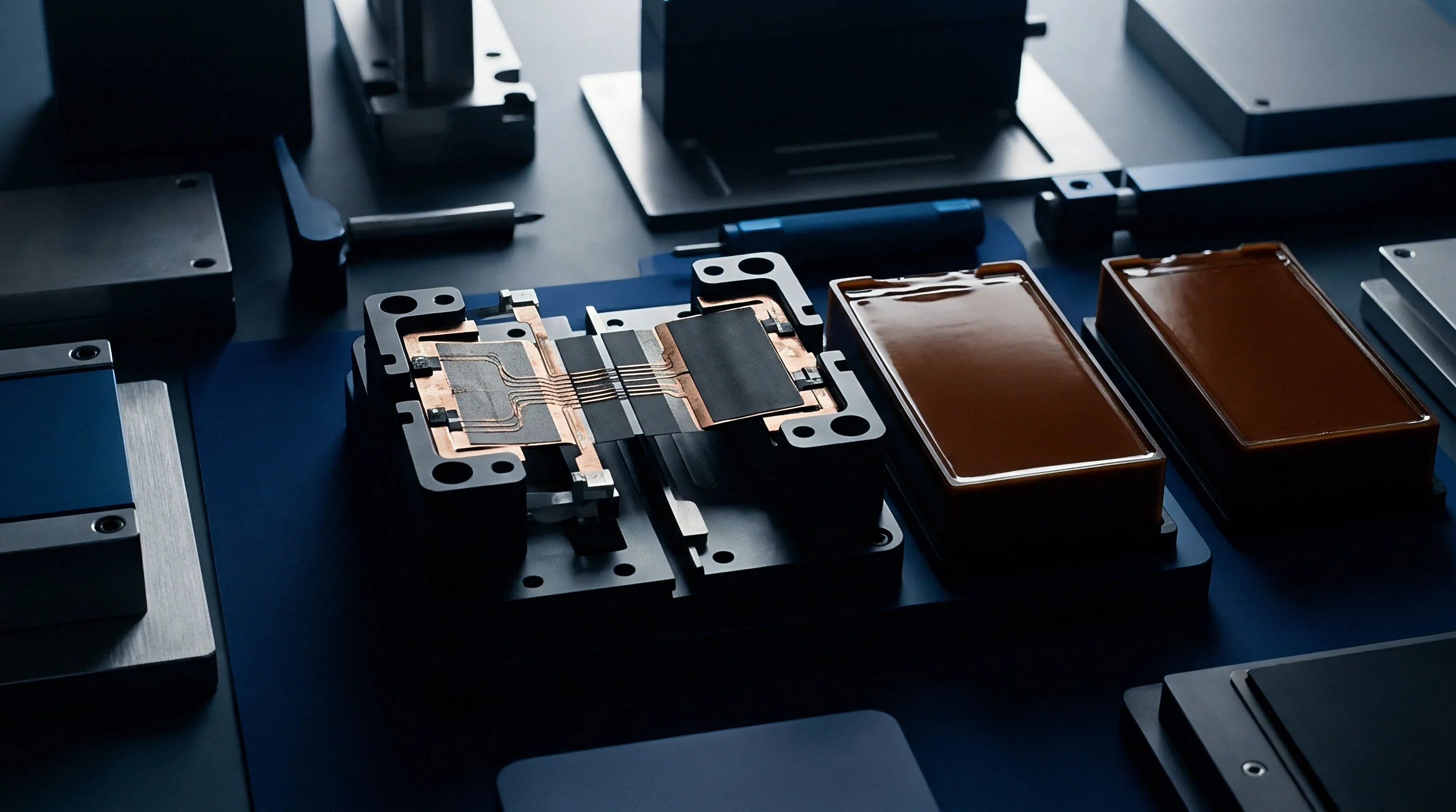
Multiphysics numerical formulations require simultaneous solution of electric potential, temperature field, and mass transport equations. In high-power battery packs, interconnected tab geometries experience coupled driving forces that force atomic transport. High current densities introduce electromigration momentum, while steep thermal gradients drive thermomigration across tiny interfacial dimensions.
Electro-Thermal-Diffusion Coupled Field Differential Governing Equations
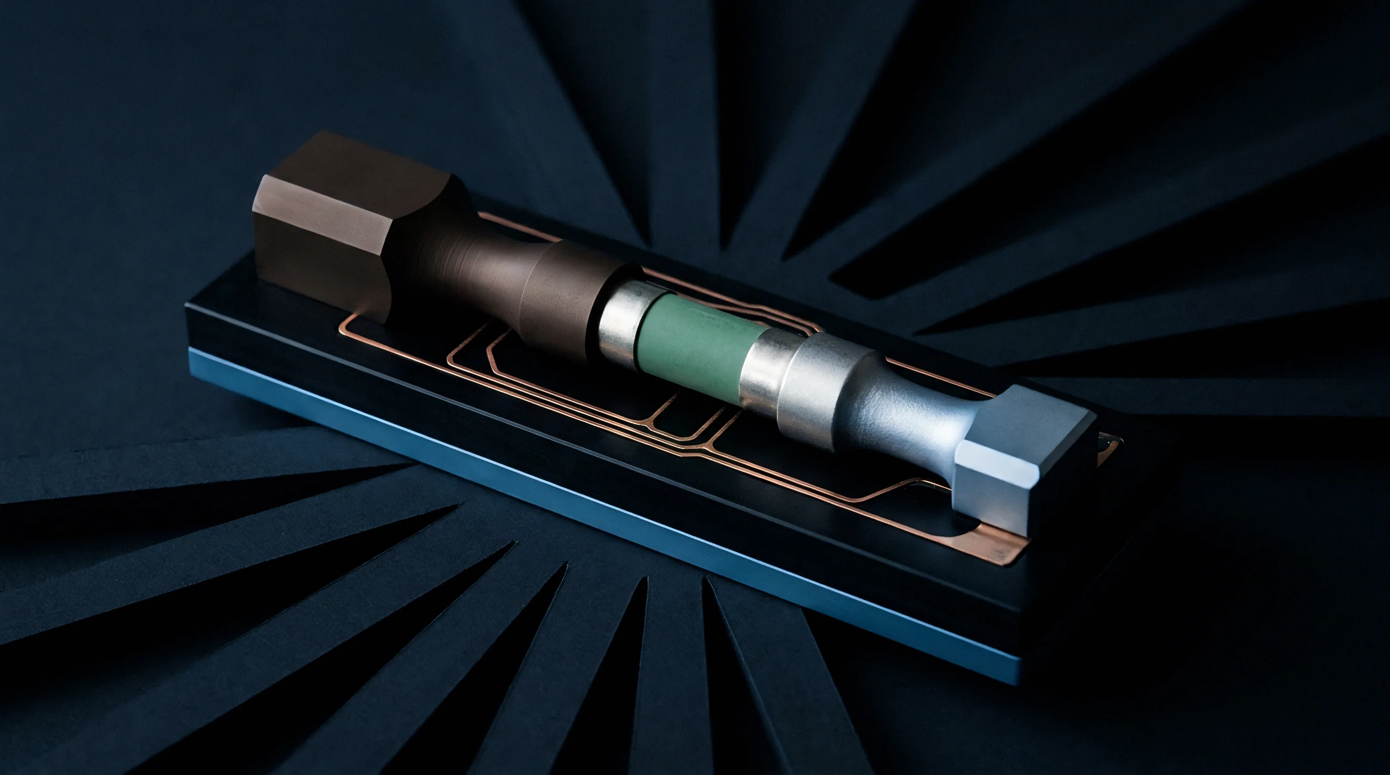
System state variables resolve through partial continuum equations linking current conduction directly to heat production. Electric field distribution is governed by Laplace’s equation for scalar potential, divergence of (sigma grad V) equals zero, where sigma is temperature-dependent electrical conductivity and V is electrical potential. Current density vector j equals negative sigma grad V. Local heat generation q equals j dot E, which serves as the volumetric heat source in the heat conduction equation, density times specific heat times partial T with respect to t equals divergence of (k grad T) plus q, where k is thermal conductivity and T is temperature.
Atomic flux (J) incorporates concentration-driven Fickian diffusion, electromigration flux, and thermomigration flux into a unified mass transport model:
J = -D · ∇C + C · (D / (k_B · T)) · (Z · e · E – (Q / T) · ∇T)
In this governing equation, D represents temperature-dependent interdiffusivity, C is atomic concentration, k_B is Boltzmann’s constant, Z is the effective charge number for electromigration, e is elementary charge, E is electric field intensity, and Q is the heat of transport for thermomigration. Atomic flux follows voltage drop. Thermal gradients drive phase migration.
The divergence of atomic flux determines localized concentration changes over time through mass conservation, partial C with respect to t equals negative divergence of J. Finite element frameworks solve these governing equations simultaneously at every mesh node.
IEC 62660-2 clause 6.2 rejects busbar interconnect assemblies that exhibit localized electrical resistance growth exceeding 15 percent following 500 thermal shock cycles.

Current Density Concentration at Edge Radius Boundaries
Geometric discontinuities in ribbon tab geometries force electron flow through constricted cross-sectional channels. Current crowding occurs at sharp internal radii, weld notch corners, and perimeter boundaries of spot welds. Local current densities at these geometric bottlenecks frequently reach magnitudes five to ten times higher than the average current density calculated across the nominal contact patch.
Local current peaks alter transport. Current crowding intensifies both local Joule heating and electromigration forces. High electron wind forces knock copper and aluminum ions along direction vectors aligned with electron flow, shifting interfacial phase boundaries faster than thermal diffusion alone would dictate.
Finite element simulations demonstrate that localized intermetallic dissolution and growth rates at weld edge radii exceed center-zone rates by more than 300 percent, creating non-uniform phase profiles that induce severe local stress concentrations.
Welding subcontractors frequently claim that minor interconnect resistance increases observed during thermal-shock screening represent harmless bulk annealing of the tab material, ignoring the localized intermetallic layer thickening occurring at current-crowded joint edges.


Discretization
Numerical modeling of sub-micrometer reaction zones demands spatial resolution capable of capturing steep concentration gradients. Modeling intermetallic phase layer kinetics in finite element solvers requires adaptive spatial grids that resolve chemical transitions spanning less than 50 nanometers without causing computational instability or high memory consumption across full battery module domains.
Can Phase Field FEA Predict Kirkendall Voiding at High Current Density?
Continuum mathematical models map non-uniform concentration variables across diffusely defined phase interfaces without explicit surface tracking. The phase-field method uses conserved order parameters (representing atomic concentration) and non-conserved order parameters (representing local phase structural symmetry) to simulate interface evolution. Free energy functionals combine chemical energy density, gradient energy terms, and elastic strain energy contributions to drive phase transformations under multi-field loading.
Phase-field kinetic simulations capture complex morphology changes including intermetallic grain growth, phase dissolution, and Kirkendall void nucleation simultaneously. By coupling lattice vacancy concentrations to the phase-field free energy equations, finite element solvers model the nucleation of micro-cavities where local vacancy supersaturation exceeds critical thermodynamic thresholds. Fine elements resolve narrow gradients.
Coarse grids mask boundary movement. When parameterized with accurate atomic mobility data, phase-field FEA accurately predicts the formation and spatial distribution of interfacial voids under high direct current densities.
- Define geometry and apply a localized mesh refinement zone of 50 nanometers along the interconnect bonding plane.
- Assign phase-dependent thermal conductivity, electrical resistivity, and diffusivity tensors to copper, aluminum, and intermediate intermetallic phases.
- Set boundary conditions for electrical current pulse, ambient thermal sink, and voltage gradient across tab contacts.
- Execute coupled implicit step solver to evaluate local current crowding and temperature evolution across the interfacial boundary.
- Update phase concentration field variables dynamically to track intermetallic layer growth rate and Kirkendall void accumulation.
Subroutine Formulation for Moving Interphase Boundary Tracking
Custom code blocks written in FORTRAN or C language interface directly with implicit continuum solvers. In commercial finite element platforms, subroutines like UMESHMOTION or USDFLD dynamically re-mesh element nodes at phase boundaries based on interdiffusivity rates calculated during each time step. Moving boundary algorithms track the shift of the phase boundary matrix, continuously updating element material properties as pure metals dissolve into intermetallic compounds.
Temporal discretization requires strict time-step control to maintain stability in parabolic reaction-diffusion equations. Explicit integration schemes demand extremely small time steps governed by the Courant-Friedrichs-Lewy criterion, where time increments must scale with the square of the smallest element dimension. Implicit backward-Euler solvers allow larger time steps but require iterative Newton-Raphson solvers to achieve convergence across non-linear material properties.
Table 2 presents mesh convergence and stability parameters for transient interconnect interface simulations.
| Interface Mesh Size (nm) | Element Type | Time Step Scheme | Max Time Step (s) | Concentration Error (%) | Compute Time per 1,000 Cycles (h) |
|---|---|---|---|---|---|
| 500 | Linear Quad (CPE4) | Explicit Euler | 0.001 | 14.2 | 0.8 |
| 200 | Linear Quad (CPE4) | Implicit Euler | 0.100 | 6.5 | 2.4 |
| 50 | Quadratic Quad (CPE8) | Implicit Euler | 0.050 | 1.1 | 18.6 |
| 10 | Quadratic Quad (CPE8) | Adaptive Implicit | 0.010 | 0.2 | 142.0 |
What spatial discretization limit balances computational runtime against phase-growth prediction accuracy when modeling multi-tab busbars across a 96-cell series pack configuration?
Calibrations
Physical validation of numerical kinetic models relies on precise microstructural characterization and micro-ohmic measurement. Abstract phase-growth equations produce inaccurate lifetime estimates unless micro-architectural diffusivity parameters, activation energies, and phase resistivity constants are calibrated against physical aging datasets obtained from actual interconnect cross-sections.
Microstructural Verification via Cross-Sectional Spectrometry
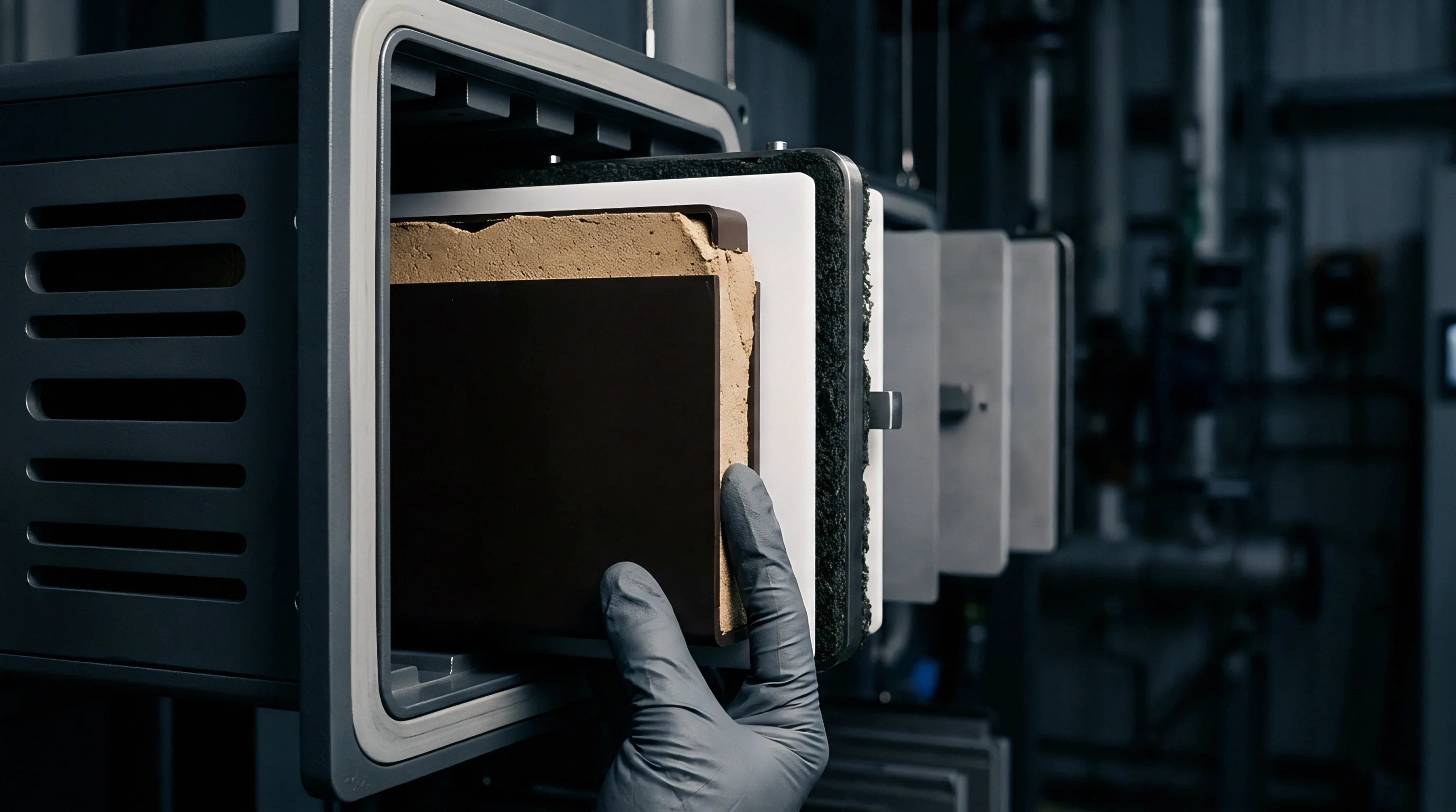
Focused ion beam milling exposes undisturbed structural planes across the bimetallic joint boundary. Scanning electron microscopy (SEM) paired with energy-dispersive X-ray spectrometry (EDS) quantifies elemental concentration profiles across intermetallic layers. Transmission electron microscopy (TEM) identifies specific crystallographic phases (such as Al2Cu vs Cu9Al4) by analyzing selective area electron diffraction (SAED) patterns across sub-micrometer grains.
Teardown data confirms layer growth. Experimental phase thickness measurements taken at discrete aging intervals (such as 250, 500, and 1,000 hours at elevated temperatures) provide empirical data points to calibrate FEA kinetic growth coefficients. Nanoindentation mapping across joint cross-sections measures local elastic modulus and hardness gradients, confirming phase identity and revealing brittle zones prone to micro-cracking.
Calibrating transient numerical models against actual joint degradation requires micro-ohmic resistance tracking at constant ambient temperature to isolate interfacial phase growth from bulk thermal expansion effects.

High Frequency Resistance Drift Matching Protocols
Four-wire Kelvin sense lead arrangements capture sub-micro-ohm impedance alterations during continuous environmental stress testing. Standard two-wire resistance measurements lack sufficient resolution to detect nanometer-scale intermetallic layer growth. Resistance tracking during environmental cycling reveals the onset of phase transformations and micro-cavitation long before mechanical joint failure occurs.
Physical validation protocols require isolating thermal resistivity effects from phase-change resistivity. Resistance measurements must be taken at isothermal reference temperatures (typically 20 degrees Celsius) after specific thermal aging exposure blocks. Resistance rises as voids grow.
Comparing finite element predicted resistance growth curves against measured micro-ohmic drift curves enables exact calibration of effective diffusivity tensors and electromigration reaction rates in the simulation model.
A structured decision framework validates finite element kinetic predictions against physical test samples:
- Cross-Sectional Microscopy Calibration confirms that predicted intermetallic phase layer thickness matches observed SEM cross-section dimensions within a 5 percent margin.
- Four-Point Micro-Ohm Tracking isolates physical joint resistance changes during thermal aging to validate phase resistivity parameters implemented in the numerical solver.
- Diffusivity Parameter Verification determines activation energy constants from isothermal aging trials to adjust pre-exponential kinetic factors in custom subroutines.
- Mechanical Strength Correlation maps FEA predicted Kirkendall void fraction against post-aging shear stress test failures to set critical damage threshold values.
According to UN 38.3 section 38.3.4.3, battery assemblies undergoing vibration testing must maintain continuous electrical continuity without joint impedance fluctuations exceeding specified tolerance thresholds, establishing physical compliance baselines for calibrated numerical models.


Settlement
Commercial pack specifications translate numerical degradation curves into warranty duration metrics and supplier quality clauses. Engineering pack interconnects requires balancing initial tooling investments and material expenses against long-term liability exposure arising from interconnect resistance growth and pack field failures.

Interconnect Life Warranties and Sourcing Responsibility Boundaries
Long-term pack failure liabilities depend on defining clear operational envelopes for maximum interconnect temperature and peak current spikes. Cell manufacturers, pack integration assembly houses, and vehicle original equipment manufacturers (OEMs) frequently dispute joint failure ownership. Pack integrators assert that cell tab plating variations drive excess intermetallic growth, while cell suppliers blame improper laser welding heat input or aggressive pack discharge profiles.
Tooling drift shifts weld profile. Contract terms assign joint risk. Clear engineering specifications mandate maximum allowable intermetallic compound thickness (typically capped at 1.5 micrometers for Cu-Al joints) upon receipt of welded modules.
Finite element kinetic kinetics models establish baseline performance envelopes, allowing procurement teams to write verifiable quality acceptance limits into supplier contracts.
Specifying a maximum allowable contact resistance drift rate in the interconnect supply contract transfers non-linear thermal degradation risks directly to the welding subcontractor.

NRE Tooling Tolerances and Qualification Rejection Thresholds
Non-recurring engineering quotes for automated busbar welding lines include optical monitoring and process window boundaries. Yield loss drives landed expense. Tight tolerances lower pack failure.
Automated inline process monitoring—such as laser weld optical emission spectrometry or ultrasonic acoustic signature analysis—detects improper melt depth and thermal energy input that cause excessive initial intermetallic nucleation.
Selecting appropriate joint metallurgy involves commercial trade-offs between tooling NRE costs, initial unit expense, and 10-year field warranty risk. Table 3 presents an economic and operational comparison of common high-current interconnect metallurgy combinations.
| Metallurgy System | Initial Tooling NRE (USD) | IMC Growth Susceptibility | 10-Year Resistance Drift Risk | Warranty Exposure Index |
|---|---|---|---|---|
| Direct Ultrasonic Cu-Al | 120,000 | High | High (15-35% rise) | High |
| Laser Welded Direct Cu-Al | 350,000 | Very High | High (20-45% rise) | Very High |
| Nickel-Clad Intermediate Tab (Cu-Ni-Al) | 220,000 | Low | Low (3-8% rise) | Low |
| Bimetallic Friction-Welded Transition Busbar | 180,000 | Moderate | Moderate (8-14% rise) | Moderate |
| Note: Warranty exposure index reflects potential field failure liability based on predicted 10-year thermal degradation under continuous 1.5C cycling profiles. | ||||
Amortizing specialized joining tooling over production volumes requires calculating the total landed cost of joint reliability across the full product lifecycle. Incorporating validated finite element intermetallic dissolution models into early RFQ engineering reviews prevents costly tooling retrofits, protects brand equity against field thermal incidents, and locks in predictable warranty reserves before mass production bring-up begins.