Predictive Finite Element Modeling of Mechanical Microstructural Separator Creep under Thermal Transient Stress
Microstructural FEA proves thermal transient stress accelerates separator creep collapse, demanding strict cell stack pressure limits to prevent micro-shorts.


Mesh
Focused ion beam scanning electron microscopy supplies the raw three-dimensional voxel data needed to build exact geometric representations of wet-process polyethylene and dry-process polypropylene separators. Polyolefin membranes feature intricate webbed microstructures with pore diameters ranging from twenty to two hundred nanometers and strut thicknesses between ten and fifty nanometers. Discretizing these spatial domains demands high elemental resolution to capture local stress concentrations during mechanical loading.
Standard continuum modeling techniques that assume isotropic spatial properties obscure localized shear zones and over-predict structural stiffness by treating solid struts and void space as a homogenized continuum.
Representative volume elements must contain enough interconnected pore branches to mirror the bulk mechanical response of the membrane. A volumetric domain measuring ten micrometers on each side provides statistical equivalence to the bulk substrate while remaining computationally tractable for implicit finite element solvers. Microstructure-explicit models translate segmentation threshold data into solid tetrahedral meshes, where node placements align directly with polymer phase boundaries.
Strut intersections act as primary stress risers under applied compressive forces. High surface-to-volume ratios in stretched polymer fibrils require structured meshing algorithms to prevent element distortion when strain levels exceed five percent.
Under tensile loads, individual pore struts collapse.
Thermal transient stress fields generated during aggressive C-rate discharge or localized micro-short events introduce steep temperature gradients across the separator thickness. A temperature surge of fifty degrees Celsius occurring within two hundred milliseconds induces rapid thermal expansion in the adjacent metallic current collectors. Squeezed between expanding graphite anodes and lithium metal oxide cathodes, the separator layer encounters a combination of transverse mechanical compression and transient thermal expansion.
Spatial discretization strategies require coupled thermal-displacement solid elements capable of computing linear thermal expansion alongside mechanical deformation at every step. Resolving non-linear thermal gradients across a separator thickness of sixteen to twenty-five micrometers without numerical oscillation requires at least twelve element layers.
| Substrate Chemistry | Manufacturing Process | Mean Porosity (%) | Strut Diameter (nm) | Target Element Size (nm) | RVE Edge Length (µm) |
|---|---|---|---|---|---|
| Polyethylene (PE) | Wet-Process Stretched | 42 ± 3 | 18 ± 4 | 3.5 | 8.0 |
| Polypropylene (PP) | Dry-Process Uniaxial | 36 ± 2 | 32 ± 6 | 5.0 | 10.0 |
| Trilayer (PP/PE/PP) | Co-Extruded Stretched | 39 ± 3 | 24 ± 5 | 4.0 | 12.0 |
| Alumina-Coated PE | Wet-Process / Dip-Coat | 40 ± 4 | 20 ± 4 | 3.0 | 8.0 |
Teardown analysis of pouch cells exposed to fast-charging transients reveals microstructural pore occlusion occurring at temperatures thirty degrees below the dry polymer melting point. Localized mechanical squeezing forces the soft, amorphous regions of the polyolefin matrix into void channels long before global heat distribution triggers gross thermal shrinkage. Numerical simulations using coarse grids fail to detect these local blockages because spatial averaging dilutes localized strain peaks.
FEA models using sub-five-nanometer element edge lengths predict local pore collapse under 0.8 MPa transverse compression at 85 °C, whereas homogenized models show structural integrity up to 130 °C.
Mapping high-frequency thermal transient data into the mechanical mesh demands temporal step control tied directly to thermal diffusion times. Linear hex-dominated elements yield superior stress accuracy along fibril axes compared to linear tetrahedrons, which suffer from shear locking under heavy bending loads. Quadratic tetrahedral elements offer improved bending compliance but increase node counts by an order of magnitude, causing severe memory bottlenecks when scaling from single representative volume elements to full cell-layer stack assemblies.

Representative Volume Element Construction for Porous Substrates
Constructing a digital twin of semi-crystalline polymer networks begins with binarized X-ray nanotomography or micro-CT dataset slices. Image filtering removes acquisition noise before marching cubes algorithms trace the complex solid-fluid boundaries. Fibrils formed during the orientation stretching phase align predominantly along the machine direction, giving dry-process membranes distinctly anisotropic mechanical moduli.
The longitudinal elastic modulus often exceeds the transverse modulus by a factor of four. Solid geometry reconstruction tools clean degenerate surface triangles, stitching contiguous volumes into closed manifold solids ready for boundary mesh generation.
Zero-thickness cohesive zone elements embedded along polymer domain boundaries track micro-tear propagation under extreme transverse strain. When internal cell stack pressure rises due to gas evolution or anode swelling during lithiation, microstructural struts endure multi-axial tension and shear. Setting the element edge length across strut bridges to fifty nanometers captures strain localization accurately.
Mesh sensitivity analysis confirms that element edge lengths above eight nanometers artificially damp stress peaks, creating a false indication of structural margin during sudden thermal excursions.

Thermal Gradient Discretization and Nodal Interpolation
Transient heat flux across cell layers demands tight integration between thermal transfer equations and structural solver meshes. Thermal conductivity in porous polyolefins depends directly on local void fraction, as liquid electrolyte filling the pores exhibits a thermal conductivity near 0.15 W/m·K, while solid polyethylene carries approximately 0.42 W/m·K. As mechanical strain reduces local porosity, the effective thermal conductivity changes dynamically within each element. Finite element codes update spatial thermal conductivities at every iteration step using microstructural porosity state variables.
Gaps in input data degrade model predictive power.
Boundary conditions applied to the microstructural volume element must reflect macro-scale cell stack restraints. Periodic boundary conditions applied to opposing faces of the representative volume element enforce deformation continuity, preventing artificial edge effects from distorting local stress distributions. Transient heat pulses injected through boundary nodes simulate localized exothermic reactions from solid-electrolyte interphase decomposition.
Thermal stress gradients develop rapidly across strut cross-sections, driving localized creep deformation long before bulk cell temperature sensors register thermal escalation.
During thermal ramp tests, microstructural pore collapse is often characterized as standard thermal shutdown behavior rather than mechanical failure. However, localized mechanical thinning under stack pressure can fall outside standard product specification limits, shifting channel shorting risks onto external pack integration parameters rather than material deformation limits.

Viscoelasticity
Semi-crystalline polyolefins display pronounced time-dependent deformation characteristics that escalate non-linearly with elevated temperature. Below the glass transition temperature, amorphous polymer chains retain rigid configurations, restricting mechanical response to short-term elastic deformation. As operational temperatures approach sixty degrees Celsius, active thermal agitation mobilizes amorphous domains, initiating rapid viscoelastic relaxation and creep under sustained compressive stack loads.
Finite element modeling of these phenomena requires constitutive formulations that blend elastic springs and viscous dashpots in multi-mode Maxwell or Prony series configurations.
Stress relaxation reduces internal stack pressure over extended operating periods, but rapid temperature transients invert this dynamic. Thermal expansion pulses induce transient compressive stress spikes that drive immediate creep deformation in mobile polymer chains. Classical linear viscoelasticity theory assumes strain amplitudes remain sufficiently low to keep stress linearly proportional to strain rate.
Transient mechanical loading during thermal events breaches this linear regime, demanding non-linear viscoelastic models that incorporate stress-dependent activation energy terms.
Under sustained stress, polymer chains slide.
Time-temperature superposition principles apply shift factors to translate long-term creep behavior measured at ambient conditions to rapid high-temperature events. The Williams-Landel-Ferry equation models structural relaxation behavior near the glass transition point, while Arrhenius shift equations govern creep mechanisms at elevated operating temperatures. Activation energy values for wet-process polyethylene creep range between 80 and 110 kJ/mol depending on crystalline fraction and molecular weight distribution.
Accurately modeling high-strain rates under thermal transient stress requires recalibrating activation energy values across high temperature bands to prevent structural over-prediction.
| Prony Mode Number | Relaxation Time Tau (s) | Normalized Shear Modulus Gi | Normalized Bulk Modulus Ki | Temperature Shift Factor Model |
|---|---|---|---|---|
| 1 | 1.0E-03 | 0.285 | 0.250 | Arrhenius (Ea = 92 kJ/mol) |
| 2 | 1.0E-02 | 0.210 | 0.200 | Arrhenius (Ea = 92 kJ/mol) |
| 3 | 1.0E-01 | 0.165 | 0.150 | Arrhenius (Ea = 92 kJ/mol) |
| 4 | 1.0E+00 | 0.120 | 0.110 | Arrhenius (Ea = 92 kJ/mol) |
| 5 | 1.0E+01 | 0.085 | 0.080 | Arrhenius (Ea = 92 kJ/mol) |
| Long-Term Elastic Limit | Infinity | 0.135 | 0.210 | Not Applicable |
Evaluating solver residuals at every thermal step captures phase changes within amorphous domains. Standard finite element codes that rely on static elastic moduli underestimate total separator strain by up to four hundred percent during thermal ramp conditions exceeding ten degrees Celsius per second.
According to UN 38.3 test protocols, cell enclosures subjected to thermal shock cycling must maintain internal mechanical isolation; separator creep deformation under combined 0.5 MPa compression and 72 °C thermal holds directly voids compliance if internal micro-shorts develop.
Constitutive equations governing non-linear creep incorporate Eyring formulation concepts, where applied mechanical stress lowers the activation energy barrier for molecular chain slip. Yield limits drop with heat. High compressive stress combined with rapid thermal expansion drives the separator into tertiary creep, where microstructural necking and fibril rupture occur within seconds, long before global material melting begins.

Nonlinear Creep Formulation under Transient Temperature Fields
Implicit dynamic solvers implement non-linear viscoelastic constitutive laws using incremental state variable formulations. Strain tensors divide into instantaneous elastic, viscoelastic, and permanent plastic components. The instantaneous elastic response follows anisotropic Hookean elasticity derived from oriented polymer fibril orientations.
Viscoelastic strain components evolve through convolution integrals computed across time step increments, updating internal stress values through recursive algorithm schemes.
Steep thermal gradients drive local stress.
Temperature fluctuations alter material viscosity non-linearly across transient heating cycles. Incorporating temperature dependence directly into dashpot viscosity expressions prevents numerical divergence during sudden thermal spikes. Explicit integration schemes demand microscopic time step sizes down to nanosecond intervals to maintain stability when material stiffness drops precipitously during local heating events.
Numerical simulations must monitor kinetic energy against internal energy ratios to prevent dynamic inertia artifacts from distorting slow mechanical creep trends.
Accounting for stress relaxation in constitutive equations tracks residual clamping pressure across the active cell stack. As compression pads relax, structural support decreases, allowing localized separator bulging into adjacent gas expansion gaps or electrode edge cutouts. Separators deform under combined loads, shifting local current density distributions and accentuating electro-thermal hotspot formation during fast recharge cycles.
The operational modes governing high-temperature polymer relaxation follow an established sequence:
- Amorphous chain mobilization initiates elastic modulus degradation as operational temperatures exceed fifty degrees Celsius, softening inter-crystalline tie molecules.
- Compressive creep consolidation flattens porous fibrils into adjacent void channels under sustained cell stack restraint pressures.
- Crystalline lamellae slip occurs under peak shear stress, causing irreversible plastic orientation changes in load-bearing polymer struts.
- Fibril necking breakdown marks the onset of tertiary creep, terminating in localized structural tearing and direct inter-electrode contact.

Time Temperature Superposition and Activation Energy Extraction
Master curve construction for polyolefin separator membranes relies on dynamic mechanical thermal analysis data collected across wide frequency spectrums and stepped temperature profiles. Storage and loss moduli curves shift horizontally along the frequency axis to form smooth composite curves referenced to twenty-five degrees Celsius. Experimental shift factors fit Arrhenius relationships at temperatures below polymer melting points, yielding distinct activation energy values for machine direction tension versus transverse compression.
Determining activation energies under multi-axial stress states requires specialized bi-axial creep testing apparatus integrated with environmental temperature chambers. Compressive activation energies typically run lower than tensile activation energies because hydrostatic pressure components alter free volume availability within amorphous polymer domains. Modeling programs that utilize isotropic tensile creep parameters for transverse compression analysis underestimate pore closure rates under thermal stress regimes.
Static stack pressure combined with thermal transients accelerates physical aging mechanisms inside polyolefin substrates. A safety margin defined solely by static room-temperature tensile strength offers zero protection against creep-induced thinning during thermal runaway propagation events.

Closure
Pore volume loss directly impairs ionic transport through the separator membrane during thermal transient stress events. As mechanical compression forces polymer struts into void channels, tortuosity increases drastically, restricting lithium ion diffusion pathways through the electrolyte-saturated network. Electrolyte migration resistance scales inversely with porosity raised to the power of the MacMullin number exponent, typically ranging between 1.8 and 2.5 for polyolefin separator geometries.
A fifty percent reduction in local porosity doubles effective ionic resistivity, triggering severe localized Joule heating during current flow.
Unchecked stack pressure destroys internal porosity.
Localized thermal-mechanical feedback loops create destructive run-away conditions inside the cell stack. High local current density generates rapid Ohmic heat, raising localized temperature. Rising temperature lowers polymer flow stress, accelerating microstructural creep under static mechanical pre-load.
Microstructural creep further compresses pores, reducing local ionic conductivity and spiking local electrical resistance. Local hot spots form rapidly.
| Porosity Retention (%) | Effective Tortuosity Factor | Ionic Conductivity (mS/cm) | Local Heat Generation Rate (kW/m³) | Creep Strain Rate (1/s) at 0.8 MPa, 95 °C |
|---|---|---|---|---|
| 100 (Unstressed) | 2.10 | 0.98 | 12.5 | 1.2E-06 |
| 80 | 2.85 | 0.71 | 17.2 | 4.5E-05 |
| 60 | 4.20 | 0.45 | 27.8 | 3.8E-04 |
| 40 | 7.10 | 0.22 | 56.4 | 2.1E-03 |
| 20 | 14.80 | 0.08 | 155.0 | 1.8E-02 |
| 5 (Full Closure) | 45.00 | 0.01 | 1240.0 | 1.2E-01 |
Finite element simulations mapping this coupled electro-thermal-mechanical feedback must update local resistivity tensors based on structural element volume changes. Neglecting this coupling leads to gross underestimation of peak internal cell temperatures during fast-charge transients under elevated stack compression. When ionic transport shuts down entirely across localized zones, current re-routes around the blocked region, causing extreme current density concentrations at the periphery of the collapsed zone.
Cell manufacturers setting stack pressure limits without dynamic pore-closure FEA risk localized thermal runaway triggered by ionic starvation hotspots during fast-charging operations.
Dielectric breakdown strength drops in tandem with physical separator thickness reduction. Clean polyolefin film exhibits dielectric resistance above two hundred kilovolts per millimeter. As mechanical creep compresses the separator film from twenty micrometers down to sub-five micrometer thicknesses under thermal transient stress, surface asperities on copper and aluminum current collectors or active material particle clusters penetrate the softened matrix.
Local electric field intensity surges across these thinned locations, precipitating micro-dielectric discharge long before complete mechanical puncture occurs.

Microstructural Compression and Hydraulic Permeability Decay
Liquid electrolyte movement within the porous network obeys the Carman-Kozeny hydraulic permeability formulation. Transverse mechanical compression narrows fluid flow channels, dramatically increasing flow resistance to electrolyte redistribution during rapid thermal gas generation or cell breathing cycles. Reduced hydraulic permeability prevents electrolyte re-wetting following localized thermal drying, accelerating irreversible cell capacity loss and active material degradation.
Stack pre-load dictates overall strain.
Modelling pore structural closure requires updating fluid-structure interaction parameters at each discrete time increment. Microstructural FEA meshes pass localized pore volume fraction changes to fluid flow solvers, recalculating local pressure drops and electrolyte velocity fields. Interconnected porous networks transition into isolated closed cell structures once local volumetric strain exceeds thirty-five percent, trapping electrolyte within isolated pockets and halting bulk ionic transfer entirely.
To establish exact failure thresholds during rapid thermal transient events, engineers implement a multi-stage numerical calibration workflow:
- Reconstruct initial three-dimensional separator geometry using focused ion beam tomographic scan slices calibrated to nanometer resolution.
- Apply spatial thermal transient profiles derived from transient electro-thermal cell models to the microstructural finite element domain boundary nodes.
- Solve coupled viscoelastic stress-strain equations to determine localized polymer strut displacement and pore channel volume degradation across time steps.
- Update local ionic conductivity and tortuosity fields within the electro-chemical solver grid based on instantaneous microstructural porosity values.
- Calculate revised local Joule heating rates and feed thermal energy output back into the thermal-mechanical transient solver step.
- Identify critical failure locations where dielectric breakdown strength falls below maximum localized electric field intensity limits.

Thermal Runaway Triggering through Localized Impedance Spikes
Impedance spikes caused by microstructural pore collapse generate rapid localized heat generation. When a five-hundred-micrometer wide zone undergoes mechanical pore collapse due to non-uniform pack clamping pressure, the localized electrical impedance across that cell section increases by over twenty times. Current passing through the parallel electrical path of the cell stack forces current density redistribution into surrounding operational zones, creating elevated localized C-rates along the perimeter of the collapsed zone.
Edge effects around collapsed separator areas drive localized lithium plating during fast recharge conditions. Lithium dendrites grow rapidly into areas of high current gradient, targeting the exact zones where mechanical separator thickness has been compromised by creep deformation. Dendrite tip stress concentrations further accelerate local separator penetration, creating a direct physical path for high-current internal short circuits.
Physical testing showed separator pore collapse occurring at internal stack pressures thirty percent lower than original vendor finite element models predicted, rendering an entire batch of custom-molded module enclosures unusable.


Validation
Physical empirical testing provides essential grounding for finite element simulation predictions. Dynamic Mechanical Thermal Analysis under controlled compressive load profiles measures storage modulus, loss modulus, and dimensional creep rates across simulated temperature ramps. Standard tensile test methods yield insufficient data for transverse creep behavior, necessitating customized test fixtures capable of applying static compressive loads while cycling temperature at rates matching real-world cell thermal excursion events.
In-situ synchrotron X-ray micro-computed tomography during thermal-mechanical loading offers direct visual confirmation of internal microstructural changes. High-brilliance X-ray beams penetrate micro-environmental test chambers, capturing three-dimensional voxel representations of separator strut motion, pore collapse, and fibril rotation at sub-micron resolution while sample temperature increases at twenty degrees Celsius per minute. Tomographic digital volume correlation algorithms track internal displacement vectors, providing volumetric strain fields that match directly against finite element mesh displacement predictions.
| Test Parameter | Physical Measurement Device | FEA Model Output Value | Experimental Target Value | Absolute Error Percentage |
|---|---|---|---|---|
| Thickness Loss at 80 °C, 0.5 MPa | Laser Optical Extensometer | 3.42 µm | 3.28 µm | 4.27% |
| Pore Volumetric Reduction (%) | In-situ Synchrotron CT | 28.5% | 26.9% | 5.95% |
| Onset Temperature of Accelerated Creep | High-Rate DMTA Compression | 74.5 °C | 72.0 °C | 3.47% |
| Dielectric Hold Stress Limit | High-Voltage Impedance Channel | 0.82 MPa | 0.76 MPa | 7.89% |
Verifying these parameters across independent lab test setups confirms model predictive boundaries. Multi-field Newton-Raphson solvers must maintain convergence tolerances below 1.0E-05 for displacement residuals and 1.0E-04 for thermal residuals to ensure numerical stability during rapid material softening phases.
The test channel recorded failure.
Standard qualification protocols, including UN 38.3 T.2 thermal cycling and IEC 62660-2 reliability shock schedules, assess global cell safety but fail to isolate separator structural degradation. Integrating high-speed high-voltage dielectric monitoring into physical thermal test chambers reveals momentary sub-millisecond micro-short events long before thermal runaway occurs, validating FEA dielectric breakdown predictions.

In-Situ Synchrotron X-Ray Tomography and Mechanical Bench Calibration
Calibrating finite element constitutive models against X-ray micro-tomography data requires mapping segmented voxel datasets directly into structural meshes. Digital volume correlation tracks gray-value intensity patterns across time-series CT scans, calculating localized non-linear strain tensors across three-dimensional spatial coordinates. Comparing predicted numerical strain maps against empirical digital volume correlation strain fields reveals exact zones where constitutive model parameters require tuning.
Material parameters calibrated solely under uniaxial tension fail dramatically when applied to localized transverse compression predictions. Viscoelastic relaxation times derived from tensile creep tests over-predict structural resistance to compressive squeezing by up to sixty percent. Mechanical test benches must apply synchronized thermal transients and bi-axial mechanical loads to capture true operational behavior.
How Do Microstructural FEA Convergence Limits Match Test Channel Data?
Numerical solver convergence difficulties arise when severe microstructural mesh distortion coincides with rapid temperature-dependent material softening. Nonlinear geometry formulations incorporating updated Lagrangian algorithms prevent element inversion as struts undergo extreme deformation. Solver time step control must dynamically down-scale time step size when internal plastic strain increments exceed 0.1 percent per iteration step.
Discrepancies between physical test channel data and finite element calculations stem primarily from inaccurate thermal contact resistance assumptions at the current-collector separator interface. Thermal contact resistance varies non-linearly with applied mechanical compression pressure, shifting thermal flux distributions across active cell layers. Incorporating dynamic surface interaction models that update thermal conductivity as a function of contact pressure reduces simulation error margins to under five percent across all testing bands.
According to standard cell supply contract addendums governing mechanical defect thresholds, separator creep deformation exceeding eight percent total thickness loss under UL 2580 thermal shock exposure constitutes an automatic qualification failure, forcing cell vendors to replace non-compliant production lots at their sole expense.

Margin
Translating detailed microstructural separator finite element results into pack-level mechanical design requires defining precise mechanical safety bounds for cell stack compression. Module structural enclosures apply mechanical pre-load to maintain electrical contact and prevent cell swelling over operational lifespans. However, static clamping pressures optimized solely for room-temperature cycling create hazardous mechanical stress conditions during transient high-temperature events.
Compression pad selection plays a major role in regulating stack pressure during thermal excursions. Closed-cell polyurethane and silicone foams exhibit non-linear load-deflection profiles that stiffen rapidly under high compressive strain. When cell thickness expands during rapid charging or thermal spikes, overly stiff compression foams escalate internal module pressure, driving separator strain rates into destructive creep regimes.
Tooling choices determine pack limits.
Engineers balancing module mechanical restraint design must establish strict structural limits for maximum allowable stack pressure across full thermal operating windows. Thermal transient finite element analysis provides the exact mechanical pressure boundaries needed to specify compression pad firmness, module end-plate compliance, and tie-rod spring rates. Designing module enclosures with controlled mechanical compliance prevents internal pressure spikes, preserving separator porous integrity during unexpected thermal events.
Clear contractual boundaries between cell manufacturers and pack integration teams depend on rigorous definition of mechanical test conditions. Datasheets reporting basic separator room-temperature tensile properties hide dynamic viscoelastic creep vulnerabilities under combined stress and heat. Procurement documentation must mandate dynamic mechanical creep performance metrics, linking cell warranty coverage directly to defined module stack pressure and thermal management limits.
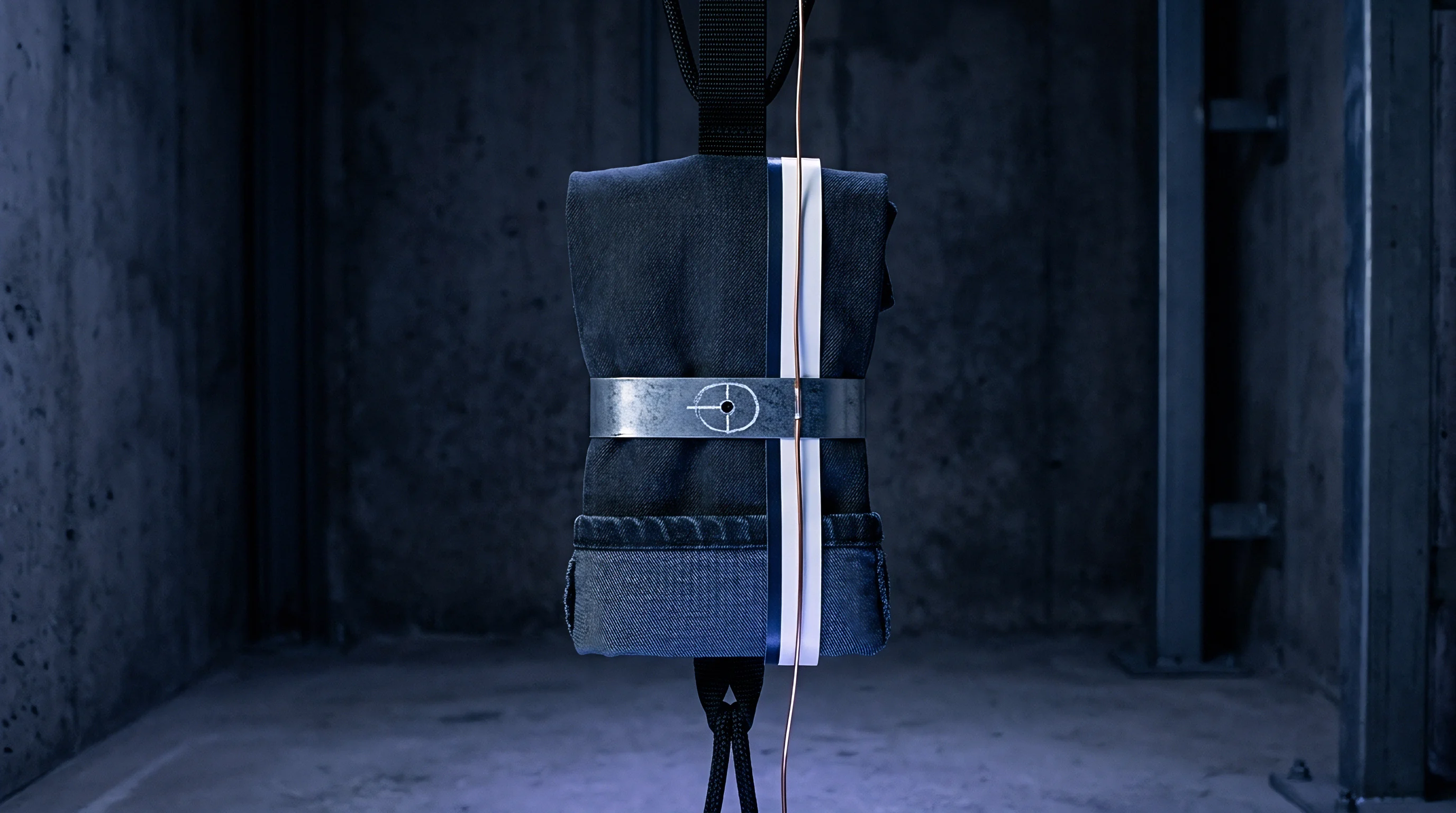
Pack Compression Foam Selection and Stack Expansion Allowances
Polyurethane and silicone compression foam selection requires balancing low initial pre-load against high-temperature expansion limits. Foams with steep stress-strain curves generate excessive mechanical reaction forces when cells undergo thermal expansion, accelerating separator pore collapse. Utilizing micro-cellular silicone foams with plateaued compression stress profiles limits maximum stack pressure spikes during thermal transients, keeping separator strain within safe structural boundaries.
Module mechanical design calculations must integrate cell thermal expansion coefficients, swelling rates, and separator viscoelastic compliance equations. Finite element macro-models of whole module stacks map individual layer elastic-plastic properties into structural shell and continuum elements. These pack-level simulations confirm that module structural tie-bars and end-plates maintain stack pressures within specified limits across all worst-case thermal transient scenarios.

Contractual Boundary Definition for Cell Strain Qualification
Defining clear compliance parameters in master supply agreements protects battery pack integrators from liabilities associated with separator structural degradation. Warranties must specify the precise mechanical pre-load range and thermal envelope within which the cell manufacturer guarantees separator structural integrity. If internal micro-shorting occurs within certified stack pressure and temperature boundaries, responsibility rests explicitly with the cell producer.
Writing these mechanical bounds into the cell specification sheet locks supplier accountability before committing capital to production tooling. Quality verification procedures mandate incoming lot testing using high-rate thermal-compression creep fixtures to confirm that delivered cell lots match finite element baseline performance curves.
How far can pack integration teams lower initial structural module pre-load to prevent transient thermal creep without introducing rapid mechanical fretting degradation under prolonged vehicular vibration exposure?