Melt Delivery Tube Geometry Influence on Atomization Vacuum Aspirator Pressure
Melt delivery tube setback and tip taper dictate atomization aspirator pressure, where sub-atmospheric suction prevents melt freeze-off and backpressure blowback.

Suction
High-velocity gas streams passing over a melt supply tip generate local sub-atmospheric static pressure zones. In close-coupled gas atomization systems, liquid metal relies on this static vacuum pressure to pull material continuously from the tundish into the primary disintegration zone. The static pressure measured at the tip exit plane is known as the aspirator pressure.
Negative aspirator pressure creates stable suction, drawing liquid metal into fine filaments. Positive aspirator pressure generates backpressure, driving gas up the liquid supply channel.
Fluid Dynamics of Close-Coupled Nozzles
Supersonic gas expansion across an annular gap drives momentum transfer at the liquid-gas boundary. As pressurized argon or nitrogen expands through a convergent-divergent nozzle manifold, kinetic energy peaks downstream of the nozzle throat. The gas stream accelerates past the boundary of the central delivery tube, creating a low-pressure wake zone.
The magnitude of this static vacuum depends on gas mass flow rate, stagnation pressure, and physical boundary shapes. Liquid metal exiting the delivery bore enters this localized low-pressure field, where aerodynamic shear forces overcome liquid metal surface tension and viscosity.
Operating gas pressures ranging from 1.5 MPa to 4.5 MPa produce static aspirator pressures between -5 kPa and -35 kPa under ideal nozzle alignments. When aspirator pressure shifts toward ambient or positive values, liquid stream delivery degrades rapidly. Flow field instabilities disrupt the primary atomization break-up length, yielding coarse droplets, satellite formation, and irregular particle size distributions.

Pressure Minima and Recirculation Structures
Gas flow detachment at the outer shoulder creates a toroidal low-density vortex behind the tube orifice. This recirculation zone anchors the vacuum field. The shape and location of the vortex dictate whether static suction remains constant or fluctuates during long production runs.
A well-defined recirculation vortex maintains continuous sub-atmospheric pressure across the entire orifice exit diameter.
Unstable vortices collapse periodically, causing pressure spikes that propagate into the liquid conduit. If local static pressure exceeds the hydrostatic head of the liquid metal column, gas bubbles enter the melt channel. Gas ingestion causes melt splashing, severe orifice erosion, and catastrophic liquid stream detachment.
Increasing gas supply pressure beyond the design limit forces shock structures upstream, collapsing the recirculation vortex and destroying static suction.
Fluctuations in aspirator vacuum directly affect melt flow rate stability. Liquid mass throughput scales with the differential pressure between the open tundish atmosphere and the atomization tip exit zone. Operational instability in aspirator pressure produces batch-to-batch variations in powder particle sizing, altering powder yields for powder metallurgy and additive manufacturing applications.
A persistent loss of vacuum aspirator pressure forces molten metal to pool on the delivery tip face, creating heavy skull buildup that eventually seals the gas orifice and terminates the atomization run entirely.


Tip
Setback protrusion relative to the gas nozzle throat plane governs the static pressure profile at the delivery interface. Small physical changes to the tube end profile alter how gas expands past the liquid outlet. Machined ceramic tips feature geometric parameters including protrusion length, chamfer taper angle, and face lip thickness.
Machining each dimension within tight tolerances maintains predictable aspirator pressure curves across varied gas manifold operating pressures.
Setback Distance and Axially Displaced Pressure Planes
Extending the ceramic body forward into the high-speed jet alters local expansion shock waves. Setback distance defines the axial location of the tip exit relative to the narrowest cross-section of the surrounding gas ring. Positive setback positions the tip downstream of the gas throat plane.
Negative setback recessed positions retract the tip inside the manifold housing.
Placing the tip exactly in the low-pressure core of the expanding gas jet optimizes aspirator vacuum. Retracting the tube too far inside the gas nozzle shell isolates the orifice from the primary high-velocity shear zone, resulting in weak aspirator suction. Extending the tube too far forward positions the orifice in a zone of expanding gas shocks, where static pressure rises back toward atmospheric levels.
| Setback Distance (mm) | Chamfer Angle (deg) | Gas Pressure (MPa) | Aspirator Vacuum (kPa) | Flow Field State |
|---|---|---|---|---|
| -1.00 | 15.0 | 2.5 | -4.2 | Weak Suction / Pulsing |
| -0.50 | 15.0 | 2.5 | -12.8 | Stable Atomization |
| 0.00 | 15.0 | 2.5 | -22.5 | Optimal Vacuum Peak |
| 0.50 | 15.0 | 2.5 | -18.1 | Stable Atomization |
| 1.00 | 15.0 | 2.5 | -6.5 | Shock Interference Zone |
| 0.00 | 30.0 | 2.5 | -15.3 | Increased Recirculation Drag |
| 0.00 | 45.0 | 2.5 | +2.1 | Overpressure Blowback Risk |

Chamfer Angle and Annular Lip Thickness
External cone geometry modifies the boundary layer separation point along the delivery exterior. Steeper external chamfer angles force expanding gas streams to turn sharply around the tip shoulder. Small chamfer angles between 15 degrees and 25 degrees allow smooth supersonic gas flow parallel to the central delivery axis, stabilizing the boundary layer and minimizing unwanted turbulent drag.
When chamfer angles exceed 35 degrees, gas flow detachment occurs prematurely, producing turbulent vortex shedding. This instability shifts the static pressure profile and reduces net aspirator vacuum strength.
Annular lip thickness refers to the flat land area surrounding the central melt exit bore. A broad flat face provides space for recirculation vortices to detach and reattach unpredictably. Thin annular lips below 0.50 mm minimize face area, preventing melt buildup and stabilizing local aspirator suction values during prolonged metal pouring.
Extending the melt delivery tip beyond the gas expansion focal point moves the liquid exit into positive static pressure shock structures.
Delivering consistent gas flow momentum over the tip shoulder requires smooth transitions between external Chamfer surfaces and the flat nose face.

Orifice
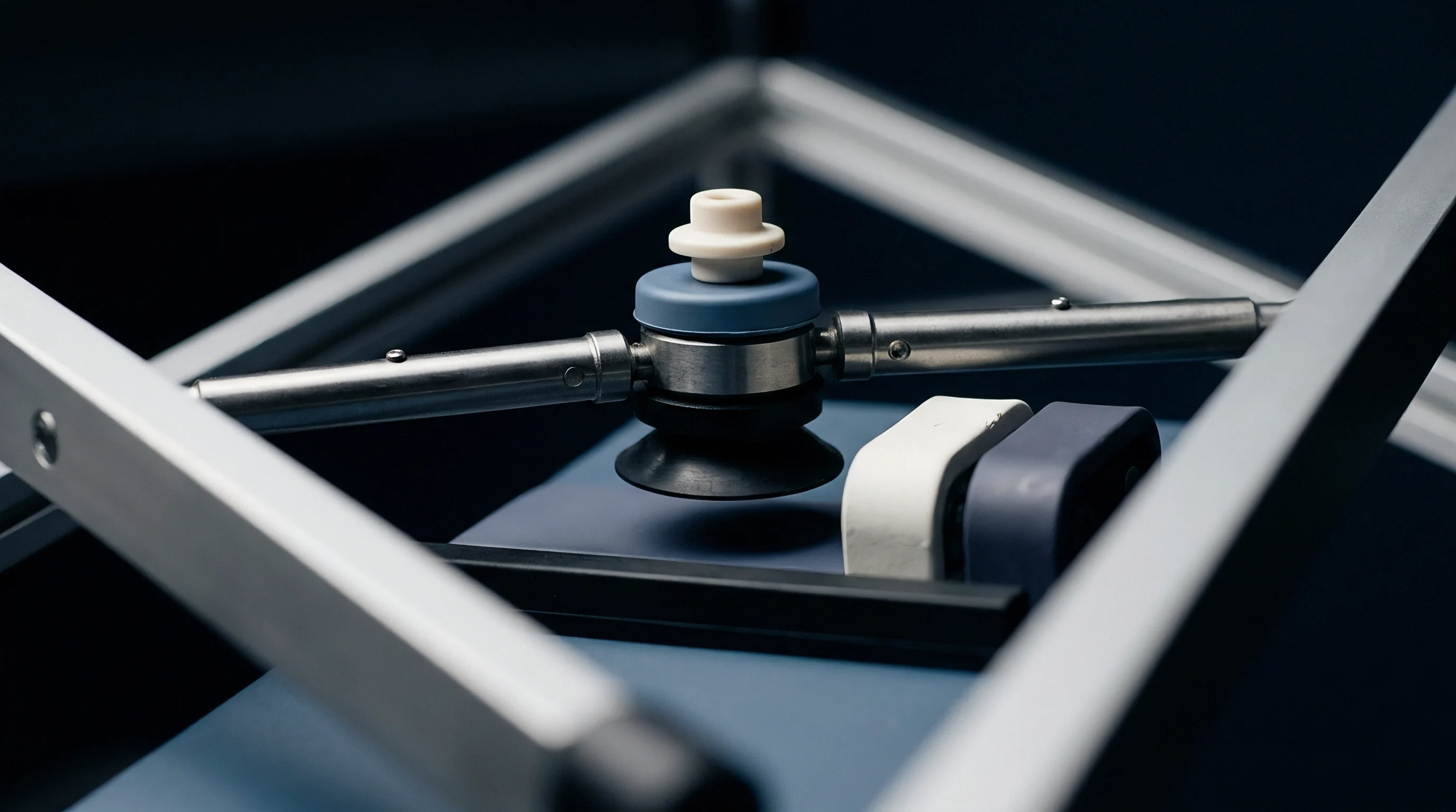
Internal bore dimensions determine liquid metal velocity, head pressure drop, and volumetric throughput during active atomization runs. Channel geometry acts as a fluid metering restraint. While external nozzle geometry shapes the supersonic gas field, the internal channel establishes hydraulic resistance against aspirator suction forces pulling metal down from the tundish.
Internal Diameter Scaling and Friction Losses
Liquid metal viscosity and wall contact forces establish capillary resistance within the central passage. Expanding the internal bore diameter increases liquid flow volume exponentially according to Poiseuille flow relationships, assuming constant head height and fixed aspirator vacuum levels.
A narrow internal bore diameter increases fluid wall friction, demanding stronger negative aspirator pressure to maintain uniform melt discharge rates. Conversely, a large internal bore reduces fluid friction, allowing high mass flow rates. If mass flow rate increases beyond the shear capability of the supersonic gas jet, atomization efficiency drops sharply, increasing the average particle size of the finished metal powder.
- Capillary Resistance Control ~ Internal bore diameter precision within +/- 0.03 mm fixes liquid mass delivery rates and prevents aspirator pressure starvation.
- Exit Chamfer Geometry ~ A slight internal relief chamfer at the bore exit prevents liquid metal edge pinning and smooths filament detachment into the gas jet.
- Channel Wall Finish ~ Surface roughness below 1.6 micrometers Ra minimizes wall friction losses, sustaining high fluid momentum at low aspirator vacuum levels.
- Thermal Bore Expansion ~ Refractory thermal growth during liquid metal contact reduces net internal cross-sectional area by up to 1.5 percent at 1650 degrees Celsius.

Refractory Material Selection and Erosion Profiles
High-temperature molten alloys induce chemical attack and mechanical wash out inside ceramic delivery channels. Boron nitride, dense alumina, and zirconia-stabilized ceramics serve as standard refractory substrates. Material choice alters wear dynamics over time, directly influencing long-term aspirator pressure balance.
Machined boron nitride components provide low wetability against molten steels and nickel superalloys, preserving clean orifice exit geometry. However, high-velocity gas flows carrying fine metal spatters gradually erode soft ceramic grades. Erosion expands the internal bore diameter while rounding the outer chamfer edge during multi-hour production cycles.
As the outer tip lip erodes from a sharp shoulder to a rounded profile, the gas flow separation point moves upstream. This geometric drift reduces aspirator vacuum magnitude, shifting process pressure toward zero and increasing the risk of freeze-off events.
Although minor dimensional erosion on internal exit chamfers is sometimes assumed to have negligible effect on vacuum stability at constant gas inlet pressure, geometric shifts still degrade suction performance over extended runs.


Alignment
Concentric placement between the liquid feed channel and the surrounding gas manifold prevents asymmetric suction distribution. Centering errors disrupt the uniform annular clearance gap between the gas nozzle inner wall and the tube outer chamfer. Precise concentric alignment maintains equal gas momentum across all circumferential sectors of the atomization zone.
Radial Offset and Asymmetric Static Pressure Distribution
Lateral displacement of 0.10 mm generates unbalanced static suction forces across opposite exit quadrants. The narrow gap side experiences higher local gas velocities and deeper aspirator vacuum levels. The wide gap side receives lower gas velocity, resulting in reduced vacuum or localized positive backpressure pockets.
Unequal static pressure forces liquid metal to bend toward the high-vacuum sector upon exiting the orifice. Liquid stream deflection causes melt droplets to impact the inner gas manifold wall, creating aggressive skull growth. Metallic accretions on the manifold face alter gas flow symmetry further, causing rapid decay of aspirator vacuum performance across the entire atomization chamber.
| Concentricity Offset (mm) | Quadrant 1 Vacuum (kPa) | Quadrant 2 Vacuum (kPa) | Quadrant 3 Vacuum (kPa) | Quadrant 4 Vacuum (kPa) | Stream Streamline State |
|---|---|---|---|---|---|
| 0.00 | -18.5 | -18.4 | -18.5 | -18.5 | Concentric Liquid Core |
| 0.05 | -21.0 | -18.2 | -15.5 | -18.3 | Minor Stream Inclination |
| 0.10 | -24.5 | -17.8 | -11.2 | -17.9 | Severe Deflection / Wall Impact |
| 0.20 | -29.0 | -16.1 | +1.5 | -16.4 | Localized Backpressure Blowback |
Thermal Expansion Mismatches and Mounting Drift
Differential thermal growth between metallic housings and ceramic inserts shifts exit positioning during operation. Stainless steel or copper gas manifolds expand significantly under thermal loads, whereas refractory boron nitride exhibits minimal thermal expansion. Rigid clamping systems without compliance features cause component tilting under operational thermal cycles.
Angular tilt misalignments greater than 0.5 degrees relative to the central gas jet axis ruin the symmetrical suction field. Tilt causes the tip face to sit unevenly in the axial shock pattern, exposing one side of the orifice exit plane to supersonic expansion while the opposite side sits in a subsonic compression wave.
Concentricity offset between the liquid channel and gas manifold exceeding 0.05 mm causes asymmetric suction forces that deflect liquid metal streams into the gas nozzle wall.
To audit delivery assembly alignment on production atomization lines, technicians execute formal inspection routines before heating the tundish system:
- Mount the refractory delivery tube into the central alignment holder using calibrated torque limits on retaining bolts.
- Install an optical laser centering gauge into the liquid supply channel bore to measure axial deviation along the assembly centerline.
- Adjust lateral positioning screws on the gas manifold base until total radial runout reads below 0.02 mm on dial indicators.
- Verify concentric clearance gaps around the entire annular exit perimeter using feeler gauges or optical shadowgraph sensors.
- Lock mechanical alignment collars and re-verify concentricity after thermal preheating of the delivery assembly to 1000 degrees Celsius.
Procurement documents must mandate that delivery tube concentricity between the inner bore axis and outer chamfer locating surfaces stays within 0.03 mm total indicator reading to preserve vendor performance warranties.

Calibration
Gas supply inlet pressure maps directly to static aspiration suction over operational delivery tube lifetimes. Operating engineers construct calibration curves to match gas manifold stagnation pressure with the specific delivery tube geometry installed. Establishing these baseline relationships enables real-time detection of geometric wear or alignment drift during active melt atomization runs.

Gas Supply Pressure Response Curves
Inlet gas feed adjustments alter downstream expansion wave structures and tip pressure readings. Raising gas inlet pressure increases gas mass flow and jet velocity, deepening the aspirator vacuum until reaching a maximum suction threshold. Beyond this critical pressure threshold, shock diamonds shift downstream of the tip face, causing aspirator vacuum to plateau or decrease rapidly.
Operating above the peak suction pressure point consumes excess inert gas without improving liquid disintegration performance, as gas consumption scales directly with pressure. Operational calibration identifies the precise gas inlet pressure window where aspirator vacuum remains stable against minor gas supply variations.
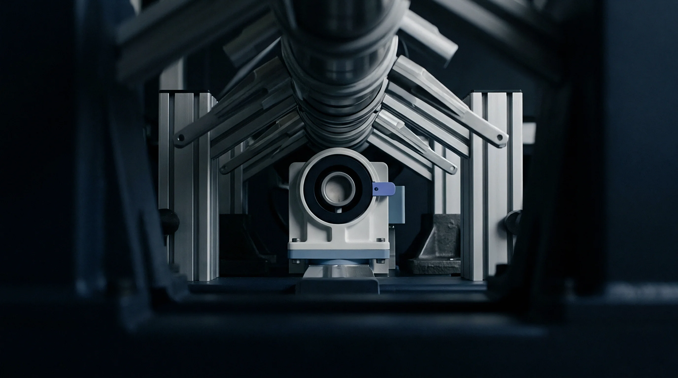
Worked Static Suction Calculations under Variable Setback
Consider an atomization system running liquid metal through a boron nitride feed tube at 1650 degrees Celsius using argon gas. The gas manifold features an annular exit gap of 1.20 mm surrounding a tube tip with an outer diameter of 10.00 mm and an inner bore diameter of 3.00 mm. Operating assumptions set argon inlet supply pressure at 2.80 MPa, gas temperature at 293 Kelvin, and liquid metal head height in the tundish at 250 mm (liquid density 7000 kg/m³).
Hydrostatic head pressure of the liquid metal column at the orifice inlet equals:
P_hydrostatic = density gravity height = 7000 9.81 0.250 = 17,167 Pa = +17.17 kPa
To maintain liquid flow without gas blowback or pressure-driven stream surging, net pressure at the orifice exit must remain negative relative to liquid head driver forces. Baseline cold calibration with zero setback (tip flush with gas throat plane) yields a measured aspirator vacuum of -22.50 kPa. Net driving differential pressure pushing liquid metal through the delivery channel calculates as:
P_net = P_hydrostatic – P_aspirator = +17.17 kPa – (-22.50 kPa) = +39.67 kPa
Now assume thermal growth and mechanical tolerance stack-up shift the tip setback forward by +0.80 mm during operation. Calibration tables indicate that a +0.80 mm setback reduces aspirator vacuum magnitude to -8.20 kPa due to shock wave position displacement. Re-calculating net driving differential pressure gives:
P_net = +17.17 kPa – (-8.20 kPa) = +25.37 kPa
This 36 percent drop in net driving pressure reduces liquid mass flow rate from 4.80 kg/min down to 3.06 kg/min. The Gas-to-Melt Ratio (GMR) shifts from an intended target of 2.10 up to 3.29, increasing argon gas consumption per kilogram of atomized metal powder by 56 percent.
If mechanical drift shifts setback further to +1.20 mm, aspirator pressure turns positive to +3.50 kPa. Net driving pressure drops below liquid head requirements, and positive backpressure forces gas bubbles into the melt tube, triggering melt freeze-off or liquid blowback out of the open tundish top.
How do real-time changes in molten alloy surface tension and viscosity interact with high-frequency aspirator pressure oscillations when operating close to maximum aspirator suction limits?

Contract
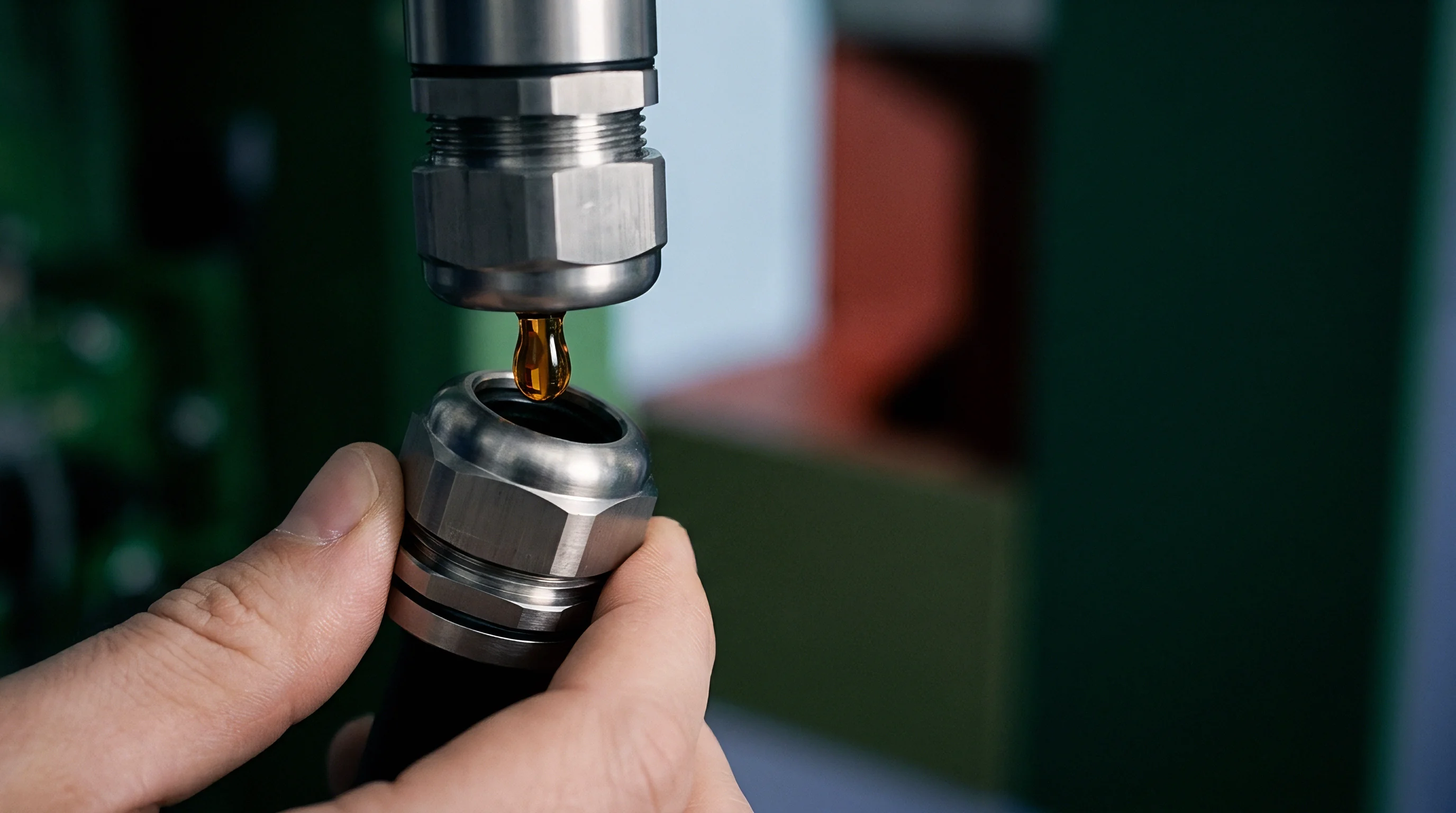
Purchasing specifications for high-purity ceramic feed nozzles require explicit dimensional tolerances and surface roughness limits. Standard procurement terms often neglect geometric interface details, focusing solely on refractory chemical purity or density metrics. Incorporating precise geometric control clauses into supply agreements protects powder manufacturing operations from subtle component variations that destabilize aspirator pressure.
Tolerance Specifications and First-Article Inspection
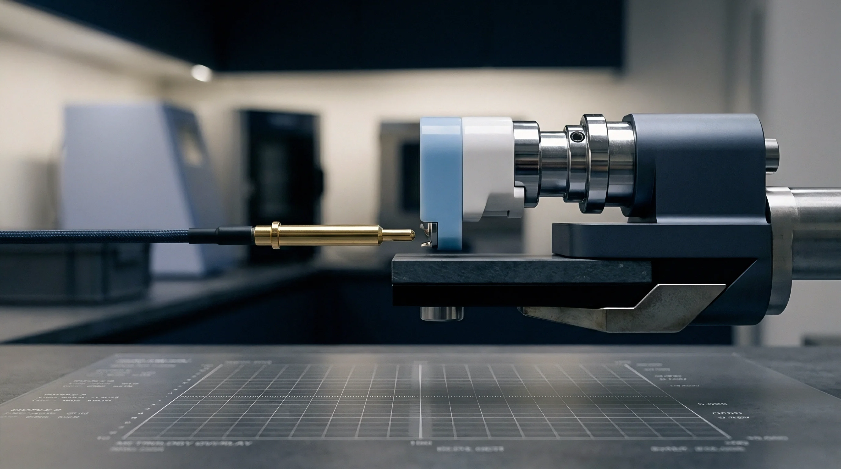
Receiving procedures for ceramic components combine coordinate measuring machine verification with optical profile scanning. Ceramic manufacturing processes like cold isostatic pressing followed by sintering yield dimensional shrinkage variations up to 2 percent if post-sintering finish machining is omitted. Sintered unmachined ceramic nozzles fail to hold the tight setback and concentricity tolerances required for stable aspirator suction.
Component drawings must specify diamond-ground finishes on all critical external chamfers, locating shoulders, and internal bore channels to prevent liquid blowback. Standard drawing notes must enforce tight geometric limits:
- Bore Concentricity Standard ~ Total indicator reading between central liquid channel and external positioning datum surfaces must not exceed 0.025 mm.
- Chamfer Angle Tolerance ~ External taper cone angle must remain within +/- 0.25 degrees of specified design values along the entire shoulder length.
- Tip Flat Squareness ~ Exit face flat surface squareness relative to the central bore axis must hold within 0.015 mm per millimeter of outer diameter.
- Surface Finish Requirement ~ Ground ceramic surfaces on gas-contact chamfers must achieve a surface finish of Ra 0.4 micrometers or smoother.

Amortization and Total Cost of Ownership Seams
Refractory wear rates dictate consumable tooling expenses per metric ton of atomized metal powder output. High-precision diamond-ground boron nitride nozzles carry up to three times the initial unit purchase cost of standard unground ceramic tubes. However, unground components induce yield losses through unstable aspirator pressure, causing frequent batch aborts and wider powder particle size distributions.
Scrap costs from off-spec powder sizing easily outweigh initial tooling savings achieved by buying low-precision ceramic nozzles. Amortizing precision-machined refractory nozzles over large powder production volumes demonstrates that tight geometric control lowers total operating expenses per kilogram of qualified powder delivered.
Clear warranty boundaries place compliance ownership on the ceramic component supplier to verify dimensional drawing tolerances prior to shipment, while the atomization plant owns line mounting alignment discipline and operational gas supply calibration.