Lithium Cell Chemistry Stress Resistance under Mechanical Pressure Protocols
Optimal mechanical constraint extends lithium cell cycle life by suppressing electrode delamination while avoiding separator pore collapse and intergranular cathode fracture

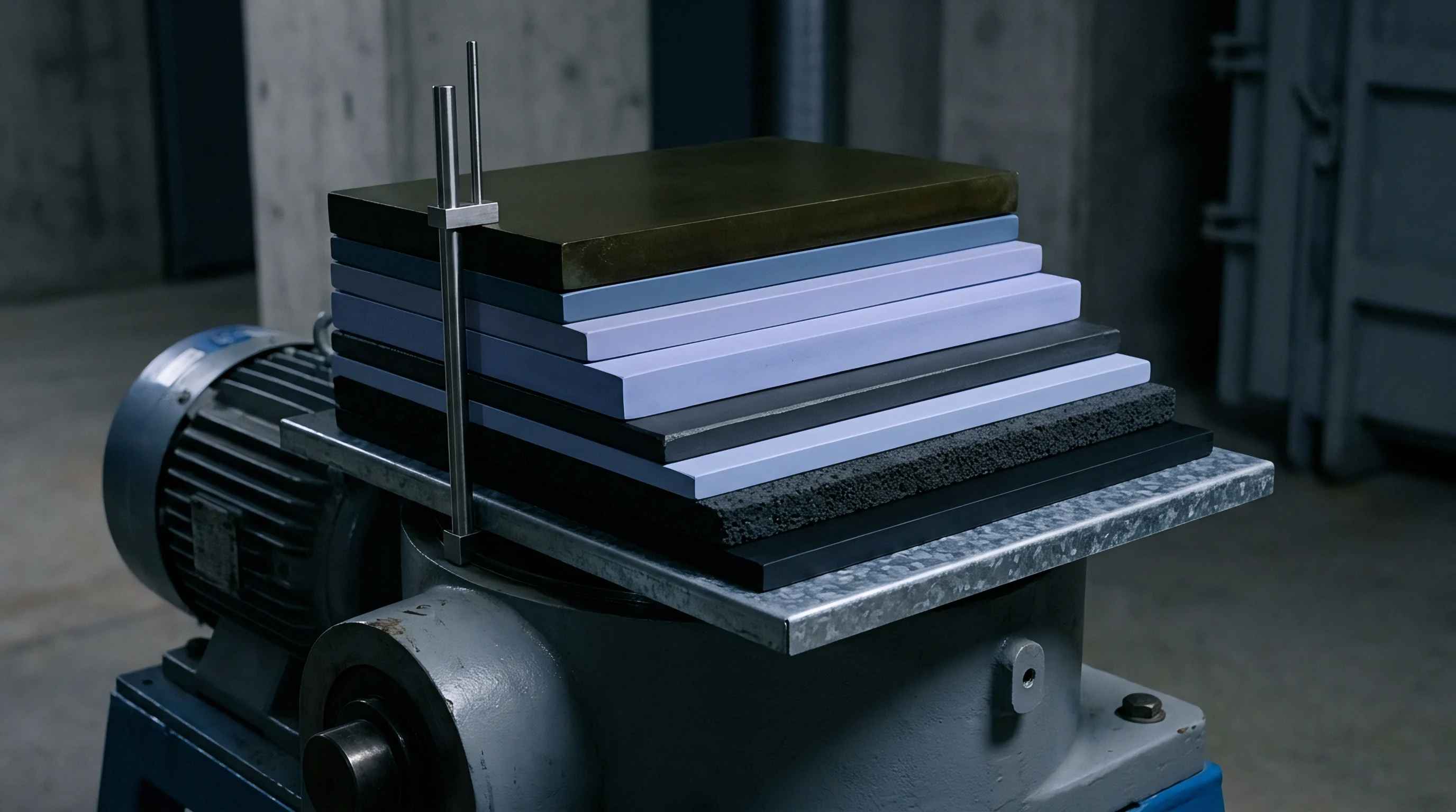
Mechanics
Clamping a cell alters how liquid electrolyte migrates through the porous electrode matrix during formation and initial cycling. As intercalation proceeds, active materials expand: graphite anodes swell by eight to twelve percent at full state of charge as inter-planar spacing widens, while silicon-composite anodes can expand beyond three hundred percent depending on mass fraction. Cycling a pouch or prismatic format without mechanical constraint allows this breathing to delaminate active coatings from current collectors, driving up impedance and capacity loss.
External stack pressure preserves interfacial contact, though excessive force expels electrolyte from separator pores and starves the core.
Cell geometry governs internal stress distribution. Prismatic designs in aluminum cans direct expansion against flat sidewalls, concentrating pressure along the central vertical axis. Pouch cells lack rigid walls, requiring module plates inside the pack to maintain compression.
Cylindrical formats convert radial swelling into hoop stress against nickel-plated steel cans, maintaining outer dimensions while building internal hydrostatic pressure. Chemical tolerance to these mechanical loads depends on crystal structure, binder shear strength, and separator stability at operating temperatures.
High-nickel layered cathodes like NMC 811 and NCA undergo anisotropic lattice contraction along the c-axis during deep delithiation, generating intense local stress across polycrystalline particles. When high stack pressure reinforces this internal strain, primary crystallites fracture along grain boundaries, exposing fresh transition metal surfaces that accelerate electrolyte decomposition, gas production, and metal dissolution. Lithium iron phosphate (LFP) exhibits a much smaller volume change ~ roughly two to three percent ~ between FePO4 and LiFePO4 phases, tolerating higher static loads without severe particle cracking, though flexible binder networks still face strain under uneven pressure fields.
Pouch cells utilizing high-silicon anodes demonstrate a tripling of internal peak forces beyond three hundred cycles when constrained by rigid unyielding endplates.
Required clamping force evolves over operational life. Factory formation needs baseline pressure between zero point one and zero point three megapascals to prevent gas pockets from isolating dry spots during initial solid electrolyte interphase (SEI) growth. As SEI buildup, dead lithium, and particle debris accumulate, irreversible swelling increases.
A fixed-gap constraint exerting zero point three megapascals at cycle ten can climb past two point five megapascals by cycle one thousand, forcing liquid electrolyte outward toward pouch folds or header voids and leaving dry regions at the electrode core where current density spikes.

Volume Variance across Active Cathode and Anode Matrices
Thermodynamic phase changes within active particles govern bulk dimensional shifts. In graphitic carbon, lithium staging from stage four to stage one (LiC6) causes stepwise jumps in interlayer spacing that pulse mechanical stress into adjacent binder networks. Silicon nanoparticles amplify this volume swing significantly, expanding up to three hundred percent when fully lithiated to Li15Si4 at room temperature.
Without elastic binders like polyacrylic acid (PAA) and controlled external constraint, expanding silicon pulverizes conductive carbon matrices and detaches from current collectors in fewer than fifty cycles.
Cathode microstructure determines yield limits under mechanical load. Standard polycrystalline NMC 811 particles, formed via co-precipitation, contain hundreds of primary crystallites fused at random grain boundaries. Compression concentrates force at point contacts, generating localized Hertzian stresses that exceed interfacial yield strength and open micro-fissures to electrolyte infiltration.
Single-crystal NMC eliminates these internal boundaries, providing sufficient shear resistance to endure stack pressures up to two megapascals without intra-granular fracture.
Solid-state designs impose far tighter mechanical requirements because solid polymer or sulfide ceramic electrolytes lack fluid mobility to bridge gaps. Sulfides require continuous stack pressures between five and fifteen megapascals to preserve interfacial contact and close voids formed during lithium stripping. If pressure drops below five megapascals, interfacial voiding concentrates local current flux, driving dendrites through ceramic separators during subsequent plating cycles.

Pressure Distribution Profiles in Pouch versus Prismatic Enclosures
Pressure uniformity across pouch cells depends directly on module endplate rigidity and foam compliance. Aluminum-laminate casings readily deform under local pressure gradients; dropping constraint below fifty kilopascals permits gas accumulation and pouch pillowing during charge. Non-uniform compression creates mismatched current distributions, as over-compressed zones suffer restricted electrolyte permeability and higher ionic impedance, shifting current into lower-pressure regions to form thermal hotspots and uneven state-of-charge profiles across the electrode area.
Prismatic aluminum cans provide containment but generate complex internal stress gradients. Can walls ~ typically zero point eight to one point two millimeters thick to conserve weight ~ bow outward under internal gas or swelling forces, displacing most at the face centroid. This flexing relieves compression at the center of the jellyroll while creating pinch points along the casing corner radii, where elevated shear accelerates separator wear and increases short-circuit risk.
Cylindrical cells accommodate expansion through internal void space and radial stress conversion. Standard 18650, 21700, and 4680 designs incorporate a central core or hollow mandrel that allows inward expansion. The rigid steel can withstands radial pressures above three megapascals before measurable outer expansion occurs, though severe swelling can buckle inner wraps inward and shear current collector foils at tab welds while constricting separator pore networks.

Separator Creep and Pore Closure under Sustained Load
Separator microstructure limits permissible static loads. Polyolefin membranes manufactured by wet or dry stretching feature ultra-high molecular weight polyethylene (UHMWPE) or polypropylene (PP) fibril networks with thirty-five to fifty-five percent porosity. Sustained static loads above zero point eight megapascals at elevated temperatures induce polymer creep, collapsing average pore diameters from forty nanometers down to under ten nanometers, which impedes ion transport and elevates bulk Ohmic resistance.
Ceramic coatings improve separator puncture resistance and thermal stability. Alumina (Al2O3) or silica (SiO2) layers create a rigid porous skeleton that spreads mechanical loads and shields the polymer substrate from pore collapse. Under cyclic compression, however, brittle ceramic layers can shed sub-micron particles that lodge in the separator matrix or embed into metallic lithium, concentrating local stress and risking membrane puncture under dynamic shock.
| Chemistry Type | Cell Format | Volumetric Swelling Range (%) | Optimal Static Pressure (MPa) | Separator Compression Threshold (MPa) |
|---|---|---|---|---|
| NMC 811 / Graphite | Pouch | 6.0 – 9.0 | 0.30 – 0.60 | 1.20 |
| NMC 811 / Silicon-Graphite (10% Si) | Pouch | 14.0 – 22.0 | 0.50 – 1.00 | 1.50 |
| LFP / Graphite | Prismatic | 2.0 – 4.5 | 0.20 – 0.50 | 2.00 |
| LFP / Graphite | Blade / Long Prismatic | 3.0 – 5.5 | 0.30 – 0.70 | 1.80 |
| Sulfide Solid-State / Li-Metal | Pouch | 10.0 – 30.0 (interfacial) | 5.00 – 15.00 | 25.00 (Solid Ceramic) |
Compression thresholds must account for the full operating temperature window. Low temperatures stiffen polymer separators and binders, reducing elastic recovery, while temperatures around fifty degrees Celsius soften polyolefin membranes and lower the threshold for pore collapse under load. A cell that functions stably under zero point five megapascals at twenty-five degrees Celsius may experience separator compaction and localized shorting under that same load in warmer conditions.
Tracking mechanical behavior requires monitoring state of charge, clamping load, and impedance concurrently. In electrochemical impedance spectroscopy (EIS), high-frequency Ohmic resistance (R0) and charge transfer resistance (Rct) respond distinctly to pressure changes: rising R0 indicates electrolyte depletion or separator pore constriction, whereas spikes in Rct signal active material isolation or binder failure.
Whether non-uniform surface pressure below zero point two megapascals accelerates lithium plating faster than uniform over-compression at one point five megapascals remains contested across high-rate cycling regimes.


Strain
Graphite lattice expansion during lithiation generates local shear stress across binder networks. Intercalation forces graphene planes to slide and separate, transferring strain into polyvinylidene fluoride (PVDF) or styrene-butadiene rubber (SBR) binders. Over hundreds of cycles, this mechanical cycling weakens binder adhesion and forms micro-voids between conductive carbon additives and active anode grains, breaking electronic percolation networks and causing irreversible capacity loss.
The solid electrolyte interphase (SEI) undergoes continuous strain during active material expansion. Composed of brittle inorganic species like lithium fluoride and lithium carbonate alongside organic components, the SEI has an elastic elongation limit below five percent. Particle expansion beyond this threshold fractures the film, exposing bare anode surfaces and consuming both lithium and solvent to regenerate passivation layers.
This continuous crack-and-heal cycle thickens the interphase, depletes available electrolyte, and elevates cell polarization.
Excessive compression exacerbates interfacial breakdown by preventing binder relaxation. Rigid module endplates trap binder chains in high-stress states, speeding viscoelastic stress relaxation and chain scission. As elasticity degrades, the binder cannot pull contracting anode particles back into contact during discharge, leaving isolated particles as unreactive dead mass within the electrode.

Microstructural Fracture Dynamics in High-Nickel Cathodes
Polycrystalline high-nickel cathodes experience severe intergranular stress during deep cycling. In NMC 811, extracting over seventy percent of lithium induces anisotropic lattice strain: the a- and b-axes contract smoothly while the c-axis undergoes rapid collapse at high SOC. This crystallographic mismatch sets up internal shear along crystallite boundaries.
Under high stack compression, these internal stresses combine with external load to exceed fracture limits, opening intergranular fissures.
Intergranular cracking accelerates coupled chemical degradation. Capillary forces draw liquid electrolyte into grain boundaries, where trace hydrofluoric acid (HF) from LiPF6 hydrolysis dissolves manganese, cobalt, and nickel. Dissolved transition metal ions migrate across the separator and deposit onto the anode, where they catalyze SEI breakdown and accelerate capacity fade.
Single-crystal cathodes remove grain boundaries entirely, yielding higher resistance to mechanical fracture. Synthesizing micron-scale single crystals prevents intra-granular shear planes during high-voltage delithiation. Under matched constraint, single-crystal NMC 811 exhibits less than one-fifth the particle damage of polycrystalline material after one thousand deep cycles, permitting higher static clamping pressures without inducing cathode breakdown.

Solid Electrolyte Interphase Rupture under Repeated Constraint Shifts
Dynamic loads from road vibration, vehicle acceleration, and thermal cycling apply fluctuating stress fields across cell assemblies. Unlike static clamping, dynamic strain fatigues the adhesive bond between organic SEI components and the anode substrate. Under severe dynamic cycling, large SEI flakes delaminate, exposing bare anode surfaces to direct solvent attack.
In silicon-graphite blends, dynamic SEI fracture drives degradation. Because silicon particles expand by tens of percent each cycle, the local strain rate outpaces viscoelastic relaxation within the SEI film. The passivation layer fractures under tension during charging and buckles during delithiation, continuously consuming active lithium to rebuild the interphase and accelerating capacity fade.
Adaptive mechanical constraint helps stabilize these interfaces. Employing elastomeric compression pads or active clamping systems to maintain constant force rather than fixed displacement keeps interfacial stress within acceptable boundaries. Constant-force setups direct expanding particles into accessible inter-particle pore volume, mitigating tensile strain across the passivation film.

Local Stress Gradients as Catalysts for Lithium Dendrite Growth
Pressure variations create localized stress gradients across the electrode-separator boundary. In low-pressure regions where contact is lost, electrolyte pools and ion transport resistance drops, causing current density to spike along the perimeter during fast charging. This concentrated current flux, combined with poor interfacial contact, forces metallic lithium to plate on the anode surface rather than intercalate into graphite.
Conversely, localized over-compression creates pinch points in the separator. High pressure compacts polymer fibrils, choking pore channels and increasing local ionic impedance. Lithium ions divert around these restricted zones, concentrating current density along the boundary of the pressure peak.
Lithium dendrites nucleate at these high-flux rings, propagating across the separator surface and through micro-defects until causing internal short circuits.
The structural characteristics of these mechanical degradation mechanisms are summarized below:
- Intergranular Cathode Cracking occurs in polycrystalline high-nickel oxides when anisotropic lattice collapse under high SOC combines with external mechanical shear, exposing primary grain boundaries to electrolyte HF attack.
- SEI Mechanical Delamination results from cyclic volumetric strain exceeding the five percent elongation limit of inorganic passivation compounds, driving continuous lithium consumption.
- Localized Lithium Plating initiates at boundaries of pressure gradients where ionic impedance mismatches force current density spikes during rapid lithiation cycles.
- Separator Pore Collapsing develops under sustained static pressure exceeding one point two megapascals at elevated pack temperatures, driving up bulk Ohmic resistance through ionic path restriction.
- Current Collector Tab Shear emerges from differential lateral expansion between the electrode stack and fixed metallic tabs during repeated thermal and mechanical swelling loops.
| Degradation Mode | Mechanical Root Cause | Physical Manifestation | Electrochemical Diagnostic Signal |
|---|---|---|---|
| Particle Pulverization | High Hertzian point contact stress | Active material grain fracture | Rapid capacity fade, loss of active material (LAM) |
| SEI Continuous Thickening | Cyclic expansion breaking surface film | Thick organic-inorganic crust buildup | Loss of lithium inventory (LLI), rising Rct |
| Lithium Metal Plating | Pressure gradient induced current focusing | Dendritic metallic lithium accumulation | Shift in differential capacity (dQ/dV) peaks, self-discharge |
| Separator Creep Shear | Over-compression under thermal load | Polymer fibril compaction and thin spots | Sharp drop in R0 resistance prior to soft shorting |
| Tab Fatigue Cracking | Unconstrained lateral electrode motion | Metal tab micro-fractures at weld seams | Intermittent open-circuit voltage spikes, localized heating |
Managing cell strain requires balancing interfacial contact against the mechanical thresholds of separators, active materials, and polymer binders. Exceeding these limits shortens cycle life and elevates the risk of short circuits.
Elastic compression pads ought to yield at the precise rate of composite anode growth to protect fragile separator pore channels.


Fixture
Mechanical characterization requires load fixtures capable of isolating mechanical variables from thermal and electrical interference. Standard test channels integrate precision servo-hydraulic or electromechanical actuators with rigid load frames inside multi-channel environmental chambers. During cycling, the bench applies defined static pre-loads or dynamic displacements while recording force, platen travel, cell voltage, and impedance spectra.
Tactile pressure mapping arrays placed within test fixtures provide spatial resolution of stress distributions across cell faces. Thin piezoresistive or capacitive sensor sheets capture local pressure gradients down to zero point five millimeter resolution, revealing internal thickness variations, gas buildup, and edge-effect stress concentrations that single-point load cells miss.
Testing encompasses static compression, cyclic fatigue, and abuse evaluation. Standards including UN 38.3, UL 1642, IEC 62133-2, and SAE J2464 define impact, crush, vibration, and mechanical shock criteria required to prevent thermal runaway, fire, or enclosure rupture. Automotive and grid-storage qualification programs extend beyond these baselines, mandating thousands of constrained cycles under application-specific load profiles.
UN Manual of Tests and Criteria Section 38.3.4.6 demands continuous physical tracking of cell voltage for six hours post-impact to confirm structural isolation of internal elements.

Static Load Frames and Dynamic Pressure Mapping Instrumentation
Static test frames require high structural rigidity to prevent fixture compliance from masking cell expansion. Frames designed for extended cycling incorporate ground steel tie-rods and rigid platens instrumented with temperature-compensated strain gauge bridges. Platen surfaces are ground flat within five micrometers to ensure measured pressure non-uniformities originate strictly from internal cell dynamics.
Dynamic pressure mapping demands careful calibration across temperature extremes. Tactile piezoresistive arrays drift when exposed to temperatures between minus thirty and plus sixty degrees Celsius, requiring thermal insulation barriers or active software compensation. Synchronizing matrix pressure data with high-speed imaging and multi-channel EIS links localized stress spikes directly to specific electrochemical phase transitions.
The following step-by-step procedure outlines the standard mechanical stress characterization protocol conducted on test channel fixtures:
- Mount the fully conditioned test cell between ground platen surfaces featuring an inline piezoresistive pressure mapping array and high-resolution load cell.
- Apply the baseline static pre-load force corresponding to zero point three megapascals at fifty percent state of charge and room temperature.
- Lock the fixture platen positions to establish a constant-volume constraint baseline, or engage servo-control to maintain a constant-force regime depending on test objectives.
- Transfer the entire load fixture into an environmental chamber and stabilize the assembly at the target test temperature for four hours.
- Execute five baseline C/10 charge-discharge cycles while recording force development, dimensional deflection, surface temperature profiles, and multi-frequency EIS spectra at ten percent SOC intervals.
- Initiate accelerated dynamic cycling protocols at prescribed C-rates while continuously monitoring localized pressure peak distributions across the matrix array.
- Pause cycling every one hundred loops to perform differential capacity analysis (dQ/dV) under relaxed static conditions to quantify active material loss versus mechanical strain accumulation.

How Do Crush Test Speeds Alter Internal Short Circuit Modes?
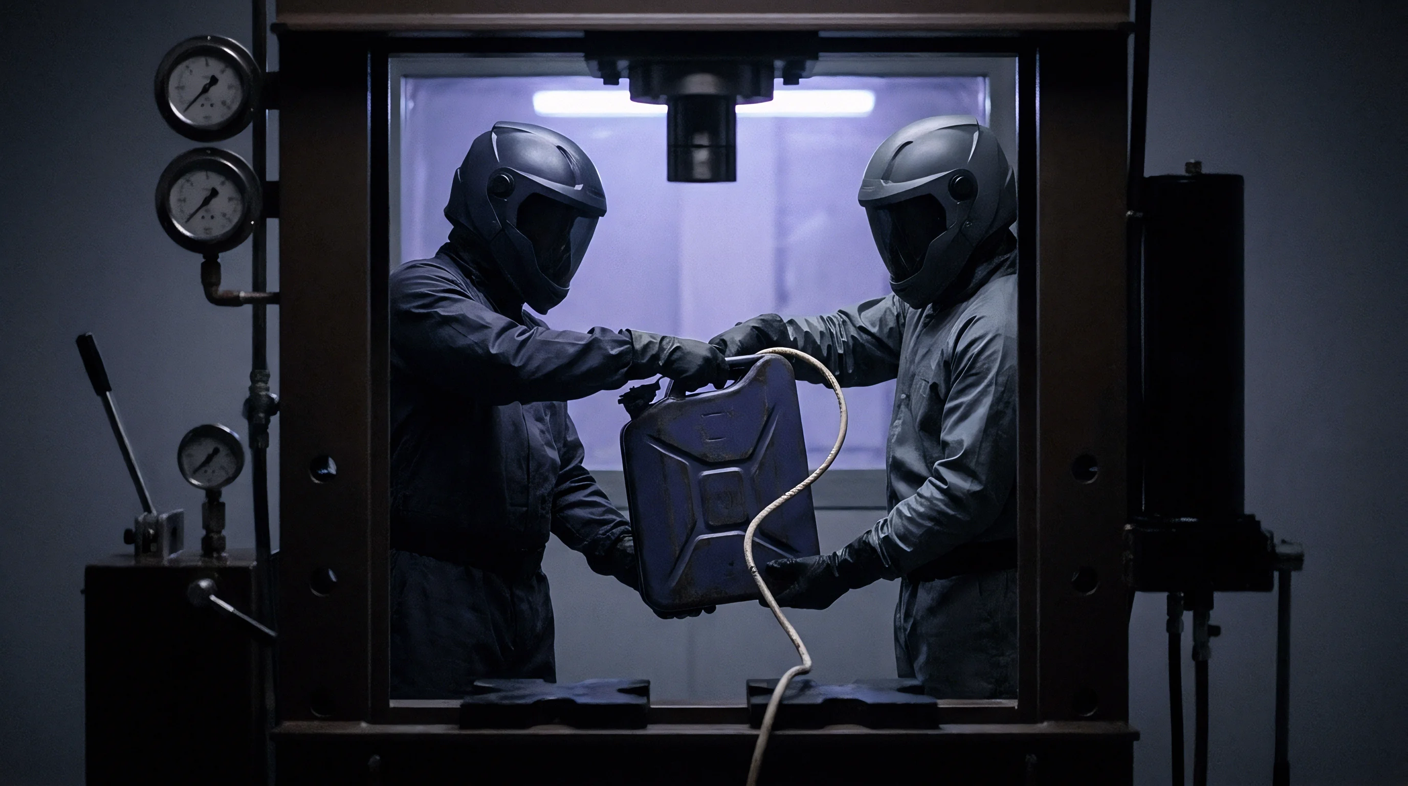
Crush testing evaluates structural integrity under mechanical impact. Standards such as UN 38.3 T.6 and UL 2580 require applying force via round bars, semi-cylinders, or flat platens until reaching fixed displacement, a force threshold (typically 13 kN), or an immediate voltage drop. Actuation speed alters deformation physics, as dynamic shock propagation differs fundamentally from quasi-static loading.
Under quasi-static speeds, such as zero point one millimeter per second, current collectors, coatings, and separators deform plastically in unison. Metallic foils stretch past their tensile limits, tearing cleanly and driving sharp edges through adjacent separator films. This shear failure establishes direct point contact between positive and negative current collectors, creating a localized hard short circuit where intense Joule heating rapidly initiates thermal runaway.
At impact velocities above one hundred millimeters per second, strain-rate sensitivity shifts material behavior. High deformation rates stiffen polymer separators, causing them to fracture in brittle shear rather than yield plastically. Incompressible electrolyte cannot evacuate separator pores quickly enough, generating localized hydraulic pressure that couples adjacent electrode layers and crushes active coatings across broad surface areas.
The resulting internal short is distributed over a wider zone, producing a gradual voltage decay and lower initial current density, though total thermal energy release remains hazardous.
Constrained Life-Cycle Testing Protocols
Constrained life-cycle testing illustrates how mechanical boundary conditions dictate degradation pathways. Benches typically evaluate cells under constant displacement, constant force, or unconstrained expansion. Constant-displacement setups replicate rigid module enclosures, converting volumetric swelling directly into internal stress, whereas constant-force fixtures use calibrated spring packs or pneumatic controls to maintain uniform pressure as cells expand.
| Standard Designation | Test Type | Applied Load / Profile | Pass / Fail Criteria |
|---|---|---|---|
| UN 38.3 T.4 | Mechanical Shock | 150 g peak acceleration, 6 ms duration, 18 total shocks | No mass loss, no leakage, no venting, no drop in V |
| UN 38.3 T.6 | Impact / Crush | 13.0 kN applied force or 50% height crush at 0.1 mm/s | External temp < 170 °C, no disassembly, no fire within 6 hrs |
| IEC 62133-2 Cl. 7.3.8 | Internal Short Circuit | 10 mm x 10 mm L-shaped nickel punch at 0.1 mm/s, 800 N force | No fire, no explosion under localized separator puncture |
| UL 2580 Cl. 18 | Drop Test | 1.0 meter drop onto concrete surface in worst-case orientation | No rupture, no explosion, no hazardous material release |
| SAE J2464 Cl. 4.3 | Dynamic Roll-Over | 360-degree rotation at 0.5 to 1.0 RPM under full constraint | No liquid electrolyte spillage, maintaining isolation resistance |
Data from constrained life-cycle fixtures provides essential design curves for pack engineers. Plotting peak force generation against cumulative equivalent full cycles yields pressure growth models tailored to specific chemistries, electrolytes, and formats. These baseline curves pinpoint the exact cycle where force growth turns from linear expansion to exponential degradation, marking the onset of separator pore collapse or severe electrolyte squeeze-out.
Validation protocols should incorporate multi-axis displacement sensing to detect jellyroll and pouch deformation. Constrained pouch cells frequently exhibit lateral displacement and edge swelling as internal layers displace toward unconstrained seal seams. Laser displacement sensors positioned around the fixture perimeter track lateral expansion, providing early warning of mechanical distortion before electrical performance drops.
An unvented pouch cell rupturing during a high-tonnage crush test destroyed forty thousand dollars in load frames.


Plate
Module endplates provide the primary structural resistance against cumulative cell swelling in dense pouch packs. When twenty to forty large-format pouch cells cycle in series within a single module chassis, total expansion force can exceed fifty kilonewtons near end-of-life. The mechanical design of endplates, tie-rods, side retainers, and elastomeric foam pads dictates whether the assembly maintains required stack pressure or suffers enclosure distortion, fatigue failure, and accelerated cell aging.
Elastomeric compression pads positioned between pouch cells absorb cyclic volume changes. Microcellular silicone, polyurethane, and expanded polypropylene (EPP) display distinct stress-strain hysteresis profiles under compression. Sizing these pads requires balancing initial pre-load against long-term stress relaxation: overly compliant foams allow excessive expansion that induces delamination and lithium plating, while excessively rigid pads act as hard stops that drive peak forces into module endplates.
Endplate design relies on finite element analysis (FEA) to minimize structural mass while preventing bending. Flat aluminum or high-strength steel plates flex under central swelling loads, producing uneven pressure fields where stack corners face heavy clamping while the center drops below target pressure. Ribbed structures, perimeter flanges, and pre-cambered geometries mitigate center deflection to maintain uniform force across the cell active area.
Microcellular silicone foam retains spring-back force far longer than standard polyurethane under elevated module operating temperatures.

Compression Foam Selection and Stress Relaxation Curves
Foam selection requires assessing long-term stress relaxation ~ the decay in restoring force when an elastomer is held at fixed compression. Polyurethane foams lose up to forty percent of their initial spring force within five hundred thermal cycles at fifty degrees Celsius as polymer chains realign. This loss drops stack pre-load below design minimums, allowing unconstrained cell swelling during high-rate charging.
Microcellular silicone foams resist thermal and mechanical relaxation more effectively. Featuring a closed-cell micro-porous structure, silicone maintains stable compression set, retaining over eighty-five percent of initial restoring force across thousands of hours between minus forty and plus eighty-five degrees Celsius. Silicone also provides a progressive spring rate: compliant during initial formation, then stiffening rapidly to prevent excessive swelling at high state of charge.
Embedding phase-change materials (PCM) or aerogel insulation into compression pads provides combined thermal and mechanical management. Aerogel-silicone composites provide high thermal resistance to inhibit thermal runaway propagation between adjacent cells while retaining mechanical compliance to absorb normal volume swings. These composite pads must preserve structural integrity during thermal events, preventing compressive loss during emergency shutdown sequences.

Structural Endwall Deflection and Tie-Rod Tensioning Arithmetic
Sizing endplates and tie-rods requires calculating total cell expansion force. Consider a module containing twenty pouch cells, each measuring two hundred fifty millimeters wide by one hundred fifty millimeters tall, giving an active area of zero point zero three seven five square meters. Maintaining a target static pressure of zero point four megapascals across the electrode area requires a baseline compressive force calculated as follows:
Force = Pressure x Area = 400,000 N/m^2 x 0.0375 m^2 = 15,000 Newtons
At end of life, cumulative irreversible swelling increases stack thickness, compressing silicone pads into their high-modulus region where local stack pressure reaches one point two megapascals. The total force pushing against the endplate rises proportionally:
Peak EOL Force = 1,200,000 N/m^2 x 0.0375 m^2 = 45,000 Newtons (45 kN)
If four steel tie-rods around the perimeter hold the endplates together, each carries one-fourth of the total tensile load. At end of life, each tie-rod sustains eleven point two five kilonewtons of tension. Sizing these steel tie-rods requires calculating the minimum cross-sectional area to prevent plastic yield under peak end-of-life load.
Assuming an alloy steel with six hundred megapascals yield strength and a safety factor of two point zero, the required cross-sectional area per tie-rod is calculated directly:
Required Area = (11,250 N x 2.0) / (600 N/mm^2) = 37.5 square millimeters
This sets the minimum diameter of solid round tie-rods at approximately six point nine millimeters. Using undersized tie-rods causes plastic stretching as the pack ages, relieving internal compression, allowing cells to expand beyond design limits, and accelerating intergranular cathode cracking.

Mitigating Thermal Runaway Propagation through Pressure Relief Channels
Module containment must manage internal gas generation and rapid volume expansion during thermal runaway. When internal short circuits trigger thermal decomposition of active materials and electrolyte, cell pressure spikes within milliseconds. In constrained packs, expanding cells push against adjacent cells with extreme force, risking mechanical damage and cascading thermal propagation.
Module designs mitigate this risk through pressure relief channels, crushable honeycomb structures, or progressive shear pins in endplate assemblies. When internal forces exceed structural design limits ~ such as two point five megapascals during an active failure ~ calibrated shear pins yield to provide expansion volume, directing vented gases into exhaust manifolds while shielding neighboring intact cells from excessive crushing loads.
Engineering guidelines for pack mechanical constraint design are structured as follows:
- Establish Temperature-Compensated Pre-Load Forces that maintain minimum target zero point two megapascal pressure at minus thirty degrees Celsius without exceeding maximum safe baseline limits at sixty degrees Celsius.
- Select High-Resilience Microcellular Silicone Elastomers with proven stress relaxation resistance retaining over eighty-five percent of initial force across five thousand thermal cycles.
- Size Endplate Stiffness to Limit Centroid Deflection to less than zero point five millimeters under peak end-of-life swelling force to guarantee uniform cell surface pressure distribution.
- Calculate Tie-Rod Tensile Strengths with Safety Factors of at least two point zero based on maximum projected end-of-life expansion forces rather than clean factory baseline forces.
- Integrate Controlled Mechanical Pressure Relief Features that deform safely during cell thermal runaway events to prevent crush propagation to neighboring intact cells.
Pack mechanical design balances rigid containment against compliant swelling allowance. Underestimating material relaxation, thermal expansion, or force growth leads directly to structural failure in the field, shell splitting, and catastrophic shorting.
Excessive pack-level endplate clamping risks separator rupture and disputes over warranty coverage for capacity loss.


Filing
Compliance documentation determines whether battery shipments clear port inspections or face impoundment. Transport regulations mandate safety qualification testing for all lithium-ion cells and battery packs under the UN Manual of Tests and Criteria, Section 38.3. Mechanical integrity forms the core of UN 38.3 certification, encompassing mechanical shock (Test T.4), external short circuit under mechanical load (Test T.5), and impact/crush protocols (Test T.6).
Incomplete or deficient UN 38.3 Test Summaries result in cargo rejection by air, ocean, and ground freight carriers.
Regulatory obligations extend beyond initial transport testing. The European Union Battery Regulation (EU 2023/1542) establishes mandatory requirements for carbon footprint declarations, supply chain due diligence, battery passports, and formal durability metrics. Articles 6 and 12 mandate traceable technical dossiers demonstrating that cells maintain specified capacity and power retention thresholds under mechanical, thermal, and electrical stress profiles over their service life.
Importing cells assigns product liability and regulatory compliance to the Importer of Record. If a shipment exhibits structural failure, severe pouch swelling, or thermal runaway in transit or operation, customs authorities audit the technical dossier. Incomplete compression specifications, unverified test summaries, or missing batch inspection certificates expose importers to administrative fines, mandatory recalls, and uninsurable liability.
UN 38.3 Transport Certification for Pre-Constrained Modules
Transporting pre-assembled modules with integrated endplate compression involves specific regulatory requirements under dangerous goods frameworks. UN 38.3 mandates that cells and battery systems undergo testing in the exact physical configuration used during transport. Certifications obtained on unconstrained single pouch cells under Tests T.4 (Shock) and T.6 (Crush) do not transfer to pre-compressed module assemblies.
Pre-constrained modules submitted for UN 38.3 certification must complete mechanical shock testing under Test T.4. The protocol subjects the assembly to eighteen shock pulses across three orthogonal axes. Heavy modules undergo half-sine shock pulses of fifty g peak acceleration over eleven milliseconds, while smaller units are tested at fifteen g over six milliseconds.
Passing requires no casing rupture, cell displacement, mass loss exceeding zero point one percent, voltage drop beyond zero point one volts, or internal short circuits.
Shock test failures frequently stem from tab weld fractures or tie-rod deformation under dynamic acceleration. In an eighteen-kilogram constrained module subjected to a fifty g shock pulse, stack inertia generates transient forces exceeding eight thousand Newtons against endwalls and retaining straps. Fastener yield or tie-rod elongation allows internal layers to shift relative to busbars, shearing current collector tabs and inducing delayed internal short circuits.

EU Battery Regulation Durability Data and Mechanical Degradation Audit
The EU Battery Regulation converts mechanical durability documentation into a mandatory market-access requirement. Manufacturers placing industrial or electric vehicle batteries on the EU market must compile technical dossiers containing verified cycle-life data under defined constraint conditions. Audits verify whether cell performance claims correspond to actual pack operating parameters, including clamping pressure and expected vibration profiles.
Technical dossiers submitted under Article 12 must document capacity retention, resistance growth, and thickness changes across at least one thousand five hundred equivalent full cycles. Testing must follow standards equivalent to IEC 62619 and IEC 61960-3, recording the precise clamping pressures maintained throughout cycling. Utilizing unrealistic laboratory compression loads that cannot be maintained in production packs constitutes regulatory non-compliance, invalidating CE conformity.
Battery Passport provisions under Article 77 require digital records linking each battery serial number to its certified mechanical and electrochemical test history. Technicians, recyclers, and regulatory bodies access data detailing initial assembly pre-loads, expansion history, and state-of-health metrics through QR codes.

Contractual Liability Allocation for Mechanical Failure Modes
Procurement contracts and master service agreements (MSAs) among cell manufacturers, integrators, and OEMs must delineate liability for mechanical failure modes. Warranty terms frequently incorporate strict operating boundaries, excluding coverage if cell swelling exceeds narrow dimensional tolerances or if module clamping forces deviate from nominal factory specifications.
A well-structured procurement agreement defines clear verification protocols and non-conformance thresholds. Contracts should establish incoming inspection procedures per ISO 2859-1 (ANSI/ASQ Z1.4), specifying acceptable quality levels (AQL) for dimensional tolerances, surface flatness, pre-load retention, and tab weld strength.
Compliant dangerous goods shipping dossiers must contain the following documentation items:
- UN 38.3 Test Summary Report complying strictly with UN Manual of Tests and Criteria Part III, Subsection 38.3.5, signed by an accredited ISO/IEC 17025 testing facility officer.
- Material Safety Data Sheet (MSDS / SDS) detailing chemical composition, fire-fighting containment protocols, and mechanical hazard handling rules under GHS revision standards.
- Dangerous Goods Shipper Declaration Form certifying correct UN packaging codes (UN 3480 / UN 3481), Packing Instruction compliance (PI 965 Section IA/IB), and SOC limits below thirty percent.
- Factory Batch Quality Inspection Certificate detailing statistical dimensional verification, tab weld pull-strength tests, and initial baseline cell thickness under zero point three megapascal pre-load.
- EU Declaration of Conformity Dossier containing durability, carbon footprint, and performance compliance evidence mandated under EU Battery Regulation 2023/1542.
Clear contractual assignment of compliance duties and warranty obligations limits financial exposure when quality discrepancies arise. Procurement teams must align legal agreements with transport requirements to audit test certificates, verify testing laboratory accreditations, and enforce contractual terms prior to milestone release.
Procurement contracts specifying UN Manual of Tests and Criteria Section 38.3.5 compliance shift full financial duty to the cell manufacturer when transport authorities impound documentation-deficient freight.