Direct Current Pulse Testing Protocols for Fast Automated Battery Batch Screening
Direct current pulse testing isolates cell ohmic and polarization resistance within milliseconds to reject structural defects before pack integration.


Pulse
A 30-ampere square excitation step applied across a 280-ampere-hour lithium iron phosphate cell for 100 milliseconds produces an instantaneous voltage drop followed by a sloped polarization curve. The initial voltage step reflects purely ohmic drop across the electrolyte, active material layers, current collector foils, and internal tab welds, while the sloped voltage tail represents double-layer charging and solid electrolyte interphase charge transfer kinetics. Standard 1-kilohertz alternating current impedance tests capture only this immediate ohmic response, missing charge transfer degradation and interface oxidation entirely.
High-throughput batch screening demands direct current excitation that captures both ohmic resistance and polarization kinetics in under one second per cell.
High discharge excitation currents pull lithium ions across the electrode-electrolyte interface, creating localized concentration gradients. Excitation pulse durations between 50 milliseconds and 100 milliseconds allow charge transfer overpotentials to stabilize without generating resistive Joule heating that would alter cell temperature during automated testing. Electrolyte dryout increases bulk impedance, but when cell temperature rises during a test, ionic conductivity increases, artificially lowering measured internal resistance and masking real manufacturing defects.
Time Scale Differentiation of Resistance Components
Electrochemical voltage responses uncouple into distinct frequency domains when recorded at microsecond acquisition intervals. High-speed voltage digitizers sampling at 100 kilohertz resolve the instantaneous ohmic voltage drop within the first 50 microseconds of current application. The voltage change occurring between 1 millisecond and 50 milliseconds directly reflects charge transfer resistance across cathode and anode particle interfaces alongside lithium ion transport through the solid electrolyte interphase layer.
| Pulse Duration | Excitation Rate | Primary Electrochemical Response Captured | Dominant Resistance Parameter | Measurement Error Drivers |
|---|---|---|---|---|
| 1 ms to 10 ms | 0.5C to 2C | Inductive bus ring and electrolyte bulk conduction | R0 Ohmic Resistance | Terminal probe inductance and contact bounce |
| 50 ms to 100 ms | 1C to 3C | Solid electrolyte interphase layer transfer and tab interface | RSEI and R0 Combined | Thermal expansion during contact injection |
| 500 ms to 1000 ms | 2C to 5C | Charge transfer kinetics across cathode and anode particle interfaces | Rct, RSEI, and R0 Summed | Joule heating shifting electrolyte ionic conductivity |
| 3000 ms to 5000 ms | 1C to 2C | Solid state lithium ion diffusion within active crystal lattices | Warburg Diffusion Impedance | Cell temperature rise distorting baseline SOC state |
| Data normalized to 25 degrees Celsius ambient temperature at 50 percent state of charge under rigid mechanical stack compression. | ||||
State of charge governs polarization magnitude significantly. At 50 percent state of charge, open circuit cell voltage sits on a flat electrochemical plateau where charge transfer resistance stays stable across minor state-of-charge variations. High or low states of charge increase polarization overpotentials dramatically due to steep solid-state diffusion gradients at electrode particle surfaces.
Standardizing batch screening at exactly 50 percent state of charge eliminates state-of-charge variance as a source of false rejections.
A 100-millisecond discharge load at 2C rate at 50 percent state of charge isolates charge transfer resistance changes down to 0.05 milliohms when thermal drift remains below 0.2 degrees Celsius.
Overpotentials grow under repeated high current. Fast automated screening lines use automated thermal drift correction algorithms to scale measured voltage drops back to a 25 degrees Celsius baseline. Temperature sensor response times must match conveyer index speeds to prevent uncalibrated thermal offsets from compromising sorting accuracy.
Higher excitation currents accelerate double layer charge saturation, whereas lower currents leave microsecond voltage responses buried inside voltage digitizer instrument noise.


Fixture
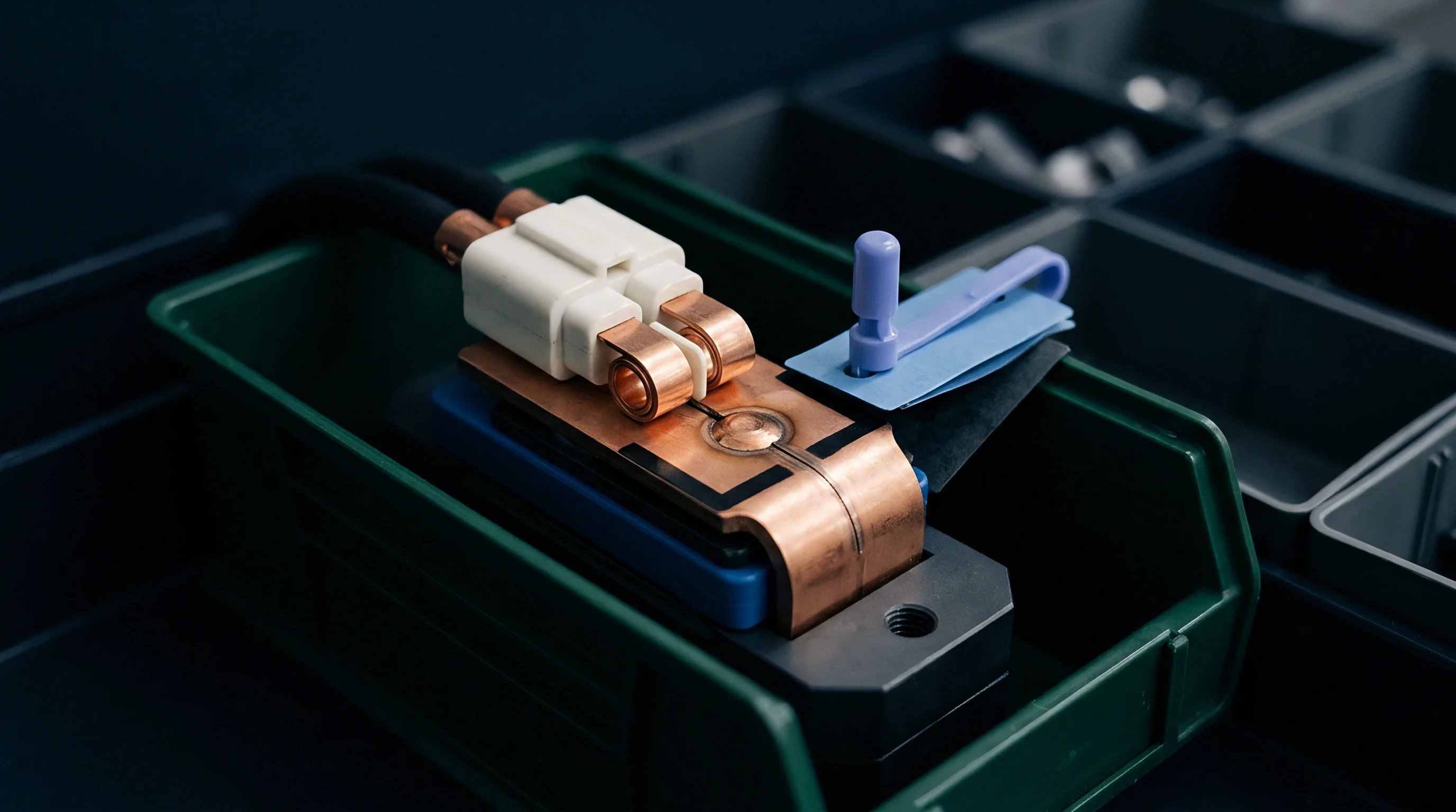
Pneumatic clamping actuators on automated screening conveyers introduce physical contact variations that directly alter millivolt measurements. Precise direct current pulse testing relies on minimizing parasitic fixture impedance, yet standard spring-loaded pogo pins generate contact resistance variability between 0.2 milliohms and 1.5 milliohms depending on mechanical insertion force, tip plating oxidation, and terminal surface contamination. This contact noise easily swamps the subtle 0.05 milliohm resistance shifts that indicate internal welding defects or electrolyte under-filling.
Eliminating fixture contact error requires dedicated four-wire Kelvin contact assemblies operating with controlled mechanical force application. Separate current-carrying pins and voltage-sensing pins contact the cell terminal independently. Current flows through outer high-current copper alloy pins while voltage drop measurements execute across inner gold-plated sensing needles that resist oxidation and draw negligible current.
This configuration cancels probe tip contact resistance and lead wire impedance from the acquisition loop entirely.

Four Wire Kelvin Contact Dynamics
Separate current delivery paths from sense leads directly at the physical point of terminal interface. Automated inline clamping mechanisms execute strict motion control sequences during cell engagement to preserve measurement integrity across high-speed sorting runs.
- Pneumatic cylinder advances sense probes against clean terminal metal at 10 Newtons force to crush surface oxide layers.
- Sense circuit continuity check executes within 2 milliseconds to confirm stable metal contact before applying high current pulses.
- Current source fires square excitation profile while voltage acquisition channel records at 100 kilohertz sampling frequency.
- Acquisition hardware isolates steady state voltage drop within 50 microseconds before current interruption.
- Pneumatic retract solenoids release clamp pressure only after excitation current drops to zero to protect pin plating from arc pitting.
Solid-state switching arrays perform faster than mechanical contactors, eliminating contact bounce duration completely. Mechanical contactors introduce 5 to 15 milliseconds of tip vibration during closing, corrupting the critical initial microsecond window where bulk ohmic resistance separates from polarization impedance.
| Terminal Material | Probe Pin Tip Design | Applied Contact Force | Interface Resistance | Lifetime Insertion Cycles |
|---|---|---|---|---|
| Bare Aluminum | Multi-point Crown Beryllium Copper | 10 N | 0.12 mΩ ± 0.03 mΩ | 50,000 |
| Nickel Plated Steel | Serrated Gold Plated Copper | 8 N | 0.08 mΩ ± 0.01 mΩ | 120,000 |
| Laser Cleaned Copper | Pneumatic Flat Gold Alloy | 12 N | 0.04 mΩ ± 0.005 mΩ | 200,000 |
| Oxidized Aluminum | Single Spear Point Carbide | 6 N | 0.45 mΩ ± 0.15 mΩ | 15,000 |
Clean terminal metallurgy and consistent pneumatic force prevent pin contact impedance from masking internal cell degradation.
High current pulses generate magnetic fields around test cables that induce unwanted voltage spikes in adjacent high-impedance sense lines. Shielded twisted-pair sensing wires routed orthogonally to current buses prevent electromagnetic coupling from distorting millivolt relaxation signals. Elevated batch internal resistance often stems from oxidation on test bench contacts rather than poor tab weld consistency inside the cell casing.


Anomaly
Latent structural flaws inside packaged cells manifest as distinct departures from expected transient voltage decay profiles. Manufacturing defects like metallic particle contamination, foil slitting burrs, micro-porosity collapse, and partial tab weld delamination alter cell impedance profiles long before capacity testing reveals degradation, as separator defects cause localized electron leakage. Pulse excitation exposes these anomalies by driving high current densities through internal fault paths.
A cell with an internal copper burr piercing the separator displays abnormal transient voltage relaxation after load removal. High localized current density creates heating across the micro-short path, altering internal charge transfer kinetics and accelerating local self-discharge. Automated sorting software flags cells whose post-pulse voltage recovery rate falls outside statistical tolerance bands.

How Does Transient Polarization Reveal Latent Micro Shorts?
Separator defects create localized electron leakage paths that discharge double layer capacitance immediately upon current removal. Tracking voltage decay slopes during the first 10 milliseconds post-pulse exposes sub-milliohm leakage bridges that remain completely invisible to low-current open circuit voltage meters.
- Separator micro-punctures generate rapid voltage relaxation decays immediately following load termination due to localized internal discharge currents.
- Defective tab ultrasonic welds trigger abrupt millivolt spikes during initial current application resulting from constrained contact cross-sectional areas.
- Electrolyte starvation elevates charge transfer resistance across both electrodes while maintaining near-normal bulk electrolyte ionic conductivity readings.
- Active material delamination increases overall polarization overpotential while causing asymmetric charge and discharge voltage relaxation signatures.
Tab weld failure represents a severe fire hazard in high-power applications. When an ultrasonic tab weld suffers from poor tool clamping pressure or dirty anvil horns, the effective contact surface area drops. Under a 2C pulse, this reduced area forces current through a narrow metallic bridge, generating localized heating and an instantaneous voltage drop spike that exceeds nominal cell ohmic standards by several standard deviations.
Automated voltage slope analysis during current interruption detects separator punctures long before self discharge measurements register thermal loss.
Electrolyte distribution variations alter charge transfer uniformities across large-format prismatic electrodes. Poorly wetted separator zones create high local impedance regions that distort the current density distribution during heavy discharge pulses. Passing cells with unrecognized tab weld defects into pack assembly leads to localized heating during high rate discharge, premature thermal shutdown, and field failure.


Threshold
Pass bounds established for high-speed screening lines balance factory yield against field failure risks through statistical population modeling. Setting screening cutoffs involves evaluating production lot resistance distributions under standardized test conditions. In a typical production batch of 50,000 280-ampere-hour lithium iron phosphate cells, nominal ohmic resistance centers at 0.18 milliohms with a standard deviation of 0.012 milliohms, while nominal charge transfer resistance centers at 0.22 milliohms with a standard deviation of 0.018 milliohms.
Standard quality screening applies upper acceptance limits at three standard deviations above lot mean values. For bulk ohmic resistance, the upper pass boundary calculates to 0.216 milliohms. For charge transfer resistance, the upper bound sets at 0.274 milliohms.
Cells displaying values above these calculated thresholds get rejected immediately. Relying solely on 1-kilohertz alternating current testing accepts cells with normal bulk resistance of 0.18 milliohms even when charge transfer resistance reaches an abnormal 0.35 milliohms due to severe electrolyte degradation or cathode coating defects.

Mathematical Derivation of Acceptance Pass Bounds
Statistical distribution parameters dictate strict upper and lower cutoffs for measured voltage drops across production lots. Screening limits incorporate both absolute milliohm limits and relative asymmetry ratios calculated between charge and discharge excitation steps.
- Ohmic cutoff calculation sets upper limit at three standard deviations above lot mean to isolate abnormal tab welding or foil thickness variations.
- Polarization limit assignment flags cells exceeding two standard deviations from nominal double-layer relaxation targets to catch electrolyte filling anomalies.
- Asymmetry ratio verification compares charge pulse response against discharge pulse response to identify early stage lithium plating risks.
Evaluating charge versus discharge pulse asymmetry provides crucial secondary defect isolation. A healthy lithium cell exhibits virtually identical ohmic resistance under brief discharge and charge pulses. When metallic lithium plating coats the anode surface, charge acceptance drops rapidly, causing charge overpotential to exceed discharge overpotential by more than 15 percent under identical pulse magnitudes.
| Cell Chemistry and Format | Test Pulse Profile | Nominal Ohmic Limits | Polarization Upper Limit | Expected Rejection Yield |
|---|---|---|---|---|
| LFP Prismatic 280Ah | 100 ms at 1C (280A) | 0.18 mΩ ± 0.03 mΩ | 0.28 mΩ | 0.85 percent |
| NMC 811 Pouch 50Ah | 50 ms at 2C (100A) | 0.42 mΩ ± 0.05 mΩ | 0.65 mΩ | 1.40 percent |
| LTO Cylindrical 20Ah | 10 ms at 5C (100A) | 0.25 mΩ ± 0.02 mΩ | 0.35 mΩ | 0.30 percent |
| NMC 622 Prismatic 120Ah | 100 ms at 1.5C (180A) | 0.31 mΩ ± 0.04 mΩ | 0.48 mΩ | 1.10 percent |
Automated sorting systems group passing cells into tight resistance bins with maximum bandwidths of 0.02 milliohms per bin. This tight grouping prevents severe cell-to-cell voltage imbalances when operating in long series strings inside energy storage systems. Whether fast excitation protocols can fully replace 24-hour open circuit voltage aging protocols for detecting ultra-slow separator degradation remains actively disputed across quality engineering laboratories.


Tariff
Customs valuation classifications and landed cost calculations depend directly on whether incoming cell batches pass certified screening protocols before customs clearance. Receiving un-screened cell shipments at import facilities transfers all commercial risk of hidden cell defects directly onto the buyer. Inspecting cells inside bonded warehouses before paying import duties prevents tax outlay on defective units destined for scrap.
Replacing full 24-hour capacity cycle tests with 100-millisecond direct current pulse screening drops dockside inspection costs dramatically. Fast screening cuts station residence times from hours to seconds per cell, allowing 100 percent lot verification rather than sparse statistical sampling. Identifying defective batches at the port allows immediate filing of formal customs duty drawback claims and commercial carrier insurance claims before cells move into factory inventories.
Financial Exposure from Unscreened Batch Variations
Uncaught internal resistance anomalies multiply warranty liabilities once cells are welded into high voltage series strings. Returning defective cells to overseas suppliers requires hazardous material dangerous goods shipping clearance, expensive certified packaging, UN 38.3 transport safety compliance documentation, and complex customs re-export paperwork.
Rejecting a defective 40-foot container holding 3,000 prismatic cells on arrival saves thousands of dollars in freight and duty expenses. Early automated screening isolates vendor quality drift before cell batches integrate into modules where teardown costs exceed cell replacement values.
A purchase agreement clause mandating direct current pulse screening upon container arrival allows buyers to reject entire shipments when batch yield falls below 98.5 percent.
Contractual acceptance terms specify exact screening pulse parameters including excitation current rate, pulse width, state of charge, ambient test temperature, and pass threshold distributions. Incorporating IEC 62660-1 pulse resistance verification limits into supply contract acceptance schedules legally obligates vendors to cover re-testing and return shipping costs for failing cell lots.