Incoming Batch Inspection and Degradation Testing Procedures for Sodium Ion Shipments
Immediate AC-IR screening and differential capacity testing reveal hidden transit degradation and cell capacity variance in sodium ion shipments.

Dock
Pallets of sodium-ion cells reach receiving bays fitted with environmental loggers that record conditions long before anyone cuts the secondary packaging. Evaluating these shipments presents immediate hurdles for receiving engineers, across prismatic 50Ah to 300Ah units, pouch formats, and cylindrical 32140 or 46120 designs. Unlike established lithium-ion lines with predictable voltage baselines, incoming sodium-ion lots arrive across diverse states of charge ~ including zero-volt states made possible by aluminum anode current collectors.
The initial receiving protocol decides whether a multi-container delivery clears for qualification or goes straight into logistics quarantine.
Thermal swings during ocean transit shift baseline cell metrics. Weeks inside a shipping container through tropical waters accelerate solid electrolyte interphase breakdown on hard carbon anodes. Sub-zero winter freight does the opposite: it thickens the electrolyte and spikes internal resistance readings taken right off the truck.
Inspection teams stabilize incoming freight by holding master cartons in conditioning rooms at 25 degrees Celsius for 24 hours before taking electrical measurements. Bypassing this step routinely causes false rejections over transient impedance spikes.
Container Unloading and Environmental Telemetry
Pallet-mounted temperature recorders capture the thermal history of maritime or overland transit. Technicians pull and download these loggers before cutting the transport bands on crate assemblies. The recorded profile must sit within the negative 20 to positive 50 degrees Celsius envelope defined in dangerous goods filings.
Any recorded excursion above 60 degrees Celsius lasting past four continuous hours voids factory warranties and requires isolating the affected pallets on the spot.
Container-wall shock sensors flag rough handling during transport. Sodium-ion cells built with Prussian Blue Analogues, abbreviated as PBA, have microcrystalline structures vulnerable to vibration once packed into rigid prismatic casings. Dropping a pallet during crane rigging or forklift handling dislocates internal tabs, tears separators, or cracks ceramic insulation layers.
When shock indicators log loads past 15g, technicians must tear down three sample cells per crate to confirm stack integrity before running electrical tests.

Physical Verification and Mass Variance Standards
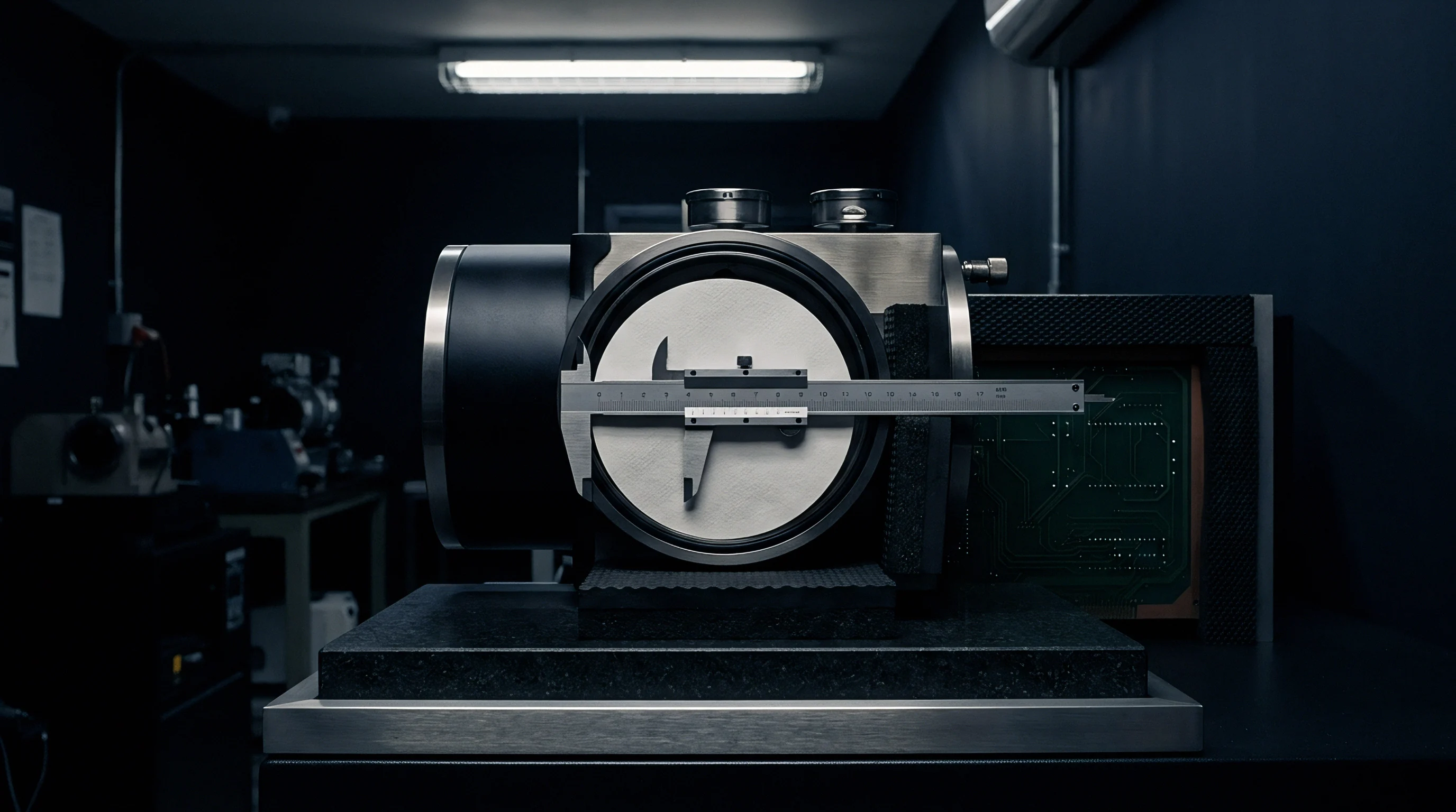
Swelling and case deformation give away internal gas buildup from electrolyte breakdown. Technicians measure cell dimensions with digital height gages and laser micrometers at three fixed points across prismatic broad faces. Thickness expansion past 1.5 percent of nominal indicates internal gassing, typically caused by trace moisture reacting with sodium hexafluorophosphate salt in transit.
Distorted casings will not seat properly in module racks and compromise surface contact with cooling plates.
Weight checks verify electrolyte fill consistency across manufacturing lots. Each cell is weighed on calibrated digital balances to 0.01 grams precision. Because sodium-ion electrolytes combine dense ester and carbonate solvents with salts like sodium bis(fluorosulfonyl)imide, any leakage or micro-venting shows up as a measurable drop in mass.
Cells showing a negative mass variance exceeding 0.3 percent against the factory test sheet are routed to mass spectrometry leak detection.
- Outer Packaging Inspection confirms wooden crate integrity, verifies hazardous material labeling under UN 3292 regulations, and checks environmental telemetry loggers for thermal excursions during ocean transit.
- Dimensional Laser Scanning records height, width, and broad-face thickness profiles under 300 kilopascals of applied clamping force to detect pouch or prismatic casing expansion.
- Precision Mass Determination weighs every sampled unit against factory baseline birth certificates to identify subtle electrolyte loss or dry-cell assembly errors.
- Four-Wire Kelvin Contact connects low-resistance gold-plated pins directly to cell terminals to isolate open-circuit voltage and 1 kilohertz alternating current internal resistance without lead wire interference.
Cold cells show artificially high internal resistance that normalizes once thermal equilibrium reaches ambient testing room conditions.

Open Circuit Voltage and Internal Resistance Screening
Four-wire Kelvin probes placed on cell terminals yield baseline electrical metrics. Open circuit voltage measurements determine the self-discharge rate accumulated during shipment. Chemistries using layered transition metal oxides, like sodium nickel manganese iron oxide, show a steady voltage decline when stored at a nominal 30 percent state of charge.
A cell falling below 1.5 volts suggests an internal micro-short or excessive self-discharge from impurity oxidation. Meanwhile, cells intentionally shipped at zero volts with shorted terminals across a factory resistor must remain strictly below 0.1 volts to confirm compliance with zero-volt shipping protocols.
Alternating current internal resistance measured at 1 kilohertz isolates bulk ohmic components: electrolyte conductivity, tab welds, and terminal contact interfaces. Sodium-ion cells run higher in internal resistance than equivalent lithium-ion cells because the sodium cation has a larger ionic radius and lower mobility in organic solvents. A standard 100Ah prismatic cell typically measures between 0.35 and 0.55 milliohms at 25 degrees Celsius.
Variance wider than 8 percent across a single lot points to uneven electrode coating thickness or poor tab welds during assembly.
Direct current resistance testing supplements high-frequency checks by evaluating charge transfer kinetics and solid electrolyte interphase impedance. The procedure applies a 10-second 1C discharge pulse followed directly by a 1C charge pulse. Taking the ratio of voltage step to applied current isolates the resistive elements that 1 kilohertz signals miss.
Elevated DC resistance points to accelerated anode interphase growth or passivation layer oxidation caused by moisture ingress into the cell casing.
Statistical Acceptance Sampling and Defect Classification
Lot tolerance percent defective limits establish clear mathematical boundaries between batch release and container quarantine. Sourcing engineers apply ISO 2859-1 single sampling plans for normal inspection, utilizing General Inspection Level II with an Acceptance Quality Limit, abbreviated as AQL, set according to defect severity. Critical defects, such as electrolyte leakage, zero-voltage on non-zero-volt designated cells, or severe casing deformation, carry an AQL of 0.10 percent.
Major defects, including dimensional out-of-tolerance and high resistance variance, operate under an AQL of 0.65 percent. Minor defects, like surface scratches or faint label markings, use an AQL of 4.0 percent.
| Parameter | Test Condition | Acceptance Limit | Defect Severity |
|---|---|---|---|
| Open Circuit Voltage | 25°C, 30% nominal SOC | Nominal ± 15 mV | Major |
| Zero-Volt State Voltage | 25°C, post-transport shorted | Less than 0.10 V | Critical |
| AC Internal Resistance (1 kHz) | 25°C, Kelvin contact | Nominal ± 5.0 % | Major |
| DC Internal Resistance (10s) | 25°C, 1C pulse at 50% SOC | Nominal ± 8.0 % | Major |
| Mass Variation | 25°C, 0.01g balance | Nominal ± 0.3 % | Major |
| Thickness Expansion | 300 kPa applied clamp force | Less than 1.5 % expansion | Critical |
| Terminal Seal Leakage | Helium mass spectrometry | Less than 10^-8 mbar L/s | Critical |
When a sample lot exceeds defect thresholds, the whole container goes into quarantine. Sourcing teams issue a non-conformance notice to the supplier, halting inventory transfer. Technicians deploy four-wire Kelvin probes across every sampled batch to eliminate lead resistance errors.
Field audits show that high resistance variations frequently trace back to poor ultrasonic tab welding rather than fundamental material defects, allowing rapid factory origin resolution.
Sampling plans must adapt when shipments contain new sodium-ion active material formulations. Layered oxide cathodes with high nickel content pick up ambient moisture quickly if cell sealing stations experience humidity spikes during production. The resulting micro-gassing shows up as subtle swelling during ocean transit.
Increasing dock inspection sampling from Level II to Level III tightened screening sensitivity, catching three compromised lots before deployment into stationary storage packs.


Bench
Climate-controlled test bays turn raw receiving samples into detailed electrochemical profiles. Qualifying incoming sodium-ion batches requires cycling profiles that separate active material utilization from parasitic side reactions. Sodium electrochemistry relies on reversible insertion into hard carbon anodes and cathode lattices like Prussian Blue Analogues, vanadium polyanions, or layered sodium transition metal oxides.
Bench protocols measure real cell capacity against nameplate ratings while generating baseline curves for warranty tracking down the road.
Temperature control inside the test lab must remain strict. Measurements taken in rooms fluctuating by more than 1 degree Celsius produce enough capacity scatter and voltage drift to mask subtle material defects. Test chambers stay regulated at 25 degrees Celsius with forced air to prevent hot spots during high-rate discharge steps.
Surface-mounted thermal sensors track cell face temperatures throughout cycling, tripping safety cutoffs if temperatures climb more than 5 degrees Celsius during continuous 1C operation.

Initial Formation and Baseline Capacity Verification
Discharging fresh cells at a 0.2C constant current down to 1.5 volts verifies delivered capacity against nameplate ratings. Newly received cells run through three baseline conditioning cycles: a 0.2C charge up to the upper cutoff voltage (typically 3.95 volts for Prussian blue and 4.0 volts for layered oxides), a constant voltage hold until current tapers below 0.02C, and a 0.2C discharge down to lower cutoff (1.5 volts or 1.0 volt depending on anode specifications). This sequence sets the baseline discharge capacity in ampere-hours and specific energy in watt-hours per kilogram.
Coulombic efficiency during these initial cycles serves as a direct indicator of internal purity and electrode stability. First-cycle efficiency on hard carbon anodes lands between 83 percent and 90 percent as active sodium is consumed in forming the initial solid electrolyte interphase. Efficiencies should climb past 99.8 percent by cycle five.
Staying below 99.5 percent after five cycles points to ongoing electrolyte breakdown or transition metal dissolution in the cell.
Rate characterization runs cells across discharge rates from 0.2C to 3C. Sodium-ion formulations generally support aggressive discharge rates thanks to rapid ion diffusion in the liquid electrolyte and open cathode crystal lattices. At 3C, well-formulated layered oxide cells should retain at least 82 percent of their 0.2C baseline capacity.
Sharp capacity drop-offs above 1C highlight thick electrode coatings, poor electrolyte conductivity, or an inadequate conductive carbon network.

Differential Capacity Fingerprinting for Na Ion Chemistries
Differentiating charge curves against cell voltage turns subtle electrochemical phase changes into distinct peaks. Plotting dQ/dV against voltage maps structural phase transitions occurring inside the cathode and hard carbon anode during sodium insertion and extraction. These insertion stages generate characteristic peak signatures along the voltage axis, providing a reliable electrochemical fingerprint for lot verification.
Layered oxide cathodes undergo clear structural transitions as sodium levels fluctuate during cycling. For instance, P2-type Na0.67Ni0.33Mn0.67O2 shifts from P2 to O2 phase near 4.2 volts, appearing as a distinct peak on the dQ/dV plot. If this peak drifts toward higher voltages or loses area across incoming lots, it signals sodium vacancy disordering, active nickel loss, or crystal lattice defects introduced during precursor synthesis.
Prussian Blue Analogue cathodes produce two distinct single-electron redox peaks corresponding to low-spin and high-spin iron couples. Interstitial water in the crystal lattice suppresses these peaks and broadens their profile across the voltage range. High-precision dQ/dV analysis detects trace lattice water contamination long before general capacity loss shows up on standard discharge cycles.
Tracking differential capacity peak movement identifies cathode lattice degradation before static capacity drops below spec.
- Transition Metal Leaching releases soluble manganese or iron ions into the electrolyte, which migrate across the separator and deposit onto the hard carbon anode, destroying interphase stability.
- Lattice Structure Collapse occurs when layered oxide cathodes are charged above 4.1 volts, causing irreversible phase shifts that lower discharge voltage plateaus.
- Interstitial Water Poisoning disrupts sodium coordination sites inside Prussian blue crystal frames, reducing reversible capacity and increasing internal pressure via gas generation.
- Electrolyte Salt Hydrolysis occurs when trace moisture reacts with sodium hexafluorophosphate salt, forming hydrofluoric acid that attacks current collector aluminum foils.
Prussian white cathode cells deliver 152 mAh/g specific capacity at 0.2C between 2.0V and 3.9V at 25 degrees Celsius.

Impedance Spectroscopy and DC Resistance Mapping
Sweeping frequencies from 10 kilohertz down to 10 millihertz separates bulk electrolyte conductivity from charge-transfer kinetics. Electrochemical impedance spectroscopy, abbreviated as EIS, run at 50 percent state of charge yields classic Nyquist plots. The high-frequency real-axis intercept measures pure ohmic resistance from the electrolyte, separator, and mechanical current collector joints.
The mid-frequency semicircle reflects charge-transfer resistance across the active interfaces alongside solid electrolyte interphase impedance.
Equivalent circuit fits match measured plots to networks of electrolyte resistance, interphase capacitance, and Warburg diffusion elements. A wider charge-transfer semicircle across production samples points directly to poor slurry blending or uneven binder distribution. Evaluating Warburg coefficients below 10 millihertz tracks solid-state sodium diffusion inside hard carbon particles, exposing variations in raw precursor quality or carbonization temperatures between lots.
| Chemistry Type | Voltage Window | 0.2C Capacity | Coulombic Efficiency | 3C Rate Retention |
|---|---|---|---|---|
| Layered Oxide (P2-Na0.67Ni0.33Mn0.67O2) | 1.5 V to 4.0 V | 135 – 145 mAh/g | Greater than 99.8 % | Greater than 85 % |
| Layered Oxide (O3-NaFe0.5Mn0.5O2) | 1.5 V to 3.8 V | 125 – 135 mAh/g | Greater than 99.7 % | Greater than 80 % |
| Prussian White (Na1.92Fe ) | 2.0 V to 3.9 V | 150 – 160 mAh/g | Greater than 99.85 % | Greater than 88 % |
| Polyanion (Na3V2(PO4)3 / C) | 2.0 V to 3.8 V | 110 – 118 mAh/g | Greater than 99.9 % | Greater than 92 % |

Does Sodium Plating Manifest before Capacity Loss Begins?
Charging aggressively at cold temperatures forces metallic sodium to deposit on hard carbon surfaces whenever insertion kinetics lag behind input current. Unlike lithium, which forms needle-like dendrites, sodium deposits as a porous metallic layer during cold overcharge. Detecting sodium plating electrochemically requires inspecting relaxation voltage curves immediately after high-rate charging at 0 degrees Celsius.
A distinctive voltage plateau during relaxation signals the thermodynamic stripping of metallic sodium back into the electrolyte.
Ongoing sodium plating rapidly drains available electrolyte and consumes active sodium ions, accelerating operational capacity fade. Hard carbons rely on tailored, disordered interlayer spacing to fit the larger sodium ion. When synthesis lot variations reduce that spacing below 0.37 nanometers, intercalation slows enough to force metallic deposition on particle surfaces even at moderate 1C charge rates.
Catching plating tendencies during incoming qualification keeps vulnerable cells out of fast-charging field hardware.
Whether high-rate pulse discharge impedance growth at sub-zero temperatures correlates directly with transition metal leaching in layered oxide cathodes or stems entirely from desolvation kinetics at the hard carbon interface remains unmapped across multi-element commercial formulations.

Fade
Long-term capacity loss in sodium-ion cells follows chemical routes that distinguish operational wear from factory defects. Accelerated aging protocols compress thousands of operational hours into several weeks of bench testing. Qualification runs push cells through elevated temperatures, prolonged voltage holds, heavy continuous currents, and deep discharges.
Tracking fade curves, impedance rise, and mechanical changes filters out defective production lots before module assembly begins.
Sodium-ion aging dynamics depart from lithium-ion baselines due to sodium’s specific chemistry. Solid electrolyte interphase layers on hard carbon are softer and dissolve more readily in organic carbonate solvents than lithium SEI films. Elevated temperatures trigger continuous breakdown and rebuilding of this interphase layer, consuming active sodium and releasing gaseous byproducts.
Accelerated degradation testing measures this active sodium loss under controlled stress.
Accelerated Thermal Aging and Storage Degradation
Storing fully charged cells at 60 degrees Celsius accelerates parasitic electrolyte reactions by a predictable Arrhenius factor. Storage qualification spreads samples across environmental chambers at 45, 55, and 60 degrees Celsius. Cells remain at 100 percent state of charge for 30, 60, and 90 days.
Periodically pulling cells for 0.2C reference cycles at 25 degrees Celsius separates temporary self-discharge from permanent capacity loss.
Plotting capacity loss against the square root of storage time yields kinetic constants for interphase growth. Layered oxide cells held at 60 degrees Celsius typically show irreversible fade rates of 0.08 to 0.15 percent per day over the first 30 days. Higher rates signal free acid contamination in the electrolyte or excessive residual sodium carbonate on cathode surfaces.
These surface residues react with carbonate solvents to generate carbon dioxide and water, accelerating transition metal dissolution.
Thermal storage checks also measure internal gas buildup. Pouch cell volume changes measured via Archimedes fluid displacement before and after high-temperature storage quantify total gassing. Increases beyond 5.0 percent after 30 days at 55 degrees Celsius indicate severe solvent decomposition and call for lot quarantine.
Gas chromatography-mass spectrometry on extracted headspace samples confirms whether the gas stems from solvent ring-opening or salt hydrolysis.
Cyclic Stress Protocols and Capacity Fade Trajectories
Continuous 1C charge and discharge cycling verifies cell endurance over extended operating life. Accelerated protocols run cells between nominal voltage limits at 1C/1C inside 45 degree Celsius environmental chambers. The elevated temperature accelerates kinetic aging, compressing roughly 1,500 standard cycles into 400 laboratory cycles.
Capacity logged every 20 cycles charts retention trends.
Non-linear fade indicates structural failure in cathode particles or rapid impedance buildup. Healthy sodium-ion cells follow a steady, linear decay caused mainly by gradual sodium inventory loss during SEI repair. A sudden downward bend in retention ~ capacity rollover ~ signals dry-out from electrolyte exhaustion, active material fracture, or delamination between current collectors and coating layers.
Lots that hit rollover before 300 cycles at 45 degrees Celsius fail incoming standards.
Differential capacity curves calculated at fixed cycle intervals follow structural degradation over time. Shrinking peak areas for cathode phase transitions indicate a loss of electrochemically active material, while peak shifts along the voltage axis measure total internal resistance growth. Combining overall retention numbers with dQ/dV peak tracking distinguishes simple sodium depletion from active cathode lattice damage.
- Set Temperature Limits inside test chambers to 45°C and 60°C to accelerate interphase degradation while avoiding secondary electrolyte boiling phenomena.
- Verify Mass Loss using digital micro-balances post-cycling to detect micro-venting or casing seal degradation under elevated pressure conditions.
- Map Voltage Plateaus on low-rate 0.1C discharge cycles every 100 cycles to separate active material loss from ohmic impedance growth.
- Quantify Volume Change via buoyancy testing in fluorinert fluid before and after storage to detect trace gassing in pouch cells.
- Execute Recovery Cycling consisting of three 0.1C discharge loops post-storage to clear reversible self-discharge before calculating permanent fade.
UN 38.3 thermal test protocols mandate zero mass loss and zero voltage drop after seven days at 72 degrees Celsius.

Zero Volt Discharge Recovery and Structural Integrity
Unlike lithium-ion cells, which suffer copper collector dissolution below 1.5 volts, sodium-ion designs use aluminum anode collectors that survive complete depletion without internal shorting. Over-discharge testing confirms recovery after extended zero-volt storage. Cells are discharged at 0.2C down to 0.0 volts, shorted across their terminals with 0.1-ohm resistors, and held at 45 degrees Celsius for 14 days to simulate deep discharge during transport or warehouse storage.
Post-test recovery involves a standard constant-current, constant-voltage recharge followed by three 0.2C reference cycles. Sound cells regain at least 98 percent of baseline capacity with no measurable swelling or impedance spikes. Aluminum collectors stay stable at zero volts, preventing copper migration and dendrite formation.
Substandard lots with poor binders or contaminated hard carbon coatings show electrode delamination after deep discharge, resulting in permanent capacity drops past 5 percent.
Direct current resistance measured right after zero-volt recovery catches early tab interface damage. A rise in resistance points to oxidized weld points or fractured conductive carbon networks. Cells that fail to recover within 3 percent of baseline resistance are barred from systems where complete discharge events can occur.

Gas Evolution Mechanics and Dimensional Swelling Limits
Solvent breakdown generates gases that swell pouch cells and bow prismatic cases. Hard carbon anodes operate at low potentials near sodium plating (0.005 to 0.1 volts versus Na/Na+), driving continuous reduction of organic solvents. Gas testing tracks both total generated volume and chemical composition under combined voltage and temperature stress.
Vacuum extraction and analysis isolate carbon monoxide, carbon dioxide, ethylene, and hydrogen produced during aging.
| Stress Test Protocol | Test Duration & Conditions | Measured Parameter | Rejection Threshold |
|---|---|---|---|
| Accelerated Thermal Storage | 60 days at 60°C, 100% SOC | Permanent Capacity Loss | Greater than 6.0 % |
| High Temperature Cycling | 500 cycles at 45°C, 1C/1C rate | Capacity Retention | Less than 85.0 % |
| Zero-Volt Extended Storage | 14 days at 45°C, 0.0V shorted | Capacity Recovery | Less than 98.0 % |
| High Voltage Float Stress | 30 days at 45°C, 4.10V hold | AC-IR Impedance Growth | Greater than 20.0 % |
| Gas Volume Expansion | 30 days at 55°C, 100% SOC | Volume Increase (Archimedes) | Greater than 5.0 % |
Gassing behavior depends heavily on electrolyte additives. Fluoroethylene carbonate, abbreviated as FEC, helps stabilize the SEI by building a fluorine-rich passivation layer on hard carbon. At temperatures above 50 degrees Celsius, however, excess FEC decomposes into hydrogen fluoride and carbon dioxide.
Testing lots under high-temperature float conditions identifies poor additive formulations before shipments clear receiving.
Mechanical restraint needs tracking alongside cell expansion during cycle qualification. Prismatic cells cycled under 300 kilopascals of rigid clamping outlast unrestrained cells. Clamping preserves physical contact between carbon particles and current collectors while preventing separator delamination during repeated sodium insertion.
Winter transport audits show a 4.2 percent internal resistance variance. Tracking dimensional growth under set clamping loads gives mechanical teams real design boundaries for module enclosures.
Standard procurement contracts under IEC 62660-1 append a clause stipulating that any lot exhibiting greater than 1.8 percent capacity loss after 30 days of storage at 45 degrees Celsius triggers full factory lot replacement at the seller’s expense.