Silicon Anode Expansion Mechanics under Solid Encapsulation
Solid silicon anode expansion demands 5 MPa stack clamping to prevent void delamination, imposing module hardware mass penalties that cut pack energy density.

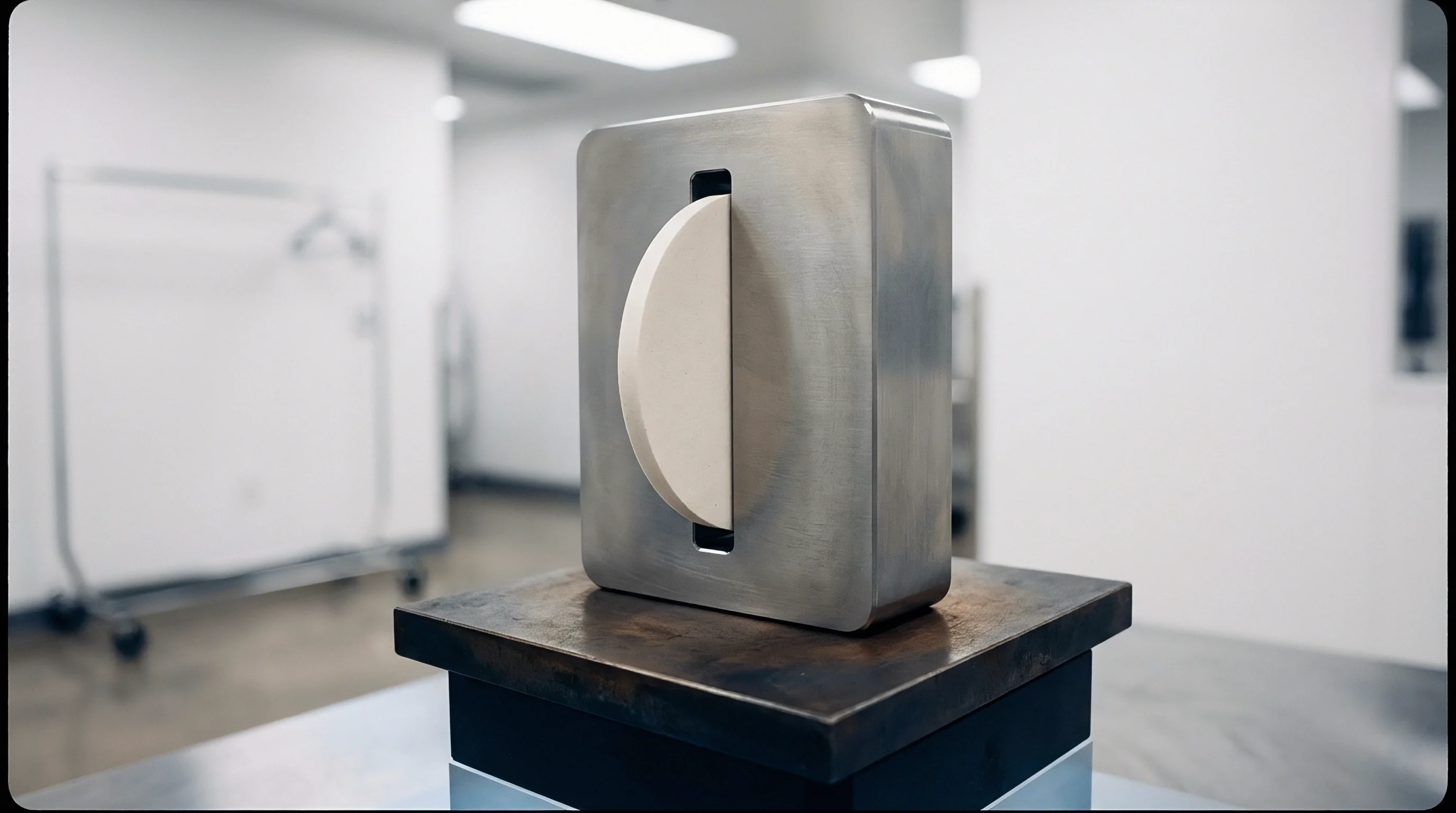
Bulk
Dilatometer pins resting on unconstrained micro-silicon composite electrodes register vertical displacement rates exceeding 0.85 micrometers per milliampere-hour of lithiation per square centimeter. In pouch configurations, pure crystalline particles expand from an initial lattice parameter of 5.43 angstroms into amorphous lithiated phases that terminate at Li15Si4, scaling individual particle volumes by 280 to 300 percent. This sequence forces outward displacement against rigid cell boundaries.
While pure silicon delivers four thousand milliampere-hours per gram at theoretical saturation, replacing porous liquid-filled separators with dense ceramic or glassy separators forces that volume surge against an unyielding wall. The resulting boundary mechanics govern cell longevity, stack integrity, and commercial viability.
Solid separators have elastic moduli between 15 and 180 gigapascals. Because the expanding active material cannot displace a liquid phase to vent into microscopic separator pores, it deforms directly against the dense separator, setting up severe triaxial stress inside the composite negative electrode. Unconstrained foil pulverizes within fifty cycles.
Without active compliance, the electrode either buckles laterally, drives shear fractures through the solid electrolyte separator, or extrudes into void spaces along current collector edges.
Thick composite electrodes with uneven particle packing fail faster than uniform sub-micron dispersion layers.
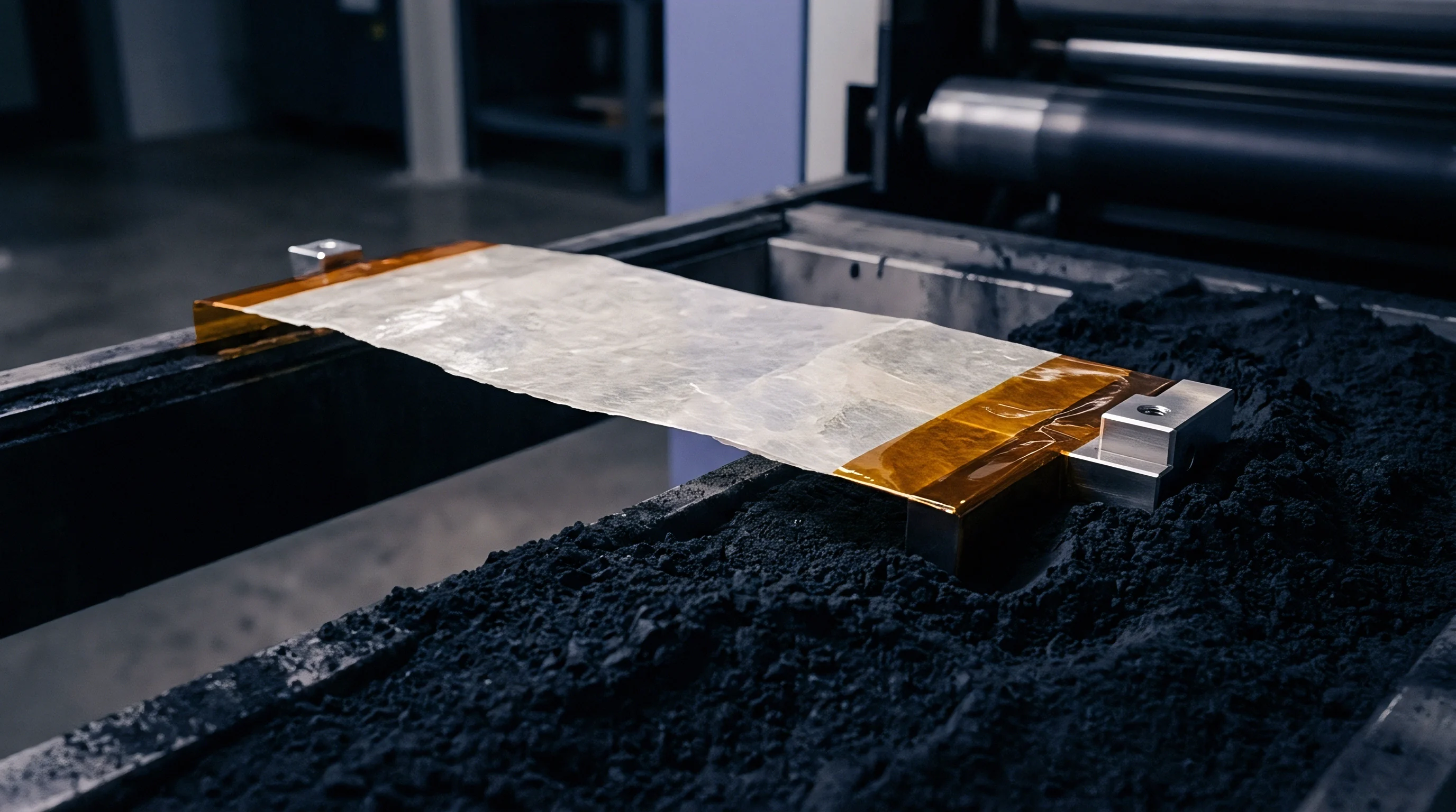
Chemo-Mechanical Expansion Limits of Lithiated Silicon
Lithium insertion into pristine crystalline silicon proceeds via a sharp two-phase reaction front. Below 50 millivolts versus Li/Li+, amorphous Li_xSi transforms abruptly into crystalline Li15Si4. This phase shift brings an instantaneous volume jump of approximately 10 percent within the lithiated shell, generating hoop stresses that exceed the 1.5 gigapascal fracture limit of the silicon particles themselves.
Particle cracking begins at the outer lithiated rim during the first half-cycle, exposing fresh silicon directly to surrounding materials.
Solid encapsulation fundamentally alters the stress field around each particle. In liquid systems, fracture drives perpetual electrolyte consumption and continuous solid electrolyte interphase growth. In solid architectures, fractured particle facets pull away from the solid conductor instead, doubling contact resistance across ten cycles.
This microscopic isolation strands unreacted active material away from ionic pathways. As a result, the irreversible loss of active mass degrades capacity retention to less than 70 percent within two hundred cycles unless external clamping holds the interfaces together.
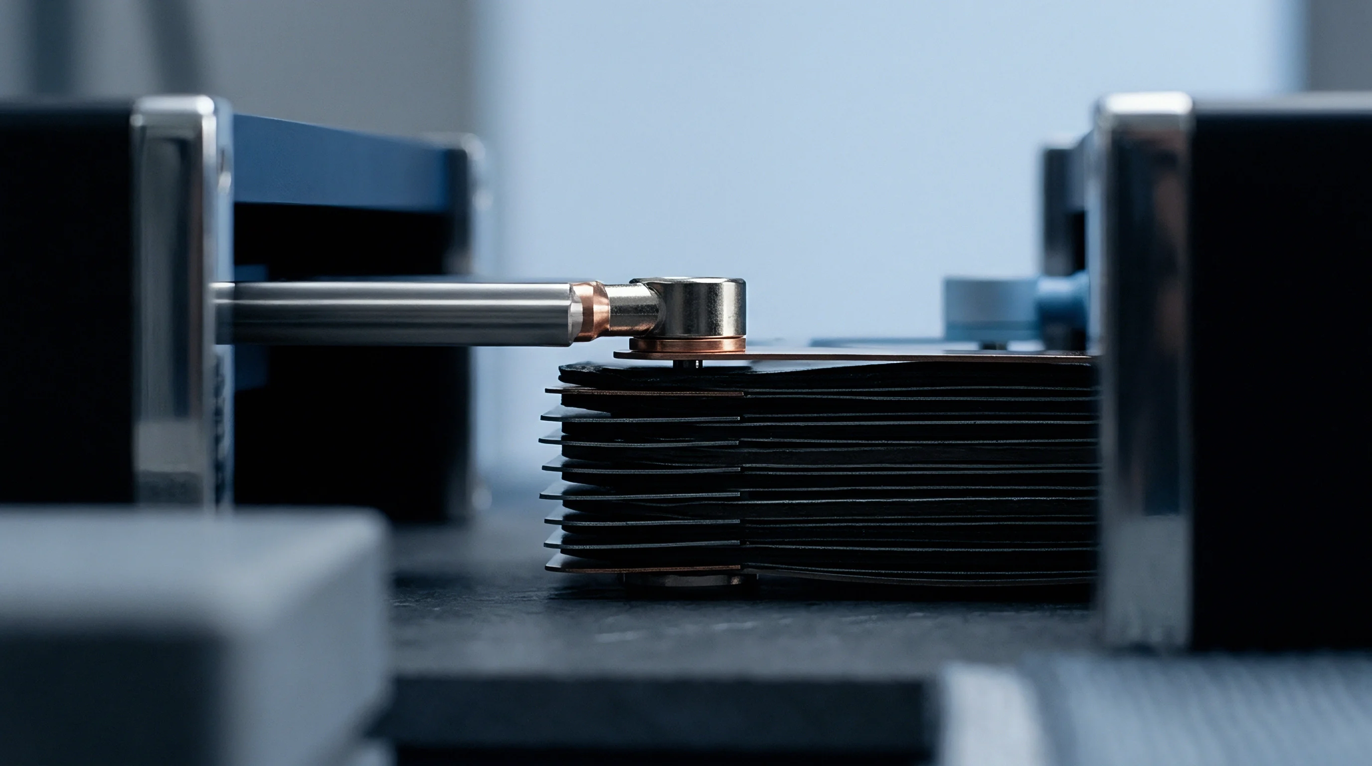
Phase Transformations during Delithiation Cycles
Delithiation reverses this volumetric trajectory, pulling the active grains back toward their original dimensions. Silicon contracts during dealloying while the surrounding dense electrolyte remains mechanically rigid. While lithiation collapses interior void space, delithiation contraction opens interfacial cavities between silicon particles and the solid electrolyte matrix.
These empty cavities act as ionic bottlenecks, spiking local charge transfer resistance from 12 ohms square centimeter to over 350 ohms square centimeter at room temperature.
Repeated breathing cycles subject the active particle boundary to alternating tensile and compressive loads. Delithiation exerts tensile fatigue on the matrix, opening microcracks in brittle sulfide or oxide electrolyte networks and severing the percolation pathways needed for uniform current distribution. Thicker coatings amplify the degradation, peeling unevenly from the current collector along foil edges.
Electrode balance shifts across successive cycles as localized dead zones accumulate throughout the coating thickness.
Cell builders manage this phenomenon by pairing sub-micron silicon particles with ductile carbonaceous conductors, setting cell operational windows well above the low-voltage cutoff where catastrophic particle pulverization occurs.


Stress
Thin-film piezoelectric sensors embedded in solid-state pouch cells capture local stress concentrations reaching 1.2 gigapascals at full lithiation, against a stack perimeter pressure window of five megapascals. Solid electrolytes respond to these localized loads according to their crystal structures, grain boundaries, and shear moduli: sulfide electrolytes deform under lower stress, whereas garnet oxides shatter under tensile deflection. Balancing these mechanical regimes dictates whether an encapsulated silicon cell maintains ionic transport or develops catastrophic internal short circuits.
Maintaining microscopic contact requires continuous stack pressure. Applying uniform external load drives plastic flow in softer sulfide solid electrolytes like Li10GeP2S12 and Li6PS5Cl, closing cavities formed during delithiation. Excessive pressure, however, crushes the active silicon or triggers creep in lithium-silicon alloys, forcing active material into grain boundaries within the solid separator.
The separator cracks under localized shear, meaning its mechanical failure threshold establishes the upper boundary of permissible stack clamping.
Stack pressures maintained between 4.5 and 5.5 megapascals preserve interface contact while avoiding premature ceramic fracture.

How Does Mechanical Pressure Regulate Interface Voids?
External compressive loads alter the chemical potential of lithium within the negative electrode. Mechanical pressure introduces a mechanical work term into the Gibbs free energy equation, shifting the equilibrium potential of the alloying reaction upward by approximately 5 to 12 millivolts under a 5 megapascal stack load. This shift alters the driving force for lithium diffusion, accelerating creep in both the lithiated silicon alloy and the adjacent solid electrolyte.
The creeping material fills micro-cavities before they detach from the ionic percolation network.
Without sufficient clamping, voids coalesce into planar delamination gaps. Lithium transport halts across ruptured interfaces, crowding current into whatever contact points survive. Local current densities at these remaining bridges surge past 25 milliamperes per square centimeter, far exceeding the critical current density of the solid separator.
Dendritic lithium nucleates at these constriction points during subsequent recharge cycles. Mechanical confinement suppresses void formation by maintaining contact stresses above the yield point of the softer component in the composite electrode.

Yield Limits of Solid Electrolyte Separators
Ceramic and glassy solid separators possess finite shear and tensile strengths that dictate allowable expansion stresses. Oxides such as Li7La3Zr2O12 demonstrate fracture toughness values between 0.8 and 1.2 MPa m^0.5, rendering them vulnerable to localized stress concentrations generated by expanding silicon agglomerates. Sulfides present lower shear moduli, allowing moderate plastic deformation at stack pressures between 5 and 15 megapascals, yet they succumb to intergranular shear when subjected to asymmetric expansion gradients.
| Electrolyte Class | Specific Chemistry | Young Modulus (GPa) | Yield Strength (MPa) | Critical Stack Pressure (MPa) | Dominant Failure Mode |
|---|---|---|---|---|---|
| Garnet Oxide | Li7La3Zr2O12 (LLZO) | 145 to 160 | 1200 to 1400 | 2.5 to 4.0 | Brittle transgranular cracking |
| Argyrodite Sulfide | Li6PS5Cl (LPSCl) | 22 to 28 | 210 to 260 | 5.0 to 8.0 | Intergranular creep and shear voiding |
| Thio-LISICON | Li10GeP2S12 (LGPS) | 24 to 30 | 180 to 230 | 4.0 to 6.5 | Grain boundary void nucleation |
| Halide | Li3InCl6 (LIC) | 18 to 25 | 150 to 190 | 3.0 to 5.0 | Compressive yield and micro-cleavage |
The interaction between the expanding silicon active layer and the solid separator triggers specific failure mechanisms when external clamping fails to hold the assembly within structural tolerances:
- Interfacial Delamination occurs when delithiation shrinkage stresses exceed the adhesion energy of the active layer to the solid separator, creating insulating planar gaps.
- Transgranular Separator Cleavage results from non-uniform silicon expansion generating localized bending moments that surpass the critical fracture toughness of brittle oxide separators.
- Creep-Induced Penetration develops under excessive stack loads where lithiated silicon extrudes into separator surface defects, creating high-conductivity pathways for dendrite growth.
- Edge Shear Rupture manifests along the perimeter of the electrode coating where discontinuous lateral constraints produce severe localized shear strains.
Selecting an incorrect clamping load damages the cell components during cycle life, causing rapid capacity fade through contact loss under low pressure or precipitating dead short circuits through ceramic rupture under excessive force.

Brace
External containment hardware transforms theoretical solid-state pouch cells into functional battery modules. Because pouch cells bulge past allowable tolerances during initial formation, the surrounding chassis structure controls dimensional stability throughout cycling. Rigid containment fixtures must absorb cyclic displacement while maintaining stack pressure within the narrow operational window.
The cell module relies on precision spring packs, elastomeric foam pads, or active hydraulic clamping systems integrated into the battery tray architecture.
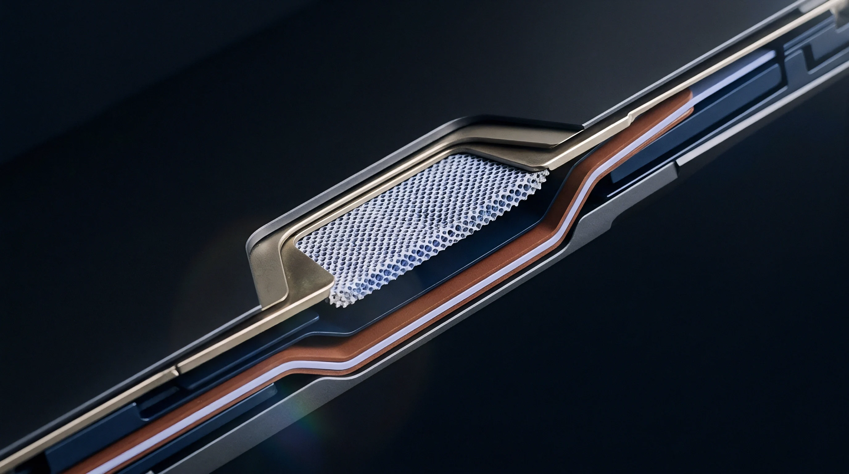
Spring packs absorb this volumetric breathing, with Belleville disc springs arranged in series-parallel stacks to supply high load capacity within compact vertical envelopes. A 100-millimeter by 100-millimeter cell cycling at 3.0 milliampere-hours per square centimeter expands by approximately 18 to 25 micrometers per single-layer repeat unit during lithiation. In a 24-layer pouch stack, total stack displacement reaches 0.43 to 0.60 millimeters.
The containment brace accommodates this travel without allowing stack pressure to drift outside acceptable thresholds.
Mechanical containment fixtures must maintain uniform face pressure across the entire cell surface area regardless of lithiation state.
Spring Pack Sizing for Volumetric Breathing
Calculating spring compliance begins with the allowable pressure delta between full state of charge and complete discharge. A standard target window holds stack pressure between 4.0 megapascals at discharged state and 6.5 megapascals at fully charged state. Across a cell face area of 0.01 square meters, these pressures correspond to clamping forces between 40 kilonewtons and 65 kilonewtons.
The allowable force delta across the full 0.60-millimeter expansion travel equals 25 kilonewtons.
The spring rate of the module containment system matches this compliance envelope. A spring rate of approximately 41.7 kilonewtons per millimeter satisfies the force window. Using stiffer spring arrangements causes stack pressures to spike beyond 12 megapascals during charge, crushing softer sulfide solid electrolytes or cracking fragile oxide separators.
Insufficient spring stiffness allows pressure to fall below 2.0 megapascals during full discharge, causing immediate interfacial delamination.
| Mechanism Type | Stroke Capacity (mm) | Pressure Variation Range | Mass Penalty (kg/kWh) | Volumetric Overhead |
|---|---|---|---|---|
| Belleville Disc Springs | 0.5 to 2.5 | Plus or minus 15 percent | 1.8 to 2.4 | 8 to 12 percent |
| Elastomeric Microcellular Foam | 0.2 to 1.0 | Plus or minus 35 percent | 0.6 to 0.9 | 5 to 7 percent |
| Rigid Fixed-Gap Tie Rods | 0.0 to 0.1 | Spikes exceed 300 percent | 0.8 to 1.2 | 2 to 4 percent |
| Active Pneumatic Bladders | 1.0 to 5.0 | Plus or minus 2 percent | 3.5 to 5.2 | 14 to 18 percent |

Constant Displacement versus Constant Pressure Tooling
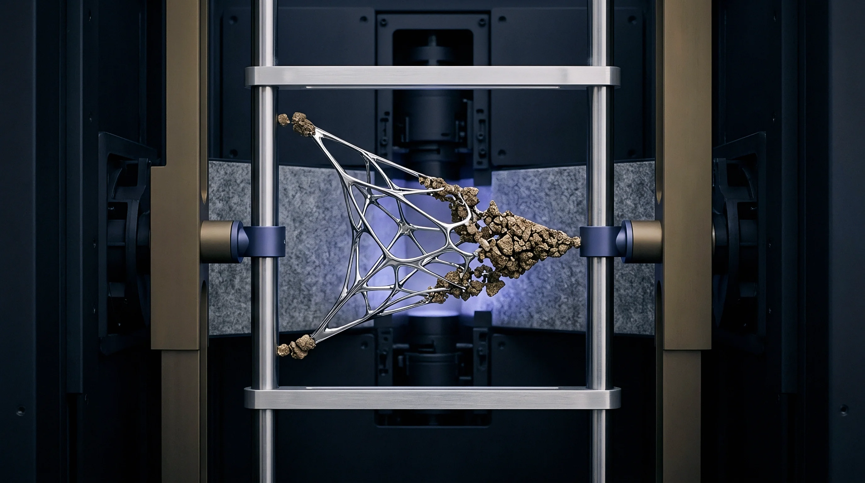
Tooling design choices dictate module lifetime and assembly complexity. Constant-displacement fixturing locks the cell stack within rigid endplates held by zero-clearance steel tie rods. As the silicon expands, stack pressure rises exponentially according to the combined elastic moduli of the internal cell components.
In fixed-gap tooling, local pressure spikes surpass 20 megapascals at 100 percent state of charge. Coulombic efficiency drops below ninety percent.
The mechanical containment hardware satisfies distinct system criteria during procurement and line integration:
- Uniform Pressure Distribution mandates endplate deflection limits under 0.05 millimeters across the active face to prevent localized edge pinching.
- Dynamic Travel Accommodation absorbs cumulative thermal expansion alongside cyclic electrochemical breathing without mechanical binding.
- Creep Resistance Under Continuous Load prevents progressive loss of baseline clamping force across a ten-year vehicle or stationary operating lifespan.
- Dielectric Isolation Boundaries insulate structural clamping plates from active current collectors to prevent chassis ground fault loops.
Standard rigid-wall module enclosures are frequently specified for pilot builds, yet those assemblies show early cell degradation when unyielding walls convert normal expansion into localized structural failure.

Screening
In-line quality assessment of encapsulated solid-state cells demands inspection techniques capable of distinguishing interfacial delamination from separator microcracking. Conventional open-circuit voltage checks and single-frequency 1-kilohertz AC internal resistance measurements fail to identify subsurface physical detachment. Solid-state manufacturing lines integrate high-frequency acoustic emission monitoring, active ultrasonic scanning, and non-destructive stack dilatometry during cell formation cycles.
Titanium casings add significant mass penalty. Screening fixtures capture mechanical compliance signatures before cells proceed to module integration.
Formation protocols for silicon-solid electrolyte cells differ fundamentally from liquid battery routines. Initial lithiation must proceed at low rates, typically between C/20 and C/15, while mounted inside calibrated pressure jigs. Controlled C-rates allow plastic relaxation to accommodate local volume surges, preventing localized shear fracture along separator boundaries.
Cells displaying anomalous pressure excursions during the initial charge cycle carry internal physical defects that cause field failures.
Acoustic emission energy spikes occurring during initial delithiation indicate irreversible ceramic separator fracture.

Where Do Solid Encapsulation Layers Fracture First?
Fracture initiation concentrates at the geometric boundaries of the negative electrode coating. Along the perimeter edges, the gradient between expanding composite material and bare current collector foil creates localized shear stresses. Ultrasonic transmission scans reveal that edge delamination precedes surface crack propagation by dozens of cycles.
When the solid electrolyte separator extends beyond the negative electrode boundary, this edge discontinuity produces a cantilever bending stress on the brittle ceramic overhang.
Subsurface micro-flaws inside the separator layer represent secondary failure sites. Voids, agglomerated binder particles, or sintering pores act as stress concentrators where local mechanical tension exceeds the theoretical cleavage strength of the material. Acoustic sensors detect acoustic bursts corresponding to crack initiation events at these internal flaw sites during the delithiation phase.
When burst counts exceed thirty events per square centimeter during formation, the cell demonstrates accelerated capacity loss during subsequent cycling.
Acoustic Emission and Electrochemical Diagnostic Steps
Non-destructive qualification relies on synchronized multi-modal data collection throughout initial qualification cycling. The verification sequence validates mechanical compliance alongside electrochemical performance:
- Mount the cell within a variable-pressure test clamp calibrated to 5.0 megapascals with integrated contact load cells and acoustic transducers.
- Apply a vacuum degassing cycle followed by baseline electrochemical impedance spectroscopy across a frequency spectrum of 100 kilohertz to 10 millihertz.
- Execute formation lithiation at a constant rate of C/20 while monitoring expansion displacement and acoustic burst counts continuously.
- Measure peak stack pressure at 100 percent state of charge to verify that compliance mechanisms prevent excursions beyond 7.0 megapascals.
- Perform formation delithiation at C/20 while recording the pressure drop signature to detect hysteresis anomalies indicative of internal void coalescence.
- Conduct post-formation ultrasonic transmission imaging to verify that active interfacial contact exceeds 98 percent across the electrode area.
Under quality framework IEC 62660-2 clause 6.2, deviation in dimensional stability beyond five percent of nominal stack thickness voids certified mechanical compliance, requiring lot segregation and containment review.

Package
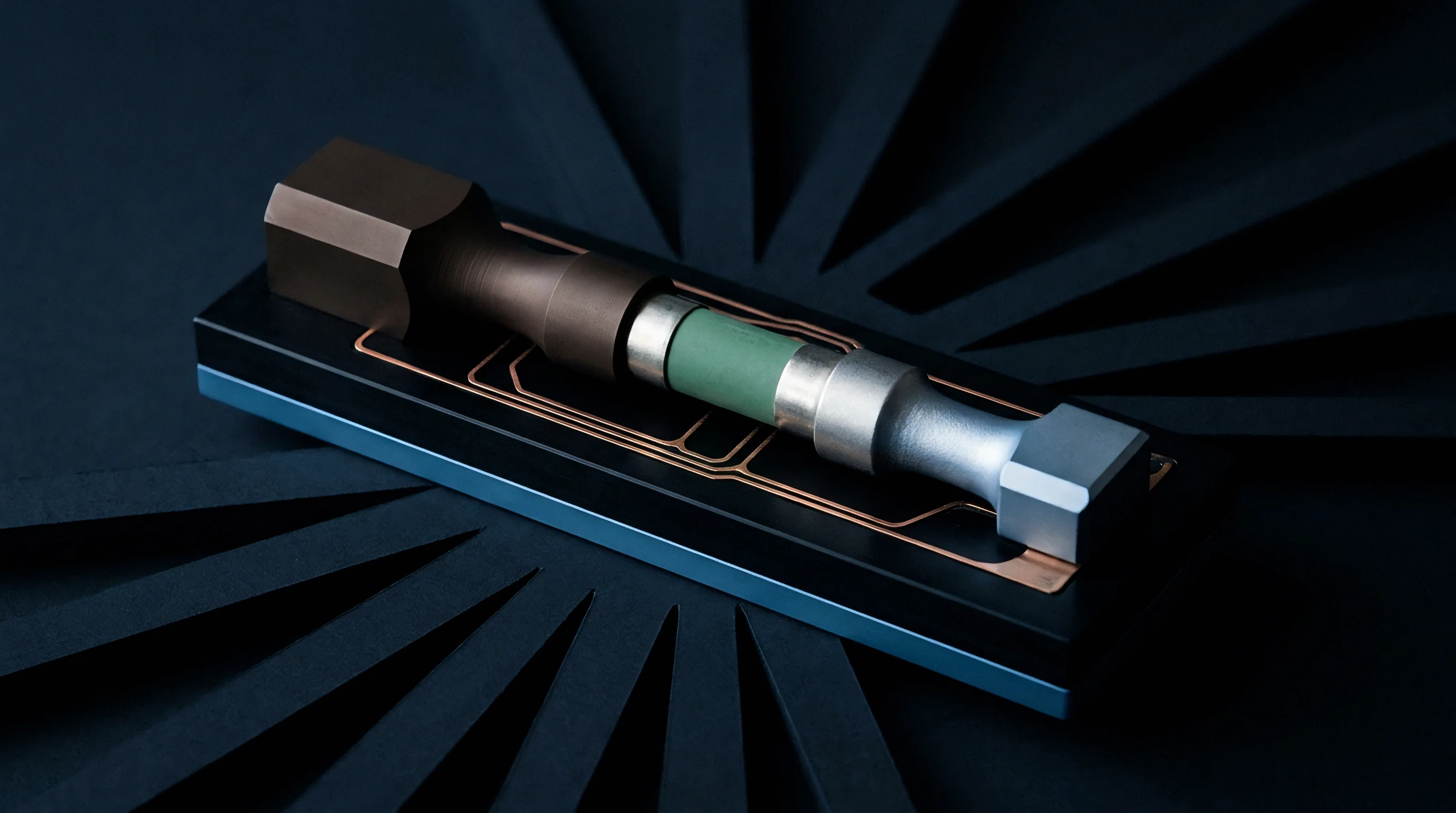
Translating cell-level energy density into usable pack-level performance exposes the true engineering cost of mechanical encapsulation. Solid-state silicon pouch cells achieve cell-level volumetric energy densities between 800 and 1000 watt-hours per liter under unconstrained laboratory conditions. Enclosing these cells inside heavy structural containment braces, high-compliance spring assemblies, and reinforced module bulkheads degrades pack-level metrics.
The structural overhead required to exert 5 megapascals of continuous stack pressure reduces effective system-level density significantly.
Module packaging efficiency drops from typical liquid lithium-ion levels of 75 to 80 percent down to 55 to 62 percent in solid-state systems. Heavy steel or aluminum endplates, high-tensile tie bolts, and compliance pads consume both mass and enclosure space. Thermal management systems face additional constraints, since heat rejection must occur through thick structural pressure plates that introduce thermal contact resistance.
System developers must optimize structural architecture to balance energy density against required clamping force.
Volumetric Energy Density Penalties at Stack Level
Quantifying the system penalty requires modeling the structural mass and volume demanded by stack pressure containment. An unconstrained cell stack delivering 100 kilowatt-hours requires approximately 110 liters of net cell core volume. Holding this stack under 5 megapascals of pressure across twenty cell groupings demands substantial mechanical reinforcement.
Structural titanium or high-strength steel tie bolts represent significant non-active mass additions.
| Containment Pressure (MPa) | Cell Core Density (Wh/L) | Clamping Hardware Mass (kg) | Pack Structural Overhead (L) | Net Pack Density (Wh/L) | System Mass Penalty (%) |
|---|---|---|---|---|---|
| 0.5 (Passive Foam) | 920 | 14.2 | 18.5 | 685 | 3.5 |
| 2.0 (Light Spring Pack) | 905 | 38.6 | 34.2 | 590 | 8.2 |
| 5.0 (Heavy Belleville Stack) | 880 | 86.4 | 62.8 | 495 | 17.8 |
| 10.0 (High-Load Active Frame) | 850 | 148.0 | 105.4 | 410 | 29.5 |
Thermal Conduction across Dynamic Interfacial Boundaries
Heat dissipation during high-rate discharge presents severe challenges inside mechanically constrained solid-state modules. Thermal conductivity through solid sulfide electrolytes averages 0.5 to 0.7 watts per meter-kelvin, which is lower than conventional liquid electrolytes saturating porous polyolefin separators. As the active silicon particles expand and contract, microscopic thermal contact resistance at the electrode-separator interface fluctuates dynamically.
At high discharge rates, heat accumulates rapidly inside the cell core.
Cooling plates positioned at module ends must transfer heat across structural pressure plates and spring assemblies. This series thermal resistance elevates core cell operating temperatures by 8 to 15 degrees Celsius relative to liquid cell modules under equivalent cooling flow rates. Elevated operating temperatures accelerate creep in sulfide electrolytes, lowering the required clamping pressure while increasing side reactions that consume active lithium.
Liquid cold plates integrated directly into intermediate pressure shims add fluid routing complexity and increase leak risks within high-voltage enclosures.
The unresolved question remains whether material advances in compliant solid electrolytes can reduce required stack clamping pressures below 1 megapascal before high module hardware mass penalties eliminate the volumetric energy density advantages of solid silicon anodes.