Designing Compliant Compression Frameworks for Silicon Composite Anode Module Breathing
Compliant compression frameworks balance silicon anode breathing between 0.1 and 0.8 MPa using tailored elastomeric pads and springs to avoid separator collapse.

Swell
Inserting lithium into pure silicon compounds expands theoretical lattice volume by more than 300 percent. To balance specific capacity with mechanical structural life, commercial cell formulators blend silicon suboxide or silicon-carbon nano-composites into synthetic graphite at mass fractions between 5 percent and 15 percent, as unconstrained packs fail early. At these commercial blend levels, active electrode stacks show bulk breathing of 8 percent to 22 percent at full state of charge during initial cycles.
Solid electrolyte interphase accumulation on freshly cracked silicon surfaces adds permanent, irreversible thickness gains of 5 percent to 12 percent across five hundred full cycles.
Because mechanical conditions dictate electrical longevity, holding an active silicon composite module at fixed exterior boundary dimensions without internal compliance forces electrochemical expansion directly into compressive stress against the cell faces. Internal stack stresses exceed 2.5 MPa by cycle two hundred. This pressure crushes the open pore network of typical 12-micron to 16-micron polyolefin separators, starving the negative electrode of liquid electrolyte and driving rapid lithium metal plating along anode edges.
Conversely, applying zero initial clamping force allows composite anode particles to delaminate from copper current collector foils as they breathe, destroying electrical percolation networks and stranding active material within sixty cycles.

Volumetric Expansion across Silicon Loadings
Active material formulations alter the breathing envelope throughout cycling. Synthetic graphite alone displays an intercalation expansion plateau around 10 percent at lithiation, whereas silicon breathes far more violently. Adding carbon-coated silicon suboxide (SiOx) forms irreversible lithium orthosilicate and lithium oxide phases during initial lithiation that buffer subsequent cycling, reducing active volume swings relative to pure silicon particles.
Silicon-carbon (Si-C) nano-composites enclose nanoscale silicon grains inside a porous conductive carbon matrix, dampening external dimension changes until electrolyte decomposition products fill the internal particle voids.
| Anode Chemistry Blend | Reversible Cycle Breathing | Irreversible Growth At 500 Cycles | Unconstrained Face Displacement | Target Initial Preload |
|---|---|---|---|---|
| Synthetic Graphite Reference | 4.2% to 5.5% | 2.8% to 4.1% | 0.28 mm | 0.15 MPa to 0.25 MPa |
| Graphite with 5 wt% Si-C | 7.5% to 9.2% | 5.8% to 7.2% | 0.62 mm | 0.20 MPa to 0.35 MPa |
| Graphite with 10 wt% Si-C | 11.8% to 14.5% | 8.5% to 11.0% | 1.15 mm | 0.30 MPa to 0.45 MPa |
| Graphite with 8 wt% SiOx | 9.0% to 11.2% | 10.2% to 13.5% | 0.98 mm | 0.25 MPa to 0.40 MPa |
| Graphite with 15 wt% SiOx | 15.5% to 20.5% | 14.0% to 18.2% | 1.75 mm | 0.35 MPa to 0.50 MPa |
| Values measured on 60 Ah pouch cells cycling at 0.5C charge and 0.5C discharge at 25 degrees Celsius. | ||||
A buyer sizing a module shell evaluates both cycle-dependent expansion and calendar aging expansion. In a cell containing 10 weight percent silicon composite, reversible breathing accounts for approximately 0.6 mm of linear face displacement in a 50 Ah format, while irreversible growth adds an additional 0.55 mm over its warranted service life. The mechanical retention system holds cell face pressure within a defined operating band throughout both phenomena.
Phase Boundary Swelling versus Irreversible Growth
Electrode dilation divides into dynamic crystalline shifts and cumulative surface film deposition. During lithiation, lithium alloys with silicon through distinct amorphous and crystalline phase transformations, reaching Li15Si4 near full state of charge. This alloy formation forces microscopic host particles to bulge against adjacent binder matrices.
Because polymeric binder systems (typically polyacrylic acid, sodium carboxymethyl cellulose, or cross-linked polyacrylonitrile) have finite tensile elongation limits, repetitive particle dimension swings generate microscopic binder necking and interfacial fractures.
Each crack exposes virgin silicon surfaces to the non-aqueous electrolyte mixture of ethylene carbonate, ethyl methyl carbonate, and fluoroethylene carbonate. Fluoroethylene carbonate decomposes sacrificially into a flexible fluorinated interphase, consuming cyclable lithium inventory and solvent molecules while depositing solid decomposition products into interstitial void space within the electrode coating. This continuous deposition wedges particles apart, driving irreversible outward thickness growth that persists even when the cell fully discharges.
Module structural retention frameworks accommodate this continuous baseline shift without allowing the cyclical breathing peak to over-stress the electrochemical core.

Mechanics
Transmitting forces from active electrode sheets through casing walls into load-bearing module retention hardware involves competing mechanical paths. Pouch packaging uses flexible aluminum-laminated films with heat-sealed seams that transfer internal expansion pressure directly into opposing flat compression faces. Prismatic hard-case cells contain jelly rolls or wound electrode stacks inside deep-drawn aluminum cans with wall thicknesses between 0.6 mm and 1.2 mm.
These metal cans resist internal expansion through bending stiffness, creating non-uniform surface pressure distributions across the broad face.
Edge effects concentrate mechanical load. In prismatic cells, sharp corner radii and welded top covers create rigid structural perimeters that resist displacement. The center of the broad aluminum face bows outward like an unsupported plate under internal hydrostatic and solid-body pressure.
A module clamping system pressing against the center of an unsupported prismatic can creates localized contact zones, pinching internal electrode edges against hard case corners while permitting excessive expansion in the center.
Planar Pouch Breathing versus Can Bowing
Cell geometry governs external interface compliance specifications. Pouch cells deliver relatively uniform displacement across their active surface area, bounded only by 8 mm to 12 mm perimeter seal margins. When a pouch cell expands, the absence of rigid side walls forces all dimensional changes into the normal axis perpendicular to the electrode planes.
Designers install compliant foam sheets across the entire active area of each pouch cell to balance normal loads.
Prismatic aluminum cans behave as stiffened flexural boxes. Under 0.8 MPa internal stack pressure, a typical 148 mm wide by 91 mm tall prismatic cell exhibits 0.35 mm greater deflection at its geometric face center than at its perimeter flanges. Compression pads interfacing with prismatic cans incorporate variable cross-sectional profiles or perimeter reliefs to compensate for this belly bulge, distributing contact pressure evenly across the internal wound electrode stack rather than pinching edges.
Separator Porosity under Sustained Localized Pressure
Membrane microstructure sets the upper boundary for module clamping force. Polyolefin separator films (typically wet-process polyethylene or dry-process polypropylene with sub-micron alumina or boehmite ceramic coatings) operate with base porosities between 38 percent and 45 percent. Liquid electrolyte resides inside these open pores to conduct lithium ions between electrodes.
Mechanical overload damages these microscopic channels through several progressive failure mechanisms:
- Separator Pore Closure starts above 1.2 MPa when polymer fibrils yield plastically, reducing ionic transport area and raising localized internal resistance.
- Localized Lithium Dendrite Nucleation initiates along edges of high compaction where restricted transport drives negative overpotentials below zero volts versus lithium reference.
- Anode Active Particle Pulverization accelerates at contact points where excessive clamping crushes brittle silicon-carbon composite granules into sub-micron fragments.
- Pouch Perimeter Seal Delamination occurs when internal hydrostatic electrolyte pressure combines with high clamping loads, peeling the polypropylene heat-seal layers apart.
When module retention components hold total stack pressure above 1.8 MPa during full charge, irreversible capacity fade accelerates threefold over five hundred cycles. The resulting internal resistance spike generates localized ohmic heat during fast charging, triggering battery management system throttling and forcing premature module replacement.


Elastomer
Polymeric damping materials placed between adjacent cells absorb cyclic displacement while sustaining a baseline floor pressure. Choosing the right material requires matching its stress-strain curve to the narrow operating window between minimum active particle contact pressure (0.08 MPa) and maximum separator integrity pressure (1.0 MPa) across the full displacement range of the breathing cells. Standard open-cell and closed-cell polyurethanes, silicones, and ethylene propylene diene monomer elastomers exhibit non-linear compression force deflection profiles that complicate this balance.
As elastomeric foam compresses during charging, it follows an upper loading curve and returns along a lower unloading path during discharge; this hysteresis accelerates cell degradation. The area between these curves represents energy lost to internal viscous friction, manifesting as load lag. If a foam displays high hysteresis, pressure against the discharged cell drops below the threshold needed to prevent particle disconnection, even though peak charging pressure stays high.
Can Microcellular Polyurethane Withstand Sustained Creep under Compression?
Polymer backbones undergo continuous molecular chain rearrangement when subjected to static loads at elevated operational temperatures. Microcellular polyurethane formulations (such as high-density polyether-based urethane foams) provide excellent initial stiffness retention and flat plateau regions on their compression force deflection curves between 20 percent and 45 percent strain. Under sustained automotive operating temperatures of 45 degrees Celsius to 55 degrees Celsius, polyurethane molecular chains experience irreversible scission and creep relaxation.
A module held under static displacement for five years at 50 degrees Celsius can lose 40 percent of its initial preload force to polyurethane compression set. Standard test method ASTM D3574 measures compression set after 22 hours at 70 degrees Celsius, but automotive and grid pack engineering teams run extended 1,000-hour stress relaxation tests under 50 percent fixed strain to observe true steady-state load floors. Polyurethane foams without specialized anti-aging crosslinkers fall below minimum target clamping pressures within three years of seasonal thermal cycling.
A compliant pad maintains consistent internal electrode contact only when its mechanical recovery rate matches or exceeds the cell discharge contraction speed.

Viscoelastic Relaxation and Compression Set Limits
Selecting compliant foam stock requires balancing compression set resistance against manufacturing tolerances and thermal conductivity. Closed-cell silicone foams resist compression set effectively across operating temperatures from minus 40 degrees Celsius to 125 degrees Celsius, retaining over 85 percent of their initial modulus after continuous heat exposure. Silicone foam features a steeper compression force deflection curve, which narrows allowable cell thickness tolerance bands during assembly.
| Material Family | Compression Force Deflection At 25% Strain | Compression Force Deflection At 50% Strain | Compression Set ASTM D3574 (70°C, 22h) | Thermal Conductivity | Operating Temperature Ceiling |
|---|---|---|---|---|---|
| Microcellular Polyurethane (High Density) | 0.12 MPa to 0.22 MPa | 0.45 MPa to 0.75 MPa | 8% to 15% | 0.07 W/m·K to 0.11 W/m·K | 70°C |
| Closed-Cell Silicone Foam (Medium Firm) | 0.18 MPa to 0.28 MPa | 0.85 MPa to 1.35 MPa | 2% to 5% | 0.14 W/m·K to 0.22 W/m·K | 150°C |
| Foamed EPDM Elastomer | 0.08 MPa to 0.16 MPa | 0.38 MPa to 0.65 MPa | 18% to 30% | 0.06 W/m·K to 0.09 W/m·K | 85°C |
| Thermally Conductive Silicone Sponge | 0.25 MPa to 0.38 MPa | 1.10 MPa to 1.80 MPa | 4% to 8% | 0.80 W/m·K to 1.50 W/m·K | 125°C |
Compressive modulus drift is sometimes claimed to stabilize after an initial thermal excursion and be manageable by adding five percent to baseline assembly preload. That assumption ignores the progressive loss of elastic recovery at low temperatures, where cold soaking at minus 20 degrees Celsius freezes polymer chains in their compacted state, leaving cells unconstrained during subsequent electrical discharge.
Preload
Establishing initial clamping force requires tolerance stack-up analysis covering component variations across cells, insulation foils, aerogel thermal barriers, and elastomeric pads. The working deflection window must span beginning-of-life discharged dimensions through end-of-life charged dimensions without exceeding target pressure limits. Pack tooling and module fixtures maintain specific displacement boundaries during tightening to hit target preloads.
Graphite expands by ten percent during lithiation, while silicon adds another ten to fifteen percent volume expansion across the active matrix. In a multi-cell module containing twenty-four pouch cells stacked in series, a 0.8 mm per-cell thickness variation across service life accumulates into 19.2 mm of gross displacement along the stack axis. Accommodating nearly twenty millimeters of total linear breathing inside an automotive enclosure requires dedicated mechanical compliance structures.

Sizing Foam Thickness and Stroke Allowance
Elastomeric pads function effectively only within the plateau region of their stress-strain curve, bounded below densification. Densification occurs when cell walls collapse fully and the pad behaves as a solid polymer, causing compressive modulus to spike vertically. For microcellular polyurethane, densification starts around 55 percent to 60 percent strain; for silicone foams, it begins around 50 percent strain.
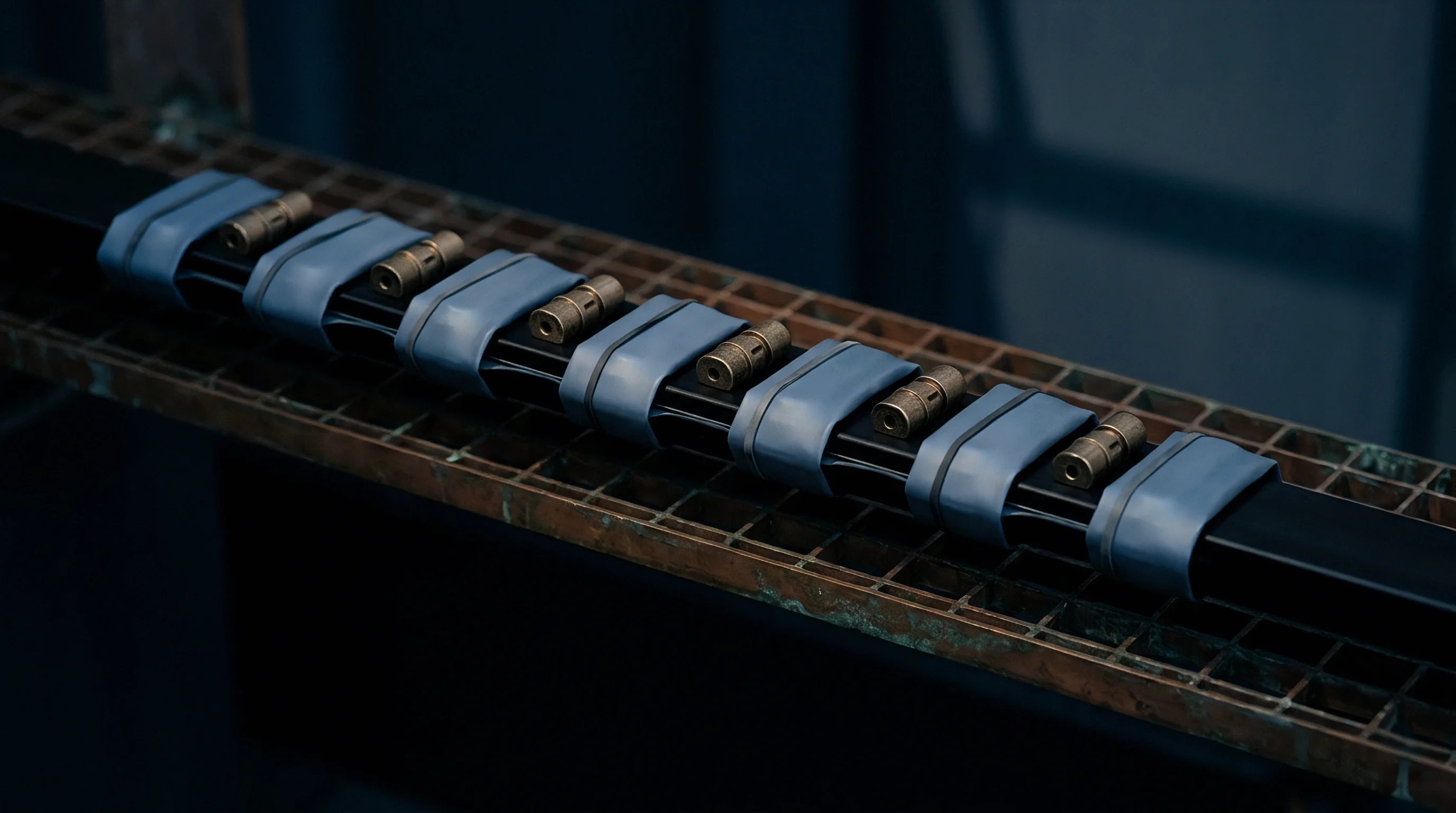
A 12-cell module stack exhibiting 9.6 millimeters of total life displacement requires a minimum foam allowance of 24.0 millimeters to avoid entering the densification zone above 40 percent compressive strain.
To keep pad strain below 40 percent at end-of-life fully charged conditions, total uncompressed pad thickness in the module must equal at least 2.5 times maximum anticipated linear displacement. Distributing this thickness across every cell interface spreads compliance evenly, preventing cumulative cell walking and terminal tab shear stresses during repetitive charging cycles.
Worked Sizing Calculation for Pouch Stacks
Assumptions for a worked mechanical sizing case:
Take a 12-cell series pouch module containing 65 Ah cells with a 10 weight percent silicon composite anode. Each fresh cell measures 10.50 mm plus or minus 0.15 mm nominal thickness at 30 percent state of charge. Active pouch face dimensions measure 280 mm width by 100 mm height, providing an active contact area of 28,000 square millimeters (0.028 m2).
Reversible breathing per cell equals 0.45 mm from zero to 100 percent state of charge. Irreversible thickness growth equals 0.55 mm per cell at the 1,000-cycle qualification limit. Total lifetime expansion per cell reaches 1.00 mm.
For 12 cells, cumulative lifetime stack expansion equals 12.0 mm. Sizing constraints limit maximum foam strain to 40 percent at end of life to avoid entering the steep densification curve. Required total uncompressed compliant foam thickness across the module equals 12.0 mm divided by 0.40, yielding 30.0 mm.
Distributing foam across 13 inter-cell and endplate positions requires individual uncompressed pad thicknesses of 2.31 mm. Standardizing to a commercial 2.50 mm nominal pad thickness yields 32.5 mm total compliant material.
At beginning-of-life discharged conditions, each 2.50 mm pad compresses by 0.50 mm (20 percent initial strain) to establish a baseline preload of 0.15 MPa (4,200 Newtons clamping force across 0.028 m2). At end-of-life charged conditions, additional 12.0 mm stack expansion compresses the total foam pack by another 12.0 mm, raising individual pad compression to 1.42 mm (56.8 percent strain). Standard polyurethane spikes into densification at 56 percent strain, generating over 2.2 MPa stack pressure and crushing separator membranes.
To prevent this spike, designers split compliance between 2.0 mm cell foam pads and metallic Belleville disc springs seated behind module endplates.
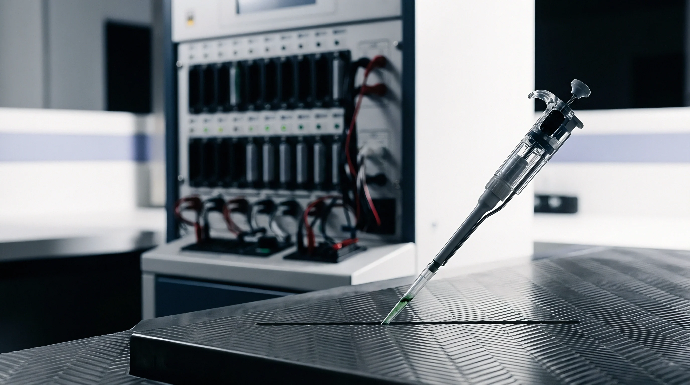
The assembly line applies this mechanical preload using an automated compression fixture that executes a defined kinematic sequence:
- The servo-electric ram compresses the alternating stack of cells and compliant pads to a designated force limit rather than a physical hard stop.
- The load cell monitors the reaction force until it stabilizes for three seconds, allowing transient viscoelastic air expulsion from the microcellular foam pores.
- The ram adjusts position to match the drawing nominal dimension, checking that the stabilized force sits within the verified tolerance window.
- The laser welding heads secure the structural side retention bands to the cast aluminum endplates while the ram holds the specified clamping displacement.
- The fixture releases external ram force, and secondary load cells verify that residual clamping force transferred into the tension bands meets baseline specification.
Clamping to fixed force absorbs component production thickness tolerances, while clamping to fixed dimensions controls module exterior mounting tolerances.

Fatigue
Module structural wrappers endure cyclic stress reversals over thousands of vehicle discharge and recharge cycles. Aluminum side plates, steel tension bands, and fastener threads act as dynamic springs coupled to the breathing cell stack. When cells expand, tension bands stretch in their elastic regime, absorbing part of the volumetric work while transmitting high tensile loads into endplate attachment welds or bolted joints.
Fast charging magnifies transient expansion. During high-rate charging (above 1.5C), lithium concentration gradients in the negative electrode peak sharply near the separator face, creating steep localized dilation waves before lithium ions diffuse evenly into bulk silicon particles. These transient dilation waves produce rapid strain spikes that subject structural module straps to high-cycle mechanical fatigue superimposed on low-cycle calendar breathing.
Could Wave Springs Mitigate End of Life Plasticity?
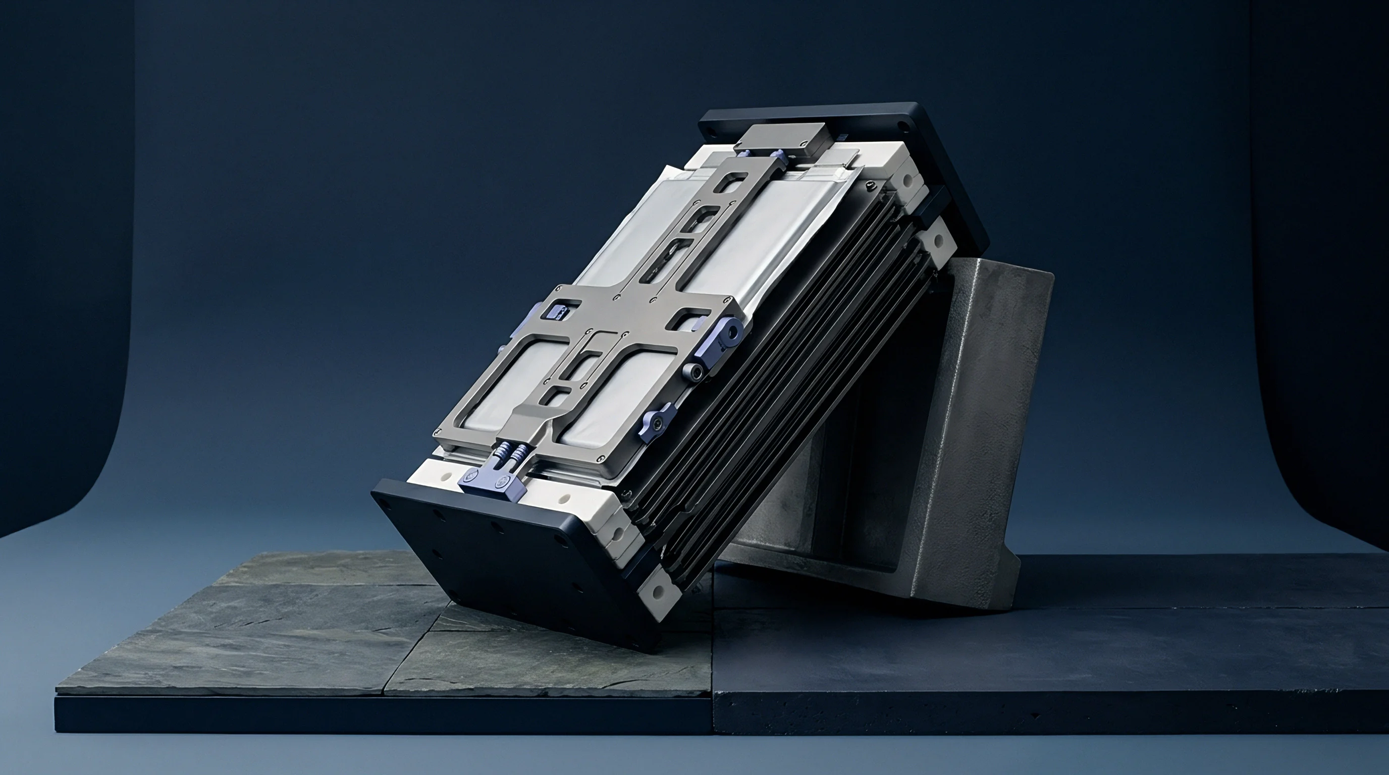
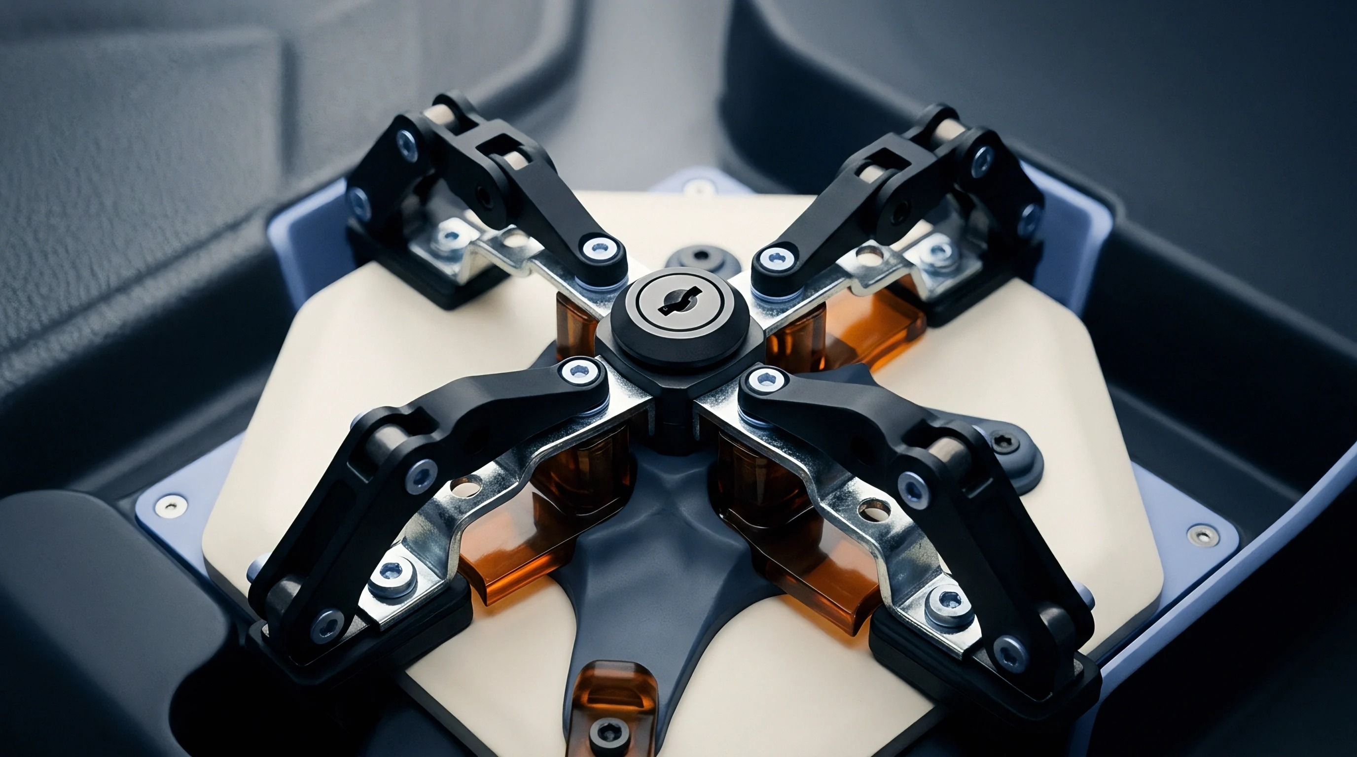
Metallic springs offer linear deflection characteristics and near-zero creep across the automotive operating temperature envelope. Integrating flat wave springs or stacks of Belleville disc springs behind the module endplate decouples compliant stroke from individual cell interfaces. A wave spring constructed from 17-7 PH stainless steel maintains its spring rate through millions of deflection cycles without the relaxation common to elastomeric pads.
Positioning Belleville washer packs to handle module compliance allows spring displacement to absorb irreversible swelling, while thin thermally conductive pads with zero compliance sit between cells to transfer heat efficiently into cooling plates. The metallic spring pack sits at the module end, deflecting linearly as the cell stack grows over years of cycling. The primary design challenge lies in spatial packaging: a Belleville spring stack capable of absorbing 12 mm of travel under a 6,000 Newton load requires substantial axial length, reducing volumetric packaging efficiency by 8 percent to 12 percent compared to distributed foam pads.
Under section 38.3.4.4 of the UN Manual of Tests and Criteria, retention hardware must withstand cyclic vibration profiles from 7 Hertz to 200 Hertz without loss of clamping torque or mechanical fatigue cracking of side bands.
Thermal Interface Shear under Dynamic Expansion
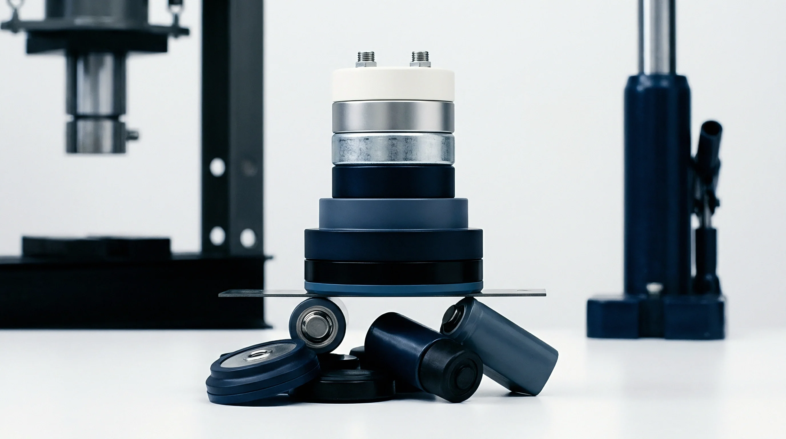
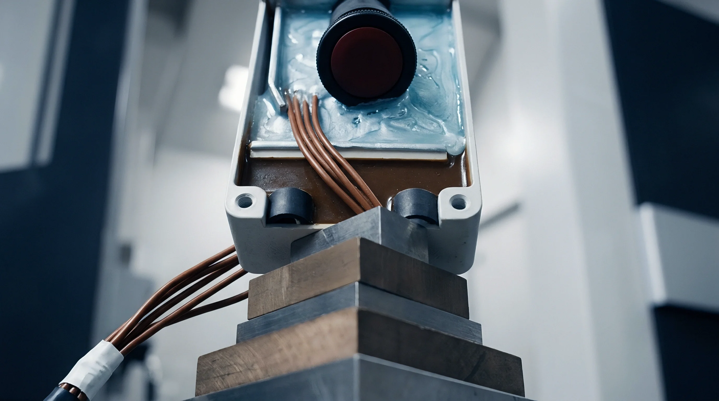
Cooling plates positioned beneath breathing modules introduce complex multi-axial shear loading at the bottom cell edge. Modules typically bond to liquid-cooled aluminum cold plates using structural thermal adhesives or compliant thermal interface material (TIM) pads. As cells cycle, their thickness changes along the horizontal stack axis, while the rigid bottom cooling plate stays dimensionally static.
Over 1,000 cycles, cumulative horizontal displacement of outer cells relative to the module center reaches 3 mm to 6 mm, creating shear displacement that destroys interfacial bonds. This cyclic sliding motion subjects the bottom thermal interface material to severe lap shear strain. Standard thermal adhesives crack and peel away from cell casing bottoms under repeated cycling, forming air gaps with thermal conductivities below 0.03 W/m·K. Once thermal contact breaks, cell operating temperatures diverge, creating thermal gradients across the module that accelerate degradation in uncooled cells.
Structural Band Yield and Fastener Relaxation
Tension bands wrapped around module endplates carry the full reactionary force of cell breathing. Designers specify either laser-welded austenitic stainless steel straps (such as 304 or 316 grade) or high-strength extruded aluminum alloys (such as 6000 series T6 temper). Austenitic stainless steel provides high ultimate tensile strength but exhibits lower elastic modulus and higher thermal expansion coefficients than carbon steels, causing preload variation across seasonal temperature swings.
Engineers evaluate structural retention integrity using a structured verification checklist:
- Tension Band Yield Margins evaluate that maximum tensile stresses at end-of-life full charge do not exceed 65 percent of the material yield strength (Rp0.2).
- Weld Seam Fatigue Strength verifies that laser stitch or butt welds joining side bands to endplates survive 3,000 cycles of mechanical fatigue loading.
- Threaded Fastener Engagement Ratios confirm minimum thread engagement lengths of 1.8 times bolt diameter when threading into cast aluminum end plates.
- Thermal Expansion Matching assesses thermal growth differentials between the cell stack and exterior steel bands across the minus 40 degrees Celsius to 85 degrees Celsius qualification envelope.
What remains unresolved across the industry is whether mechanical side straps can sustain unbonded friction interfaces against prismatic cell casings without fretting corrosion wearing through thin aluminum can walls during long-term operational vibration.

Underwriting
Commercial contracts and warranty documents hinge directly on the mechanical boundary conditions maintained by the module builder. Cell manufacturers producing high-energy silicon composite cells set strict pressure boundaries in their integration documentation. If incoming inspection or warranty teardown reveals that an integrator allowed stack pressure to drift outside these limits, the supplier rejects associated battery warranty claims.
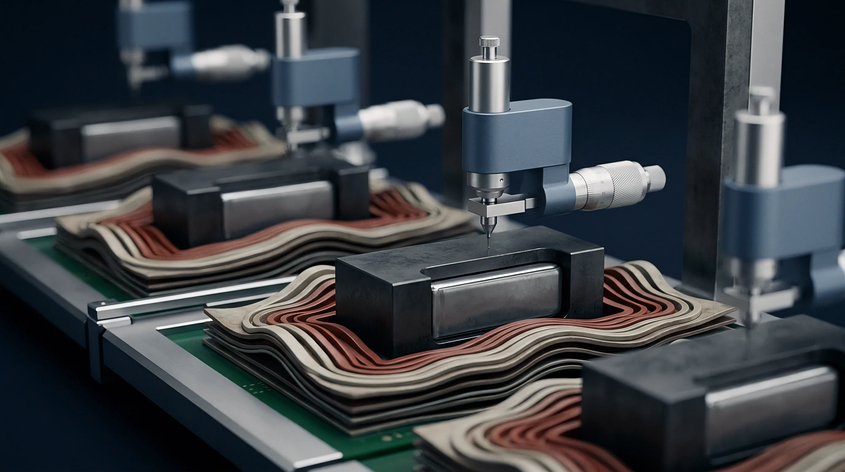
Cell warranties dissolve without physical evidence: when an automotive or stationary storage pack suffers premature capacity fade or cell degradation, determining whether root cause sits with cell electrochemical quality or pack mechanical design requires verifiable data. Sophisticated pack architectures integrate micro thin-film piezoresistive pressure sensors or strain-gauged side bands into production modules, recording real-time clamping stress history within the battery management system crash log.
Warranty Boundaries along the Pressure Corridor
Suppliers define acceptable cell operating windows through a pressure corridor specification. For a 10 weight percent silicon blend, a typical specification requires maintaining face pressure between a minimum of 0.10 MPa at beginning-of-life discharged state and a maximum of 0.80 MPa at end-of-life charged state. Operating below 0.08 MPa voids cycle life warranties due to particle isolation; operating above 1.20 MPa voids warranties due to separator pore collapse and lithium plating risks.
A cell manufacturer warranty file automatically disallows degradation claims when physical module disassembly reveals separator pore collapse indicative of excessive mechanical clamping.
Meeting this corridor across temperature variations from minus 30 degrees Celsius to 60 degrees Celsius demands tight tooling tolerances on module enclosures. A tolerance stack-up error of just 0.4 mm across a 12-cell module shifts baseline pressure by 0.25 MPa when using typical high-density microcellular foams, consuming over thirty percent of total allowable lifetime pressure margin before the pack ever leaves the factory floor.

Incoming Acceptance Sampling for Compliance Verification
Quality assurance teams verify compliance of incoming cell lots, compliant pads, and structural enclosures through documented inspection regimes prior to final assembly, as these records ultimately decide warranty disputes.
| Interface Boundary | Inspection Standard | Acceptance Criteria | Risk Allocation Ownership |
|---|---|---|---|
| Cell Nominal Thickness | ISO 2859-1 Level II Normal, AQL 0.4 | Thickness within plus or minus 0.12 mm at 30% SOC | Cell Supplier pays scrap and sorting labor |
| Compression Pad Modulus | ASTM D3574 Test C (CFD) | Force deflection curve within plus or minus 10% nominal | Pad Fabricator absorbs replacement tooling costs |
| Enclosure Cavity Dimensions | First Article CMM Scan, ASME Y14.5 | Total internal length within plus or minus 0.20 mm | Pack Integrator assumes machining rework expense |
| Post-Weld Preload Force | 100% In-Line Load Cell Verification | Preload force within plus or minus 5% target | Manufacturing Line Owner pays teardown costs |
Under Section 6.2 of standard cell supply supply agreements, the module builder warrants that structural enclosure deflection under maximum swelling force will not exceed 0.25 millimeters per hundred millimeters of span, transferring all mechanical containment liability to the integrator once the cell lot passes incoming thickness screening.