Designing Module Compression Frames for Anisotropic Solid Anode Expansion
Designing solid-state module frames requires compliant pads and rigid end straps that hold cell face pressure between 0.5 and 3.5 MPa across all operating cycles.
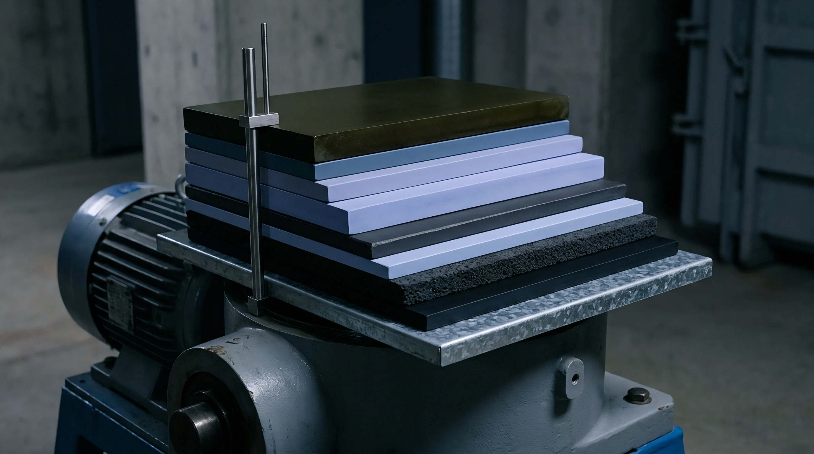
Swell
Solid-state pouch cells employing lithium metal or high-ratio silicon anodes concentrate volumetric expansion along the stack thickness axis. Microscopic crystallographic changes during charge force active material outward, yet lateral mechanical constraint from current collector foils and separator friction channels over ninety-eight percent of this displacement into the perpendicular z-axis. Standard lithium-ion graphite anodes expand between four and seven percent during lithiation.
Silicon composite electrodes expand beyond twenty-five percent at fifty percent state of charge, while pure lithium metal anodes plate continuously, creating an interface displacement of approximately 2.06 micrometers per milliampere-hour per square centimeter of areal capacity. Silicon undergoes extreme lattice dilation. Stripping leaves microscopic interfacial voids.
Contact resistance rises rapidly.
Designing an operational module enclosure hinges on separating cyclical state-of-charge breathing from irreversible state-of-health thickness growth. Cyclical breathing occurs as lithium ions intercalate into host materials or plate onto the negative substrate during charge, reversing completely upon discharge. Irreversible thickness growth accumulates across hundreds of duty cycles through dead lithium accumulation, electrolyte breakdown, solid electrolyte interphase creep, and mechanical micro-cracking of brittle solid separator membranes.
In a typical twenty-four-cell pouch series, reversible breathing displaces between 2.5 and 4.0 millimeters across the complete stack, while end-of-life permanent growth adds another 3.5 to 6.0 millimeters depending on ambient operational temperature and discharge depth.
Lithium metal pouch cells cycled at 1.0 C under 0.8 MPa stack pressure lose thirty percent of active contact area once retention force drops below 0.25 MPa during discharge.
Mechanical pressure maintains physical contact between the deformable lithium or silicon anode and the rigid solid electrolyte separator. Solid ceramic or sulfide separators, such as lithium lanthanum zirconium oxide or lithium phosphorus sulfur chloride, lack the liquid wetting action of conventional non-aqueous electrolytes. Lowering interfacial pressure below 0.3 megapascals permits void formation during high-rate stripping, concentrating current density at remaining contact points and accelerating dendrite propagation.
Exceeding 5.0 megapascals crushes micro-porous structures, fractures brittle ceramic sheets, and extrudes metallic lithium past edge margins. Cell manufacturers cite this narrow operational pressure band in warranty literature, yet factory sales representatives consistently claim that upcoming material batches will resolve late-life thickness divergence without heavier pack hardware.
Crystallographic Strain and Macroscopic Face Growth
Intercalation processes distort active crystalline lattices at predictable geometric ratios. Alloying silicon with lithium to form the fully lithiated phase causes theoretical lattice volume increases exceeding two hundred and eighty percent. Even when blended into carbon scaffolds at fifteen weight percent, the composite electrode layer swells thirty percent macroscopically during charging.
Lithium metal anodes exhibit unconstrained planar deposition where thickness tracks transferred charge directly. A cell operating at an areal capacity of four milliampere-hours per square centimeter deposits an eight-micrometer film of fresh lithium metal on every full charge cycle. Without dynamic mechanical constraint, this plated layer grows unevenly, forming porous, mossy structures that trap dead metal and degrade Coulombic efficiency below ninety-nine percent within two hundred cycles.
Reversible Breathing versus Irreversible Grid Deformation
Differentiating dynamic operational displacement from permanent component deformation governs structural sizing. Dynamic breathing tracks state-of-charge maps precisely, expanding linearly from zero to one hundred percent charge and contracting during discharge. Irreversible growth follows an exponential curve during early formatting cycles, stabilizing into a linear slope during regular cycling before entering a tertiary acceleration phase as mechanical damage accumulates.
Cell testing protocols reveal that cells cycled under three megapascals maintain planar uniformity but experience accelerated solid electrolyte pulverization. Conversely, testing at 0.1 megapascals preserves separator integrity while allowing delamination voids to halve cell capacity within four hundred cycles. Sourcing contracts define warranty thresholds using these exact cycle-life degradation curves, forcing pack architects to construct containment structures that accommodate both displacement regimes without yielding.
Platen
Interfacing bare pouch pouches with rigid structural enclosures demands mechanical compliance that absorbs breathing without exceeding interfacial stress limits. Direct cell-to-cell contact without intervening compliant material generates localized pressure peaks during charge cycles. Pouch cell surfaces possess intrinsic thickness variations, typically measuring twenty to fifty micrometers thicker along perimeter heat-seal margins than at stack centerlines.
Clamping these cells between parallel plates without elastomeric cushioning concentrates compressive loads along cell edges, rupturing internal ceramic separators along electrode boundaries. Separator puncture causes thermal catastrophe.
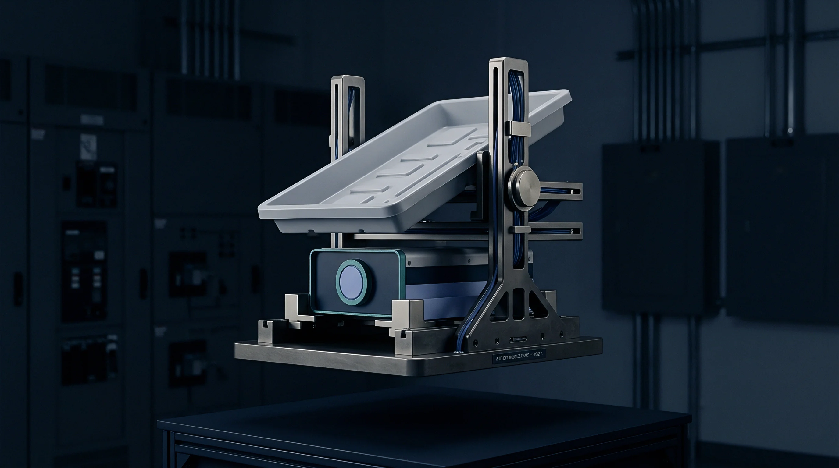
Elastomeric foam pads positioned between individual cells distribute clamping forces evenly across the active electrode area. Materials such as microcellular polyurethane and closed-cell silicone foam function as internal non-linear springs. As cells expand during charge, the elastomeric pads compress, absorbing the physical displacement while allowing stack pressure to rise within controlled limits.
Microcellular polyurethane delivers high initial damping and steep progressive stiffness curves, but exhibits measurable compression set and thermal softening when operating above forty-five degrees Celsius. Polyurethane relaxes under elevated temperatures. Silicone foams deliver inferior mechanical damping but maintain consistent spring rates from minus forty to one hundred and twenty degrees Celsius, exhibiting minimal compression set across ten-year design horizons.
Silicon foams resist continuous heat.
Inter-cell elastomeric pads experience irreversible compression set exceeding fifteen percent after three years of sustained thermal exposure.
Quantifying pad performance involves plotting stress against strain across anticipated operational temperatures. Compression force deflection curves determine the operating pressure window. When a module uses twelve-cell groups, total breathing displacement reaches several millimeters.
The selected elastomer must maintain at least 0.4 megapascals of restorative force when the cell stack contracts to its minimum thickness at zero percent state of charge at minus twenty degrees Celsius, while restricting maximum pressure to less than 3.5 megapascals when the stack expands to one hundred percent state of charge at end of life at fifty degrees Celsius. Sizing this compliant layer requires balancing foam thickness against volumetric pack energy density, since every additional millimeter of silicone foam reduces active cell volume.
Elastic Media Selection and Creep Dynamics
Material creep undermines long-term mechanical pressure stability. Under sustained compressive loading inside an automotive module, elastomeric polymers undergo molecular relaxation, shedding restorative force over extended periods. Accelerated aging trials indicate that microcellular polyurethane loses between twelve and twenty-two percent of its initial clamping force within two thousand thermal-mechanical cycles.
Silicone foam formulations demonstrate superior creep resistance, shedding between six and nine percent under equivalent mechanical exposure. The desk cannot fully defend published five-year creep models for newly commercialized fluorosilicone blends, as empirical aging data under combined electrolyte vapor exposure and dynamic cyclic loading remains scarce across the industry. Integrators mitigate this data gap by oversizing initial pad thickness by fifteen percent relative to nominal displacement calculations.
| Material Formulation | Nominal Density (kg/m³) | Compression Set at 70°C (%) | Usable Strain Range (%) | Stiffness Retention at 1000 Cycles (%) | Thermal Conductivity (W/m·K) |
|---|---|---|---|---|---|
| Microcellular Polyurethane | 320 | 14.2 | 10 to 45 | 78.5 | 0.09 |
| Closed-Cell Silicone Foam | 400 | 4.8 | 15 to 50 | 92.1 | 0.14 |
| Fluorosilicone Elastomer | 550 | 3.2 | 10 to 40 | 94.6 | 0.18 |
| Crosslinked Polyethylene | 120 | 28.5 | 5 to 30 | 62.0 | 0.04 |

Where Does Frame Deflection Induce Shorting?
Platen flexibility causes uneven pressure distribution that directly precipitates separator fracture. When end pressure platens bow under central expansion loads, compression shifts entirely toward module perimeter tie-rods. Center cells experience reduced pressure.
This pressure loss allows lithium dendrites to push through solid electrolytes at the stack center, while cell corners endure extreme localized stress concentrations. Edge stress cracks pouch pouches. Shearing forces along the active material boundary tear the heat-sealed packaging foil, venting trace gases and allowing moisture ingress that reacts with sulfide-based solid electrolytes to generate toxic hydrogen sulfide gas.
Pads specified solely from room-temperature initial compression curves collapse under combined thermal elevation and cyclic mechanical strain.

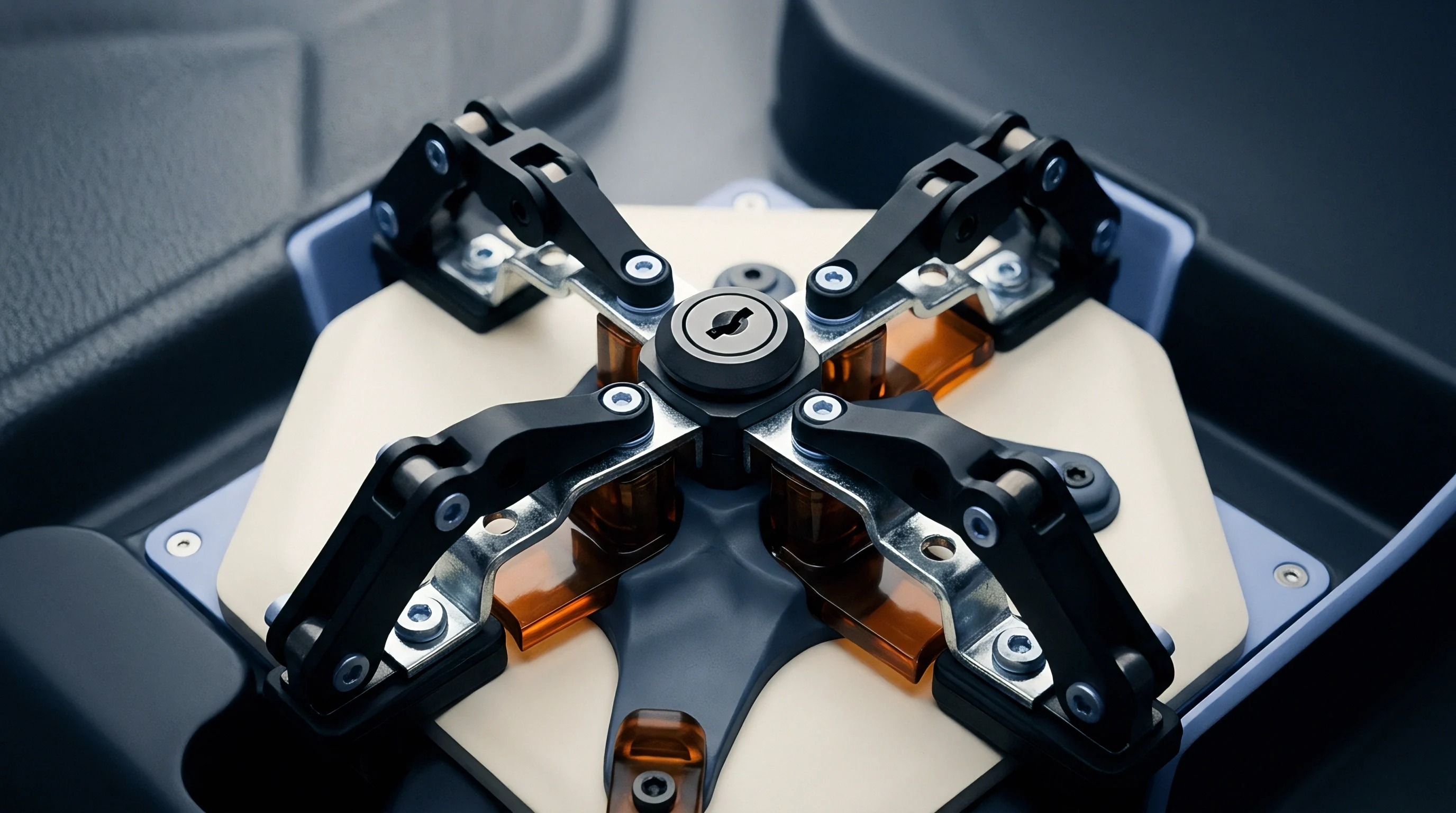
Tie
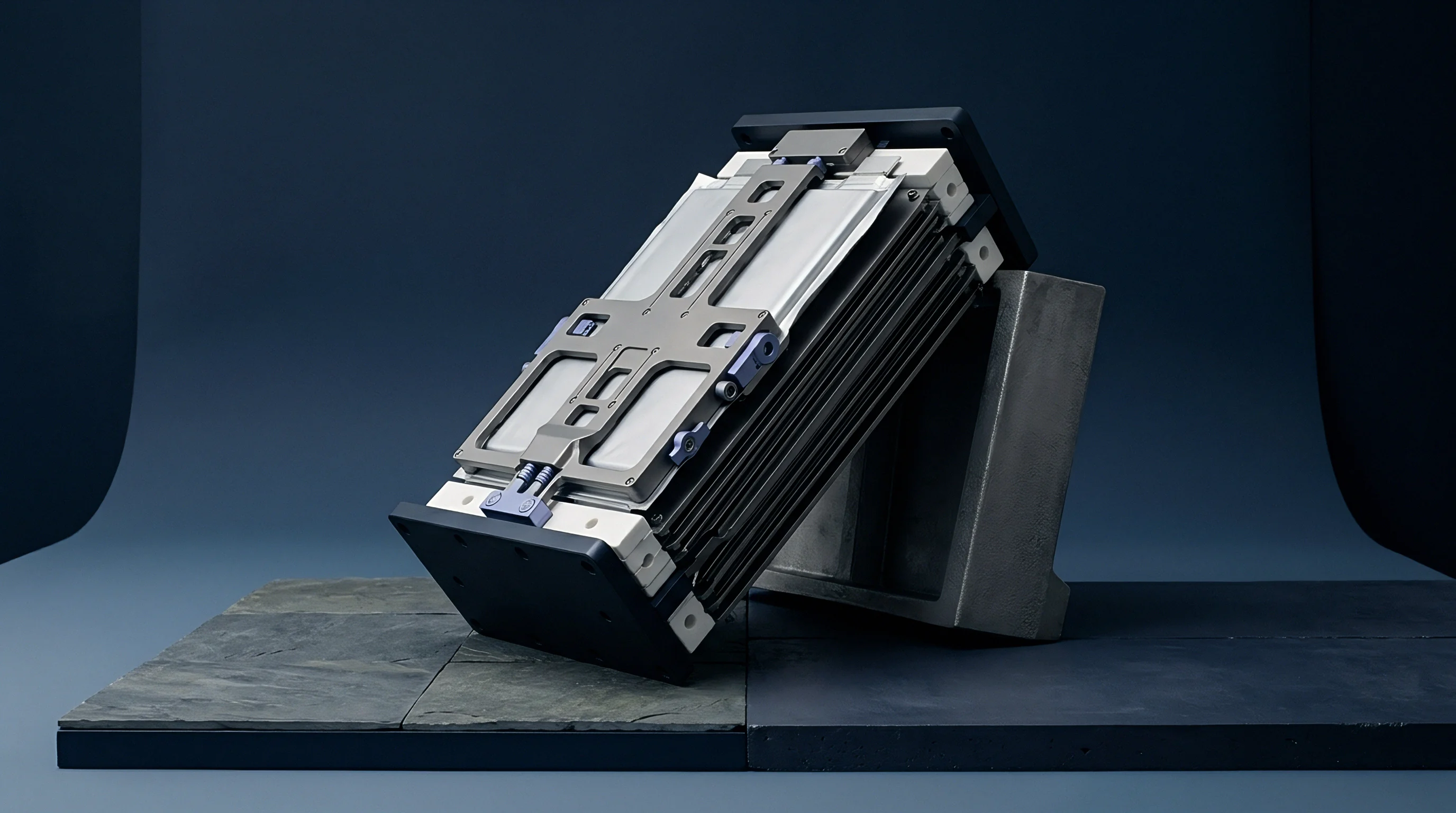
Structural containment assemblies balance tensile strap stiffness against the mass budget of vehicle chassis integration. External module structures hold the cell stack under continuous compressive load, counteracting hundreds of kilonewtons of cumulative expansion force over the pack operating lifespan. End plates bow under load.
A module containing twenty-four solid-state pouch cells with an active face area of fifteen thousand square millimeters generates fifteen kilonewtons of internal thrust at a modest stack pressure of one megapascal. At end-of-life peak charge, this force can easily exceed forty-five kilonewtons. The containment framework must withstand these loads without exceeding elastic deformation limits, as plastic elongation in tie-rods or side straps destroys module preload.
Structural configurations divide into two primary archetypes: rigid end plates connected by continuous tensile side bands, or cast end bulkheads secured with high-tensile threaded tie-rods. Welded stainless steel side bands provide superior volumetric efficiency, wrapping tightly around aluminum end platens to create a compact, light frame. Threaded tie-rods introduce assembly flexibility, allowing automated torque tools to dial in precise initial preload forces on the factory floor, though they add significant perimeter mass and require anti-vibration locking mechanisms to survive field vibration profiles.
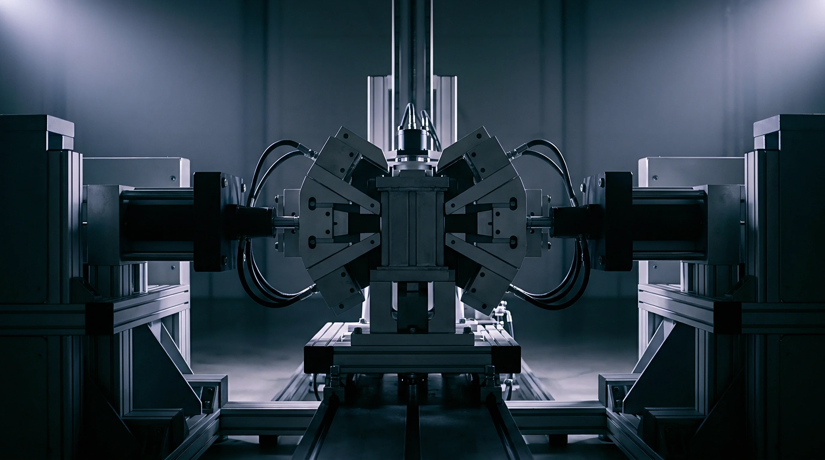
Similar structural challenges exist in high-pressure hydraulic autoclave presses, where multi-axis platen deflection must stay strictly within sub-millimeter tolerances across cyclic thermal exposures to prevent composite part distortion.
Finite element models confirm that end plate centerlines deflecting more than 0.2 millimeters induce a forty percent pressure drop at the core of adjacent solid-state cells.
Evaluating tie-rod versus tension-band mechanics demands precise calculations of structural elongation under dynamic thermal-mechanical cycles. Welded straps yield under cyclic fatigue. Stainless steel grade 304 tension bands exhibit an elastic modulus of one hundred and ninety-three gigapascals, elongating under cyclic loads and shifting the cell stack operating pressure downward over time.
Aluminum side rails save weight but suffer from high thermal expansion coefficients, expanding at 23.1 micrometers per meter-Kelvin, which causes module clamping pressure to drop substantially during cold-weather storage and surge during elevated summer operations.

End Plate Deflection and Centerline Bowing
Bending moments across structural end plates dictate the planar uniformity of interfacial stack pressure. End plates behave as uniformly loaded beams supported at their outer edges by side bands or tension bolts. Under twenty-five kilonewtons of central thrust, a flat fifteen-millimeter aluminum plate exhibits parabolic deflection across its face.
Reinforcing end plates with external stiffening ribs, or designing them with an inward parabolic crown prior to assembly, neutralizes this deflection under nominal load. Progressive stamping or die casting enables production lines to incorporate structural ribbing without adding dead mass, ensuring that platen contact faces remain parallel within fifty micrometers under full end-of-life swelling force.
| Frame Configuration | Material Specification | Total Frame Mass (kg) | Centerline Deflection (mm) | Peak Strap Tensile Stress (MPa) | Assembly Line Takt (s) |
|---|---|---|---|---|---|
| Flat End Plates with 4 Tie-Rods | Al 6061-T6 Platens, Steel 4140 Rods | 4.85 | 0.38 | 210 | 68 |
| Ribbed Die-Cast with Welded Straps | Al A380 Platens, 304 Stainless Straps | 3.10 | 0.08 | 340 | 32 |
| Crowned Platens with Laser-Welded Side Plates | Al 7075-T6 Platens, Al 6082-T6 Plates | 2.65 | 0.11 | 185 | 45 |
| Forged Magnesium with Carbon Fiber Straps | AZ80A Platens, Toray T700 Composite | 1.75 | 0.06 | 410 | 110 |
Worked Calculation for a Twenty-Four Cell Module
Take an operational module assembly containing twenty-four series-connected solid-state pouch cells. Assume each cell measures two hundred millimeters in width, one hundred and fifty millimeters in height, and five millimeters in initial uncompressed thickness. Active electrode area measures twenty-seven thousand square millimeters per cell.
The target mechanical interface demands an initial baseline pressure of 0.8 megapascals at twenty percent state of charge, rising to a maximum allowable limit of 2.5 megapascals at one hundred percent state of charge under end-of-life conditions. Nominal initial clamping force requires twenty-one point six kilonewtons across the platen face.
Reversible breathing accounts for an eight percent thickness fluctuation per cell, translating to 0.40 millimeters per cell or 9.60 millimeters of dynamic displacement across the twenty-four-cell stack. Irreversible end-of-life growth adds another twelve percent permanent expansion, adding 0.60 millimeters per cell or 14.40 millimeters across the stack. Total cumulative stroke reaches twenty-four millimeters.
Integrating twenty-five compliant silicone foam pads of two-millimeter thickness adds fifty millimeters of uncompressed elastomer to the internal stack length. Sizing two grade 304 stainless steel side straps to carry the resulting peak compressive load of 67.5 kilonewtons demands an aggregate cross-sectional steel area of at least one hundred and thirty-five square millimeters to maintain tensile working stresses below five hundred megapascals, well beneath the material yield strength. Each strap must measure two millimeters in thickness and thirty-five millimeters in width.
Structural analysis based on these dimensions confirms strap elongation under peak force remains below 0.35 millimeters over an active span of one hundred and seventy millimeters, preserving interfacial pressure containment.
Failure modes in containment framing propagate through distinct structural pathways:
- Fastener thread stripping occurs when tightening torque on tie-rod nuts exceeds female thread shear limits during automated high-speed line assembly.
- Side strap weld fatigue develops under repetitive state-of-charge breathing cycles, initiating micro-cracks at laser-weld termination points that propagate across the structural band.
- End plate bowing reduces interfacial contact pressure across cell centers, creating uneven current density profiles and localized thermal hotspots during rapid charge cycles.
- Elastomer extrusion forces compliant pad margins past cell perimeter boundaries, leaving raw pouch edges vulnerable to direct mechanical contact with metallic framework components.
Specifying under-gauged end plates concentrates interfacial pressure along cell perimeters, crushing separator margins and triggering premature thermal runaway during fast charging.

Stack
Dimensional tolerance accumulation across manufacturing lots dictates the initial mechanical setup of production compression fixtures. Incoming cell pouches exhibit unavoidable geometric variation resulting from cathode coating variations, current collector foil thickness tolerances, separator consistency, and vacuum pouch packaging folds. A single cell carries a thickness tolerance of plus or minus 0.08 millimeters.
Cell dimensions vary across production batches. Summing these variations across a twenty-four-cell module stack yields a worst-case dimensional divergence of plus or minus 1.92 millimeters, alongside a statistical root-sum-square variation of plus or minus 0.39 millimeters. Failure to normalize this stackup results in massive variations in baseline assembly pressure.
Precision shimming programs normalize mechanical variations before permanent frame securement. Measuring the uncompressed cell stack under a light calibration load of 0.05 megapascals establishes the exact physical baseline of each unique cell group. Automated assembly cells calculate the deviation from nominal length, selecting graded steel or composite shims in increments of 0.1 millimeters to place between the end platen and the cell face.
Shims compensate for manufacturing stackup. This shimming operation brings initial preload forces within a tight five percent tolerance band, ensuring every manufactured module enters service with uniform electrochemical conditions.
Selective shimming of incoming cell stacks narrows initial clamping force variation from forty-five percent down to four percent across high-volume assembly lines.
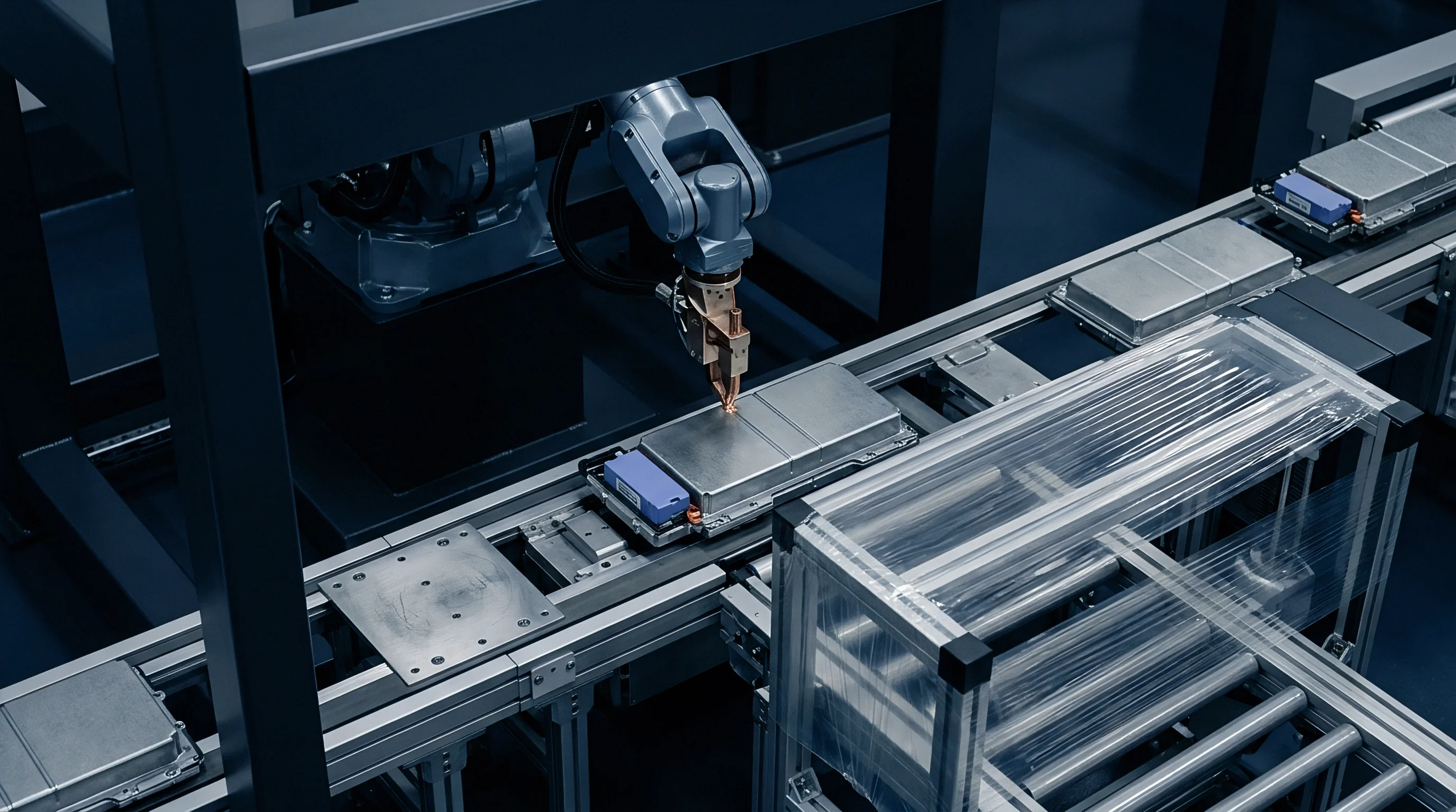
Factory automation equipment handles this process using multi-axis servo-electric presses outfitted with continuous load-cell feedback. Defective pouches expand prematurely. Press routines operating purely on position control generate dangerous force spikes when pressing oversized cell stacks, crushing solid-state separators before the module leaves the factory.
Force-controlled press routines compress the stack to a calibrated target force, holding that mechanical load while automated fiber-laser welding systems join the tension straps to the end platens. This sequence locks in the exact specified preload regardless of minor component variations.

Statistical Stackup and Shimming Strategy
Managing manufacturing tolerances requires strict categorization of incoming component lots. Module assembly lines implement statistical process control gates that grade cell lots by physical thickness alongside electrical capacity. Grouping cells of matched thickness reduces intra-module variance, minimizing the thickness of required shims.
The following table illustrates the tolerance budget and required shimming categories across typical production variations.
| Tolerance Parameter | Component Deviation (mm) | Stack Deviation (mm) | Statistical RSS Deviation (mm) | Corrective Shim Range (mm) |
|---|---|---|---|---|
| Pouch Thickness Variation | ±0.08 | ±1.92 | ±0.39 | 0.2 to 2.0 |
| Compliant Pad Thickness | ±0.12 | ±3.00 | ±0.60 | 0.5 to 3.5 |
| End Platen Machining | ±0.05 | ±0.10 | ±0.07 | 0.1 to 0.3 |
| Strap Length Tolerance | ±0.15 | ±0.15 | ±0.15 | 0.1 to 0.4 |
| Values reflect three-sigma manufacturing capabilities for automotive-grade cell and module components. | ||||
What Clamp Pressure Preserves Pouch Seals?
Mechanical pressure on active electrode faces must never bleed into the perimeter hermetic pouch seals. Heat-sealed polymer-aluminum margins secure volatile electrolyte components and isolate internal active chemistry from ambient air. Applying uncontrolled compressive loads across these seals causes polymer creep, thinning the sealing layer and inducing catastrophic micro-leaks.
Module designers isolate seal areas by machining perimeter relief grooves into end platens and inter-cell compression pads, maintaining zero direct clamping force across the outer six millimeters of the pouch perimeter.
Production facilities execute module assembly using a rigid procedural sequence:
- Stack twenty-four graded solid-state pouch cells interleaved with twenty-five pre-conditioned silicone compliant foam pads within an automated alignment fixture.
- Advance the servo-electric press ram under position control at fifty millimeters per second until reaching the initial contact threshold of fifty newtons.
- Switch ram control to closed-loop force mode, ramping axial load to twenty-one point six kilonewtons at a controlled rate of five hundred newtons per second.
- Measure total compressed stack length with optical laser micrometers to determine deviation from nominal design specifications.
- Insert selected precision gauge shims between the terminal cell insulator and the inner face of the structural end platen to neutralize measured deviation.
- Fire dual fiber-laser weld heads simultaneously to fuse the grade 304 stainless steel side tension bands to the aluminum end platens under active force control.
- Release press ram, transfer module to the automated diagnostic station, and record baseline module open-circuit voltage and internal resistance.
Incoming inspection procedures verify cell quality through specific physical gates:
- Acoustic scanning microscopy detects internal delamination voids between solid electrolyte layers and active material matrices prior to mechanical preloading.
- Optical laser profilometry maps uncompressed cell surface topology to confirm that thickness variations across active faces remain within thirty-five micrometers.
- High-potential isolation testing validates electrical insulation resistance between pouch sealing tabs and external casing foil under five hundred volts direct current.
- Thermal imaging under pulse discharge reveals localized current concentrations indicative of micro-defects within internal ceramic separator coatings.
Force-controlled press engagement prevents the cumulative tolerance envelope from crushing individual cell margins during module banding.
Automated servo-press systems log the exact displacement and force vector for every serialized module, establishing a baseline record for subsequent warranty analysis.

Warranty
Commercial agreements governing solid-state modules establish clear dividing lines between electrochemical degradation and mechanical containment liability. When a module loses capacity prematurely, dispute immediately centers on whether the cell chemistry degraded autonomously or the module frame failed to maintain specified interfacial compression pressure. If an external tension strap yields, stack pressure drops, causing void formation, interfacial impedance spikes, and severe capacity loss.
Conversely, if cell active material swells beyond contracted limits, the resulting pressure surge crushes solid electrolytes and ruptures pouch casings. Excessive expansion voids manufacturer guarantees.
Integrating mechanical pressure telemetry into battery management systems resolves this diagnostic impasse. Modern module designs incorporate thin-film piezoresistive pressure sensors or strain gauges applied directly to structural side straps. Piezoresistive films map pressure distribution.
Sourcing contracts explicitly define operational envelopes based on this sensor data. If the module management system records strap strain indicating stack pressure fell below 0.3 megapascals while the vehicle operated under load, the warranty seam assigns financial liability to the module pack packager for structural failure. If telemetry proves the frame maintained specified pressure while cells experienced rapid capacity fade, commercial responsibility falls squarely on the cell manufacturer.
Standard master supply agreements designate cell swelling exceeding twelve percent prior to eight hundred equivalent full cycles as an electrochemical defect that voids pack structural liabilities.
Compliance certification introduces further engineering constraints under international transportation standards. United Nations standard UN 38.3 mandates severe vibration, mechanical shock, and impact testing on completed module structures. Clamping large cell stacks under forty kilonewtons of continuous force shifts the natural resonant frequency of the assembly into higher harmonic registers.
Vibration profiles that pass easily on conventional uncompressed lithium-ion modules can shear stressed tie-rods or fracture brittle solid-state ceramic separators within preloaded modules. Securing transport certification demands rigorous finite element modal analysis to ensure module natural frequencies avoid vehicle suspension excitation bands between ten and fifty hertz.
BMS Sensor Telemetry and Pressure Tracking
Integrating continuous load monitoring transforms static battery management into active structural health monitoring. Piezoresistive sensor arrays positioned at stack centerlines output analog voltage signals proportional to interface pressure. The battery management system samples these channels at low frequency, logging daily maximum and minimum pressure vectors to non-volatile memory alongside cell temperature and voltage data.
This empirical record eliminates post-failure ambiguity, providing both cell supplier and pack integrator with transparent operating histories when adjudicating field warranty returns.

Allocation of Degradation and Structural Faults
Contractual risk allocation requires clear definitions in Master Supply Agreements. Legal terms separate root causes into quantifiable physical metrics: strap elongation, end plate fatigue, pad compression set, and chemical thickness growth. When mechanical frames yield under forces below the contracted threshold, pack integrators shoulder total module replacement costs.
However, when cell swelling exceeds contracted limits, cell vendors absorb both module replacement and field recall expenses.
Standard supply exhibits assign structural containment fatigue claims entirely to the system integrator unless module telemetry demonstrates continuous cell breathing forces beyond the agreed envelope.