First Article Inspection Protocols for Custom Pack Stamping Dies
First article approval for pack stamping dies requires free-state optical scanning coupled with micro-sectioned edge burr verification below 0.03 mm.
Steel
Selecting forming tool alloys for sheet metal components requires balancing compressive yield strength against adhesive wear resistance. Stamped structural enclosures, cooling trays, crossmembers, and high-current copper busbars impose distinctly different loads on die surfaces. Aluminum sheet ~ notably work-hardened 5000-series and heat-treatable 6000-series alloys ~ tends to gall against tool steel substrates.
During cold forming, localized micro-welding transfers aluminum onto punch radii and die cavities, creating raised galling peaks that score subsequent panels. Die engineering relies on matching alloy chemistries, heat treatment cycles, and surface coatings to survive continuous press cycles without chipped cutting edges or dimensional drift.
Substrate selection dictates tool longevity, maintenance intervals, and dimensional repeatability over high-volume runs. Standard AISI D2 tool steel provides adequate compressive strength for short stamping runs, but its coarse carbide network is prone to chipping along tight draw radii in work-hardened aluminum. DC53 cold-work die steel features a finer, more uniform carbide distribution that yields roughly twice the toughness of D2 while holding a working hardness of 60 to 62 HRC.
For abrasive cuts or thick copper busbars, high-wear piercing punches and trim dies use powder metallurgy grades such as Vanadis 4 Extra to maintain edge integrity. Solid tungsten carbide inserts placed in high-stress stations further protect punches from premature fatigue failure.
Tooling Alloy Selection for Structural Battery Enclosure Dies
Cold-work tooling materials endure intense mechanical shock when forming high-volume structural battery trays. Substrate selection determines whether deep-drawn housings and heavy-gauge perimeter channels stay within drawing tolerances over time. Working die components must resist multi-axial impact, continuous sliding friction, and high shear loads without plastic deformation.
Final alloy selection depends on the specific forming or cutting operation assigned to each station in a progressive or transfer press.
Primary forming components undergo vacuum heat treatment followed by multi-stage cryogenic tempering. Sub-zero cooling at minus 180 degrees Celsius converts retained austenite to martensite, improving dimensional stability and wear resistance under load. PVD or Thermal Diffusion (TD) coatings isolate the steel substrate to stop adhesive metal transfer.
TD-applied vanadium carbide layers exceed 3000 HV in hardness, preventing aluminum pickup on severe draw radii. For dry or minimum quantity lubrication (MQL) lines, PVD coatings such as Titanium Aluminum Nitride (TiAlN) and Chromium Nitride (CrN) provide low-friction working barriers.
Progressive die wear gradually alters the springback behavior of formed components.
| Tool Material | Hardness Range | Surface Treatment | Target Stamping Application | Tooling Wear Mechanism |
|---|---|---|---|---|
| AISI D2 Cold-Work Steel | 58 to 60 HRC | Uncoated / Nitrided | Low-volume tray top covers, basic mounting brackets | Adhesive galling, edge chipping on sharp bend radii |
| DC53 Cold-Work Alloy | 60 to 62 HRC | PVD CrN or TiAlN | Structural side rails, module retainers, crossmembers | Mild abrasive wear, localized material pickup |
| Vanadis 4 Extra (PM) | 60 to 64 HRC | PVD Diamond-Like Carbon | High-speed progressive blanking, busbar piercing punches | Micro-chipping under cyclic punch impact |
| TD-Treated Tool Steel | 62 to 64 HRC Substrate | Thermal Diffusion Vanadium Carbide | Deep-drawn aluminum cooling trays, structural channels | Coating delamination under extreme contact pressure |
| Tungsten Carbide (12% Co) | 88 to 90 HRA | Polished Mirror Finish | Precision busbar fine-blanking dies, high-takt copper punches | Brittle fracture under tool tilt or offset clearance |
| Substrate selection criteria assume dry or MQL lubricant application across 5000-series aluminum and C11000 copper sheet stock. | ||||
Punch Clearances and Press Tonnage Dynamics
Cutting clearance dictates shearing tonnage requirements and burr formation during progressive blanking. Recommended punch-to-die clearances range between six percent and twelve percent of total material thickness t per side, calibrated to the tensile strength and elongation of the stock. Ductile aluminum grades require tight clearances ~ typically six percent to eight percent of sheet thickness ~ to limit edge rollover and produce a clean shear cut.
Insufficient clearance spikes required blanking force, accelerates punch wear, and produces secondary shear bands. Excessive clearance rounds the burnish zone, throwing tall burrs and deep rollover pockets along the cut edge.
Press capacity and frame stiffness govern part consistency during sustained runs. Press beds deflect under tonnage, shifting dynamic punch alignment relative to lower die stations. Dynamic shut-height variation under load must stay within +/- 0.01 mm across the bed to avoid uneven bottoming in form stations.
During deep drawing, hydraulic cushions regulate material flow, maintaining uniform blankholder pressure to prevent wrinkling and wall tears. Stroke-by-stroke load monitors track tonnage signatures to flag off-center loading caused by unbalanced progressive tooling.
Fluctuations in available press tonnage directly affect final draw depths.
Substrate Springback Mechanics in Aluminum Pack Trays
Elastic recovery in cold-formed sheet pulls stamped panels away from nominal CAD geometry. High-strength alloys like 6061-T6 and 5754-H111 exhibit substantial springback after bending or stretch forming. The yield-to-tensile strength ratio governs the scale of this recovery, which is why T6 tempers rebound considerably more than annealed stock.
Die cavities must incorporate compensation via over-bent radii, localized strain-hardening beads, or bottoming strikes that coin the bend line to set material memory.
Planar anisotropy and crystallographic rolling texture cause springback to vary across stamped tray panels. Sheet yield stress and plastic strain ratios (r-values) shift depending on whether a bend runs parallel, transverse, or at 45 degrees to the coil rolling direction. Aligning critical structural bends relative to the coil axis reduces angular deviation between parts.
First-article die trials assess raw material variability by testing sample coils drawn from the lower, middle, and upper limits of the mill yield-strength window.
Crystallographic anisotropy across the sheet causes uneven flange heights.
Failure mechanisms during initial press trials reveal specific physical defects caused by improper clearance, material variation, or unbalanced die forces.
- Adhesive Galling Accumulation Aluminum transferring onto uncoated punch radii changes forming geometry and scores structural tray side walls.
- Edge Burr Shear Protrusion Excessive punch clearance leaves sharp metal protrusions along cut edges that pierce dielectric insulation layers during pack assembly.
- Corner Flange Wrinkling Low blankholder clamping pressure lets compressive stress buckle thin metal in deep-drawn corner radii.
- Radius Fracture Split Tight punch radii that exceed material elongation limits cause micro-cracking and full tensile splits along primary structural bend axes.
- Oil-Canning Deflection Strain Residual internal stress and unbalanced stretch zones across broad flat floors create bistable buckling.
Punch-to-die clearance held at 8 percent of stock thickness limits edge burr height below 0.03 mm across 5000-series aluminum stampings.
Forming simulations provide an initial die surface, but springback correction still requires manual fitting on the shop floor. Toolmakers stone coining inserts and adjust pad pressures during tryout to deliver flat mounting interfaces for cooling plates and module retainers. First-article inspections then verify that these adjustments maintain tolerance across operating stroke speeds and press temperatures.
Designing bottoming pads with proper radius compensation keeps springback variations between metal heat lots from stopping the line.

Gage
A coordinate measurement strategy determines whether a stamped component satisfies drawing tolerances before tooling sign-off. Stamped enclosures, module covers, crossmembers, and cooling trays feature complex profiles across large footprints. Validating them during First Article Inspection (FAI) requires metrology that isolates raw part deflection from die machining errors.
Metrology engineers design dedicated checking fixtures, CMM routines, and 3D optical scanning setups tailored to both rigid and flexible sheet metal.
Inspecting thin-wall stampings requires separating free-state from constrained-state measurements. Unconstrained sheet metal flexes under gravity and residual forming stress, displacing features even when the flat blank geometry is correct. Engineering drawings must specify whether GD&T callouts apply in an unrestrained free state or clamped to datum targets at defined bolt torques or clamping forces.
FAI packages that omit clamping specifications frequently create disputes between die builders and receiving plants.
Metrology Architectures for High-Volume Stamped Enclosures
Validating complex sheet metal assemblies involves combining tactile point probing with full-field optical scanning. Bridge CMM inspection delivers traceable, micron-level accuracy for hole locations, slot pitches, and primary datums. Continuous-contact scanning probes trace contour profiles to generate dense cross sections across forming radii.
Simultaneously, 3D blue-light optical scanners capture global surface topography, generating color-coded deviation maps that reveal overall tray twist, oil-canning, and flange springback across wide panels.
Tactile CMM routines use ruby or silicon nitride stylus tips mounted on motorized indexing heads. Silicon nitride styli prevent aluminum from adhering to the probe sphere when measuring bare sheet, preventing measurement drift from buildup. Probe paths require perpendicular vector approaches to the sheet surface to avoid shank deflection.
Metrology software applies Gaussian filters and probe radius compensation to the raw point cloud to calculate true centerlines, surface profiles, and material thinning.
Full-field optical scans generate comprehensive surface deflection maps.
| Inspection Technology | Spatial Resolution | Measurement Cycle Time | Environmental Sensitivity | Primary Target Features |
|---|---|---|---|---|
| Tactile Bridge CMM | 0.001 mm to 0.003 mm | 45 to 90 minutes per tray | High (Requires 20°C +/- 0.5°C room) | Hole location, datum pin pitch, tight GD&T true position |
| 3D Optical Fringe Projection | 0.010 mm to 0.025 mm | 5 to 15 minutes per tray | Moderate (Requires ambient light control) | Surface profile, global springback, planar distortion maps |
| Dedicated Checking Fixture | 0.050 mm to 0.100 mm | 2 to 3 minutes per tray | Low (Designed for shop floor use) | Go/No-Go trim boundary, fast production line auditing |
| Optical Micro-Sectioning | 0.0005 mm | 120 minutes per sample | Low (Laboratory specimen preparation) | Shear edge rollover, burnish land, micro-fracture analysis |
Coordinate Measuring Machine Scanning Protocols and Fixture Constraints
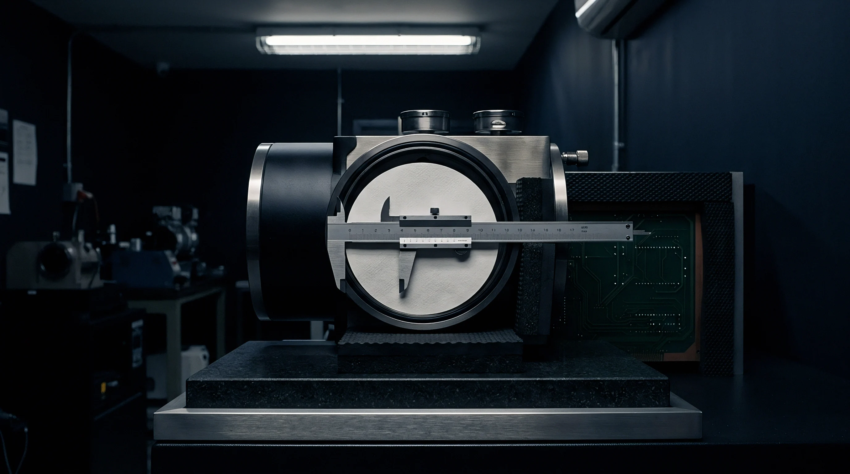
Tactile probing routines verify hole patterns, flange positions, and drawn profiles against fixed datum references. Establishing a repeatable datum reference frame requires strict alignment with 3-2-1 rules or drawing-specified Reference Point Systems (RPS). Surface contact pads set the primary datum plane, secondary locating pins control translation, and tertiary slots restrain rotation.
When loading parts, operators must follow a fixed clamping sequence to avoid inducing artificial stresses that mask natural springback.
Mechanical fixture clamps hold flexible trim lines in a constrained state.
Production checking fixtures use rigid steel or aluminum holding frames equipped with toggle clamps, boundary pin gates, and flush-and-gap blocks. Ground datum pins engage locating holes pierced during stamping, while contour blocks match the nominal part profile within specified tolerances. Sliding blocks with dial indicators or drop gages measure local flange positions relative to fixture reference faces.
Approving a fixture for first-article buyoff requires a complete Gage R&R study, requiring ANOVA GR&R values under ten percent before sign-off.
Executing an uncompromising first article metrology routine demands systematic execution across each phase of component evaluation.
- Thermal Stabilization Soak Soak the stamped part and checking fixture in a climate-controlled metrology lab at 20 degrees Celsius for at least four hours to eliminate thermal expansion errors.
- Datum Point Alignment Set the part coordinate system by probing designated RPS datum points on a CMM in the exact sequence specified on the drawing.
- Free-State Topography Scan Capture full surface geometry with a 3D optical blue-light scanner while unconstrained to measure raw springback deviation.
- Constrained Fixture Lock Clamp the stamping into the approved checking fixture using torque-limiting tools set to drawing specifications.
- Feature Position Audit Probe critical mounting holes, busbar slots, gasket groove paths, and structural points to verify GD&T true position compliance.
- Micro-Section Burr Inspection Cut, mount, and inspect cross-sections of sheared edges under a microscope to measure burr height, rollover depth, and micro-cracking.
Measuring stamped aluminum enclosure covers in a heavily clamped state masks springback that will twist the pack shell during final bolting.
During an initial tooling validation audit, a complex stamped aluminum tray bottom passed all constrained fixture checks but failed automated robot module placement downstream. Optical scanning in the unrestrained free state revealed a 3.2 mm bow across the central span, caused by residual draw stress from the die. The checking fixture had pulled the thin tray flat under heavy toggle clamps, hiding a flaw that distorted module mounting pads as soon as clamps were released.
Modifying the die’s bottoming pad radius eliminated the localized stress and fixed the assembly issue.
An uncalibrated checking fixture with misaligned locating pins resulted in forty thousand dollars in unrecoverable scrap charges during initial pilot validation.

Defect
Shearing and forming defects generated in stamping dies cause severe assembly failures downstream. Stamped aluminum trays, cooling plates, structural rails, and busbars have narrow tolerance windows where minor imperfections degrade mechanical strength, seal integrity, or high-voltage clearance. First Article Inspection identifies these flaws during tool tryout before defective die geometry is approved for production.
The primary failure modes originating in stamping dies are sheared edge defects, floor oil-canning, flange springback, and lubricant residue. Shearing conditions govern cut perimeter quality, determining burr heights and micro-fractures that reduce dielectric breakdown margins. Planar distortion across wide tray floors produces oil-canning that stresses adhesive joints during thermal cycling.
Flange springback prevents uniform gasket compression along sealing channels, compromising IP67 enclosures. Pinpointing root causes requires both dimensional metrology and metallurgical evaluation of stamped parts.

Sheared Edge Geometry and Burr Formation Limits
Mechanical blanking leaves four distinct zones along a cut edge: a rollover zone at the punch entry, a burnish land produced by plastic shear, a rough fracture zone from tensile failure, and a burr at punch exit. Punch clearance, edge sharpness, and material ductility dictate the proportion of each zone. Excessive clearance widens the fracture angle and raises burr height.
Worn cutting steels roll the sheet edge rather than shearing it cleanly, producing tall, jagged burrs.
Protruding metal burrs can penetrate thin insulating films.
Proper cutting clearance governs sheared edge quality.
| Defect Classification | Root Mechanical Mechanism | Critical Inspection Parameter | Maximum Allowable Threshold | Downstream Assembly Impact |
|---|---|---|---|---|
| Shear Edge Burr Protrusion | Dull punch radii or excessive punch clearance | Optical burr height measurement | 0.03 mm max (or < 10% stock t) | Dielectric breakdown, PET jacket puncture |
| Bistable Oil-Canning Floor | Unbalanced compressive residual stretch stress | Laser deflection amplitude scan | 1.5 mm max non-cumulative deflection | Cooling plate gap pad voiding, acoustic noise |
| Flange Springback Angular Drift | Elastic unloading following bend press stroke | CMM angular profile measurement | +/- 0.5 degrees from nominal CAD | Gasket bypass, IP67 seal pressure failure |
| Radius Micro-Cracking | Extreme tensile strain on tight bend radius | Dye penetrant / optical metallography | Zero visible micro-fractures at 50x | Structural failure under pack drop test |
| Stamping Lubricant Residue | Excess MQL application or unevaporated oil | Surface energy dynes test / FTIR | > 42 dynes/cm surface wetting | Structural adhesive delamination, laser wire porosity |

Where Does Burr Height Become an Insulation Hazard?
High-voltage busbars operating above four hundred volts demand clean cut perimeters. Heavy-gauge C11000 ETP copper is soft and ductile, making it susceptible to heavy rollover and burrs as progressive piercing punches wear. Burrs exceeding 0.05 mm intensify local electrical fields, accelerating dielectric tracking across air gaps or solid insulation.
Under creepage and clearance standards, tall burrs reduce effective spacing, raising the risk of dielectric breakdown or partial discharge arcing.
Busbars wrapped in thin polyimide or PET film are vulnerable to burr punctures. Under pack vibration and thermal expansion, sharp burr edges press into dielectric sleeves. Cyclic motion produces fretting wear, eventually forcing metal burrs through the insulation layer to ground against the pack enclosure.
First-article standards require optical micro-sectioning of sheared copper edges, enforcing a 0.03 mm maximum burr limit on electrical conductor profiles.
Residual stamping oil inhibits structural adhesive bonding.
Oil-Canning and Planar Surface Distortion in Tray Floors
Elastic instability in thin sheet metal produces out-of-plane oil-canning across broad, unsupported spans. Wide panels on bottom shields, cooling tray bases, and top covers buckle when internal forming stresses exceed critical limits. Draw beads, stretching loads, and localized coining create uneven stress fields throughout the sheet.
Under light pressure, the buckled panel snaps between two equilibrium states with noticeable displacement.
Oil-canning disrupts thermal interface material (TIM) contact under battery modules. Cooling tray floors must maintain strict planarity ~ frequently within 1.0 mm across a one-meter span. Floor deflection creates air gaps between cooling plates and module bottom plates, impeding heat transfer.
First-article inspection procedures use laser displacement grids or 3D optical scanning to map out-of-plane deflection across unsupported surfaces in the free state.
Forming micro-cracks shorten structural fatigue life.
Executing an exhaustive defect audit requires performing sequential inspection tasks to isolate physical flaws across stamped parts.
- Cut samples from structural radii and sheared busbar edges with precision wet diamond saws to avoid thermal damage to the microstructure.
- Mount specimens in epoxy, polish down to a 0.05-micron diamond slurry finish, and etch aluminum or copper alloys with matching chemical reagents.
- Inspect polished cross-sections under metallographic microscopes at 50x to 500x magnification to measure burr height, burnish land ratio, and rollover radius.
- Run dye penetrant tests along sharp 90-degree bends to find micro-cracks hidden beneath oxide or lubricant films.
- Check surface tension on adhesive bonding flanges using calibrated dyne test pens to make sure stamping oils have fully evaporated.
Progressive stamping dies for high-current copper busbars generate internal shear stress that alters electrical contact resistance after nickel plating.
When part drawings omit an explicit free-state flat pattern callout, residual flange warping is frequently defended by tooling vendors as falling within standard commercial sheet metal tolerances.


Release
Tooling release transfers operational responsibility from the die builder to manufacturing engineering. This milestone verifies that a custom stamping die produces parts that consistently satisfy dimensional, structural, and surface specifications at full production speeds. First Article Inspection Reports (FAIR) structured to standards such as AS9102 form the foundation of the sign-off package.
Entering volume production without an approved FAIR package risks elevated scrap rates and costly tool modifications.
Tooling buyoff links dimensional approval directly to contract milestone payments. Purchase agreements typically withhold a final thirty to fifty percent payment until formal First Article Inspection approval. Validating a die requires measuring parts pulled from continuous pilot runs under actual production speeds.
Isolating die machining errors from raw coil variations ensures that the supplier provides a stable, production-ready tool.

Statistical Capability Criteria for Tooling Sign-Off
Process capability indices demonstrate whether a stamping die repeatedly holds part dimensions within drawing limits. Capability studies measure critical features across a continuous run of 30 to 300 sequential press strokes without altering tool setup or press parameters. Analysis provides both short-term capability (Cpk) and long-term performance (Ppk) for key GD&T callouts.
Features governing structural assembly or IP67 sealing require a minimum Cpk of 1.67, while standard structural dimensions require at least 1.33.
Normality tests such as Anderson-Darling or Shapiro-Wilk must confirm data distribution before capability calculations are finalized. Sheet metal springback often produces skewed, non-normal distributions across multiple die cavities or varying coil batches. When non-normal behavior appears, quality engineers apply Box-Cox transformations or non-parametric percentile methods to assess capability.
A high Cpk paired with an inadequate Ppk indicates that incoming material variations ~ such as yield strength or gauge thickness ~ are driving process instability that the die cannot absorb.
High contact pressures cause structural distortion in thin-wall channels.

Production Part Approval Package Structure for Stamped Parts
Final tool acceptance packages compile dimensional reports, raw material certs, and capability studies. The Production Part Approval Process (PPAP) package for custom stamping dies provides verifiable proof of tooling capability. AS9102 Form 1 tracks part numbers and sub-assembly details; Form 2 compiles raw material mill test reports, coating certifications, and heat-treat logs for both tools and stampings; Form 3 records every ballooned drawing dimension alongside measured values, gage types, and pass/fail results for each sample part.
Material test reports (MTR) included in the FAI package confirm chemical composition, yield strength, ultimate tensile strength, and elongation for the stamped coil. Verifying that test parts were run using coil stock near nominal specification midpoints prevents the approval of dies that only function on favorable material lots. Complete buyoff packages also include maintenance documentation: exploded assembly views, standard component bills of materials, CAD files of hand-ground die surfaces, and spare tooling wear lists.
First-article sign-off establishes the final production tooling baseline.

Contractual Allocation of Die Modification and Refinement Costs
Financial disputes regarding tooling rework typically stem from ambiguous free-state drawing requirements. When FAI uncovers unacceptable springback or flange distortion, responsibility depends on whether the original drawing specified datum targets, clamping loads, and free-state limits. If out-of-spec dimensions result from die machining errors, incorrect clearance calculations, or unapproved tool changes, the builder covers all EDM rework, re-grinding, and re-inspection costs.
Engineering Change Orders (ECO) issued by the buyer after die construction begin formal Non-Recurring Engineering (NRE) negotiations. Moving hole locations, adding stiffening beads, or revising bend radii requires recutting hardened inserts or replacing entire die stations. Tooling agreements require predefined unit rates for toolmaker labor, CMM inspection, and press tryout hours to keep engineering change costs manageable.
Adherence to ISO 2768-m structural tolerances without explicit free-state notes allows suppliers to pass non-conforming, springback-warped pack tray covers.
Take a 12-station progressive die built for high-current copper busbars. The buyer specified a maximum edge burr height of 0.025 mm across all sheared surfaces, but forgot to state temperature control parameters for the tryout facility. During a pilot run on a cold winter morning, thermal contraction of the press ram tightened punch clearance, producing burr-free samples that easily passed First Article Inspection.
When mass production started in summer at ambient temperatures ten degrees higher, thermal expansion shifted ram alignment, widening punch clearance and throwing burrs past 0.060 mm across twenty thousand parts. Because the contract never specified thermal stabilization during FAI, the buyer ended up in contested negotiations over tool re-alignment costs.
Mandating a 300-piece continuous run at full production speed in the contract puts the financial responsibility for secondary die tuning back on the vendor.