Mechanical Interface Design and Compliance Ownership in Custom Pack Sourcing
Custom pack sourcing demands explicit engineering stack-up allowances for cell swell alongside contractual assignment of compliance dossier ownership.


Swell
Lithium-ion pouch and prismatic cells undergo reversible dimensional changes during cycling, along with permanent volumetric growth over their working life. Inserting lithium into the graphite anode expands the lattice, causing transient thickness increases of 1.5% to 4.0% between zero and one hundred percent state of charge. Solid electrolyte interphase growth and lattice degradation add another 6% to 15% in unrecoverable expansion over eight hundred to two thousand full equivalent cycles, depending on the anode’s silicon blend ratio.
Enclosures designed without room for these mechanical shifts risk localized over-compression, crushed separators, internal shorts, or structural casing failure.
Mechanical interface specifications require setting a clear initial clamping pressure while accommodating long-term swelling. For pouch architectures, optimal stack pressure ranges between 20 kPa and 70 kPa. Operating below 15 kPa allows active layers to delaminate during cycling, which accelerates capacity loss and gas generation.
Exceeding 120 kPa crushes the porous structure of polyethylene or polypropylene separators, creating conditions for localized dendrite growth. Engineering teams typically manage this operating window by placing open-cell microcellular polyurethane or silicone foam pads between cell sheets.

Volumetric Expansion and Stack Compression
Selecting the right foam thickness means evaluating the cushion material’s stress-strain curve across the entire operating temperature envelope. These foams show non-linear spring behavior, stiffening when cold and losing rebound resilience after extended compression at elevated temperatures.
Calculating the necessary initial gap relies on the cell’s maximum expected thickness at end-of-life under full state of charge. A cell with a nominal 10.00 mm thickness and a plus-or-minus 0.30 mm manufacturing tolerance expands by 12% at end-of-life, bringing maximum cell thickness to 11.53 mm. Across a ten-cell stack, net expansion can accumulate to 15.3 mm over its service life.
If rigid end-plates lock down the stack without compliant foam pads, forces generated by the expanding layers quickly exceed 5 kN, destroying the module frame or buckling the cell tabs.
Open-cell polyurethane cushions maintain effective stack pressure only when compressed within twenty to fifty percent of their unconstrained thickness.

Tolerance Stack-Up Calculation
Tolerance stack-up calculations need to balance three separate sources of variance: cell manufacturing limits, foam sheet thickness tolerances, and module frame machining tolerances. Summing worst-case extremes yields heavy, over-engineered enclosures that compromise energy density, so development teams typically use Root Sum Square statistical methods to establish nominal dimensions.
Because thickness increases continuously over time, designers set initial stack gaps to compress the foam pad by thirty percent when installing new cells at fifty percent state of charge. As permanent growth accumulates over time, foam compression approaches forty-five percent near end-of-life, keeping stack pressure within safe limits. Mechanical drawings define the explicit bolt-torque sequence for end-plates to ensure initial clamping stress is evenly distributed across the pouch faces.
Evenly distributed mechanical pressure across every cell face helps maintain capacity retention over cycle life while keeping the outer housing from distorting.


Chassis
Pack enclosures carry structural loads, shield internal hardware from impacts, and keep out moisture and dust. Die-cast aluminum alloys deliver structural rigidity at low weight, while extruded profiles make it easy to scale enclosure length without heavy NRE investments. Sheet metal designs keep upfront tooling costs down, though riveted or welded seams introduce potential leak paths that require strict process control in manufacturing.
Meeting IP67 or IP68 ingress protection requires continuous perimeter gaskets that can handle thermal cycling and physical shock. Elastomeric seals made of ethylene propylene diene monomer or fluoroelastomers need tight compression control, usually capped between twenty-five and thirty-five percent of their relaxed cross-section. Cast housings often include molded compression stops so assembly technicians cannot over-torque fasteners, preserving gasket resilience across a ten-year service life.
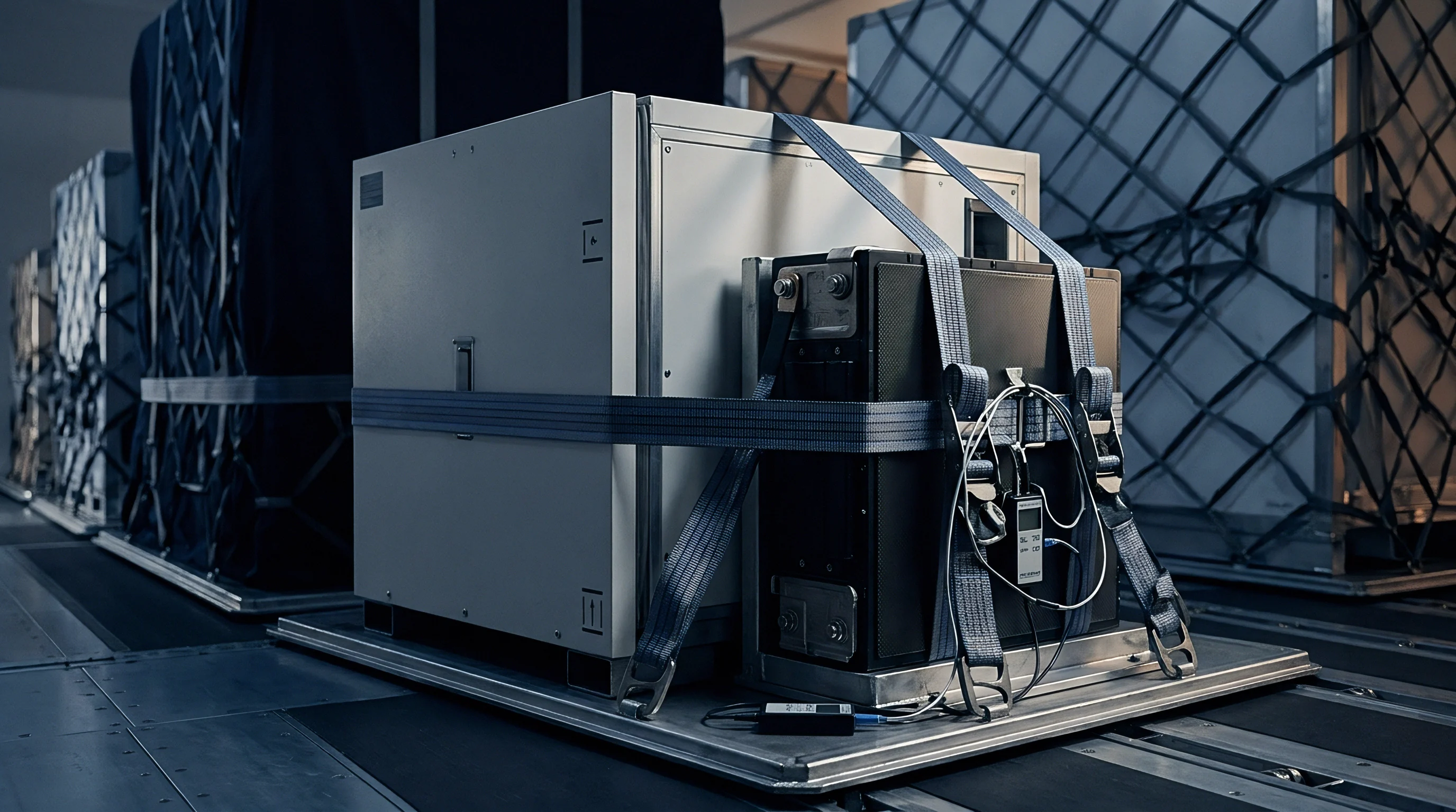
Enclosure Structural Topology and Ingress Sealing
Dynamic stress testing shows that pack structures must absorb vehicle or industrial vibration without passing strain along to cell tabs or high-voltage interconnects. Resonant frequencies below 30 Hz align with typical axle inputs, which can quickly fatigue rigid copper busbars. Adding structural ribbing and strategic mounting points moves natural resonance above 120 Hz, isolating delicate internal joints from road shock.
Water vapor entering through microscopic housing seams turns into localized condensation during sudden temperature drops, which degrades internal insulation resistance and triggers earth-fault errors in the Battery Management System.
Thermal Interface Management under Dynamic Loads
Conducting heat from cells to the chassis depends on thermal interface materials applied between the cell surfaces and the aluminum sink. Liquid gap fillers and phase-change pads bridge microscopic surface gaps, pulling thermal resistance below 0.5 K-cm²/W. Dispensing liquid fillers introduces process variation, however; uneven bead volumes can create high spots that tilt cell modules and misalign terminal tabs relative to busbar attachment points.
| Enclosure Architecture | Tooling Cost Band (USD) | Ingress Seal Reliability | Structural Stiffness-to-Weight | Thermal Conduction Path |
|---|---|---|---|---|
| Die-Cast ADC12 Aluminum | 80,000 to 180,000 | High (Machined Gasket Grooves) | High | Direct Integrated Sink (120 W/mK) |
| Extruded 6063-T6 Profile | 15,000 to 45,000 | Moderate (End-Cap Perimeter Joints) | Very High | Conduction Plate Required (180 W/mK) |
| Stamped 304 Stainless Sheet | 35,000 to 90,000 | Low to Moderate (Continuous Welds Needed) | Moderate | Poor Conduction (16 W/mK) |
| Injection Molded Polycarbonate/ABS | 50,000 to 120,000 | High (Molded O-Ring Channels) | Low | Insulative (0.2 W/mK, External Sink Needed) |
Unchecked thermal gradients within a pack accelerate degradation in the hotter cells, creating string imbalance and triggering early capacity cutoffs.
- Gasket over-compression failure occurs when assembly fasteners are torqued past limits without mechanical stops, permanently crushing the elastomer and destroying its elastic recovery.
- Busbar weld fatigue fracture results from chassis twisting under load, which transfers mechanical strain directly through rigid copper joints.
- Galvanic corrosion of joints develops when raw aluminum housings contact stainless steel fasteners in humid, salty environments without isolating coatings.
- Liquid cold-plate deformation occurs when coolant pressure surges past limits during fast charging, bowing the plate upward into the cell stack cavity.
A chassis enclosure designed without mechanical stops over-compresses elastomeric gaskets, destroying seal resilience within six months of field deployment.
Designing an enclosure without compression stops along the perimeter gasket invites seal failure under thermal cycling, compromising internal electronics and risking field warranty claims.


Harness
Internal electrical connections must handle high continuous current loads while delivering clean signals to cell-monitoring electronics. Busbars made from C11000 ETP copper provide 100% IACS conductivity, though nickel-plated aluminum busbars cut conductor weight by almost half. Joining aluminum busbars to copper cell tabs requires ultrasonic wedge welding or bi-metallic transition cladding to prevent brittle intermetallic compounds from building up and increasing joint resistance over time.
Flexible busbars formed from laminated thin copper foil help isolate cell-to-cell movement caused by thermal expansion or chassis flex. Rigid busbars transfer these expansion forces directly into the cell terminals, where they can breach header seals. Replacing discrete wire harnesses with polyimide flex circuits for BMS voltage and temperature sensing simplifies pack assembly and eliminates common wiring errors.
High-Current Busbars and Sensing Assemblies
Vibration testing regularly exposes stress points where rigid voltage-sensing leads join heavy power terminals. Adding stress-relief loops to signal harnesses prevents conductor fatigue as the pack expands longitudinally.
Signal routing needs to stay clear of high-current switching paths to shield BMS analog front-end electronics from electromagnetic interference. Inductive coupling from sudden current pulses can distort cell voltage readings and trip false over-voltage faults during rapid load transients.

Creepage, Clearance, and Isolation Geometry
High-voltage packs operating between 400 V and 800 V must strictly follow the creepage and clearance dimensions specified in IEC 60664-1. Creepage is the shortest path along an insulating surface between conductors, whereas clearance is the direct distance through air. Tight pack layouts often narrow these air gaps, making physical insulating barriers or conformal coatings necessary to prevent dielectric breakdown in humid environments.
IEC 60664-1 specifies a minimum clearance distance of 3.2 mm for 800-volt battery systems operated under Pollution Degree 2 conditions.
Creepage paths across raw fiberglass structures degrade over time if conductive dust or moisture collects inside the enclosure.
When continuous vibration frays voltage sense harnesses against aluminum module frames, the issue often stems from external chassis flex exceeding the shock response spectra defined in the original specification.


Certification
Compliance management carries significant commercial risk in custom pack projects. A finished battery pack is a distinct regulated entity that requires its own safety documentation, regardless of cell-level certifications. Securing UN 38.3 transport clearance involves eight specific tests, including altitude simulation, thermal cycling, vibration, shock, short circuit, impact, overcharge, and forced discharge.
Cell suppliers maintain UN 38.3 approvals for bare cells, but adding a custom enclosure or BMS voids those approvals at the pack level.
Full pack assemblies must undergo UN 38.3 qualification using final production housings and production-intent BMS firmware to gain dangerous goods shipping clearance. Moving uncertified packs requires costly Class 9 prototype exemptions that limit transport options and add significant logistics overhead.

Regulatory Dossier Allocation and Testing Frameworks
Safety standards vary by application: IEC 62133-2 applies to portable lithium systems, UL 1973 governs stationary energy storage, and UL 2580 covers electric vehicle traction packs. Contracts must clearly identify whether the buyer or the pack integrator serves as the primary applicant on these regulatory dossiers. The listed applicant holds the certificate, manages engineering change notices, and assumes legal responsibility if field issues expose regulatory compliance gaps.
| Standard | Scope of Evaluation | Primary Test Targets | Typical Lead Time | Default Ownership Assignment |
|---|---|---|---|---|
| UN 38.3 | Transport Safety Clearance | Altitude, Vibration, Thermal, Shock, Short Circuit | 4 to 6 Weeks | Pack Integrator / Custom Manufacturer |
| IEC 62133-2 | Industrial/Portable Battery Safety | Thermal Abuse, Forced Internal Short, Overcharge | 6 to 8 Weeks | OEM / Product Sourcing Entity |
| UL 1973 | Stationary Battery Safety | Dielectric Withstand, Drop, Thermal Runaway Propagation | 12 to 16 Weeks | OEM / Product Sourcing Entity |
| EU 2023/1542 | Battery Passport & Sustainability | Carbon Footprint, Recycled Content, Supply Chain Due Diligence | Ongoing Administrative | Importer of Record / Brand Owner |

How Does Regulatory Transfer Shift Legal Exposure during Mid-Cycle Cell Revisions?
Substituting a cell model within a certified pack design immediately triggers regulatory review. Certification bodies assess whether the swap is a minor design update or requires repeating full test suites under UN 38.3 and IEC 62133-2. When a replacement cell offers higher energy density or different internal resistance, laboratories generally mandate repeating the complete thermal runaway and overcharge test blocks.
Who holds the regulatory master file dictates who pays for re-qualification when supply chain issues force a cell substitution. Procurement contracts that do not explicitly assign these re-testing expenses leave buyers exposed to unexpected delays and unbudgeted lab fees.
- UN 38.3 test dossier confirming that the exact production build, BMS firmware release, and cell model passed transport safety testing without fire or rupture.
- Material safety data sheets detailing chemical hazards, suitable fire suppression media, and emergency response procedures for the complete battery pack.
- Declaration of conformity signed by the manufacturer verifying compliance with relevant regional rules, such as CE, UKCA, or FCC directives.
- Cell grading certificates documenting baseline capacity distribution, internal resistance metrics, and batch traceability codes for all cells in the build.
Compliance certificates expire instantly when an unapproved cell substitution occurs inside a certified battery pack enclosure.
Under Clause 5.2 of standard procurement contracts, the party listed as the regulatory applicant of record assumes financial liability for recall costs caused by non-compliant certification filings.


Amortization
Custom pack sourcing comes down to balancing upfront Non-Recurring Engineering expenses against long-term unit costs. Injection molds for cell holders and end-caps demand significant early investment, running from $30,000 for basic plastic brackets to over $150,000 for multi-cavity liquid-cooled enclosure tooling. Contracts must explicitly assign tooling ownership; otherwise, the supplier keeps physical possession of the dies and can use that leverage during annual price reviews.
Aluminum injection tooling usually lasts 20,000 to 50,000 shots before key dimensions drift, while hardened steel molds hold tolerances for up to 500,000 shots. Sourcing teams spread these tooling expenses over expected production volumes to evaluate total landed unit costs across competing suppliers.

Tooling Non-Recurring Engineering and Fixture Lifecycle
Ultrasonic weld tips, laser alignment tooling, and assembly nests all suffer mechanical wear that leads to dimensional drift over long production runs. First Article Inspection confirms that initial off-tool parts match drawing tolerances before approving full-scale manufacturing.
Evaluating a prototype build against high-volume production highlights the impact of amortized tooling. In this scenario, a program requires 10,000 units annually over three years, reaching 30,000 total units.
Worked Cost Sensitivity on Custom Pack Tooling Recovery
Option A uses soft tooling priced at $20,000 but carries a piece-part assembly cost of $180.00 per unit because of manual welding and handling. Option B commits $120,000 to hard production tooling and automated welding nests, driving the per-unit assembly cost down to $171.00.
| Production Volume (Units) | Option A Amortized NRE ($20k Tooling) | Option A Total Unit Cost ($) | Option B Amortized NRE ($120k Tooling) | Option B Total Unit Cost ($) |
|---|---|---|---|---|
| 1,000 | $20.00 | 200.00 | $120.00 | 291.00 |
| 5,000 | $4.00 | 184.00 | $24.00 | 195.00 |
| 11,111 (Break-Even) | $1.80 | 181.80 | $10.80 | 181.80 |
| 30,000 (Program Target) | $0.67 | 180.67 | $4.00 | 175.00 |
Option B reaches cost parity at 11,111 units. Past that threshold, hard tooling delivers net savings, reducing final unit costs by $5.67 at the 30,000-unit program target while providing better dimensional consistency across the assembly line.
- Verify raw material mill certificates for housing alloys and resin batches to confirm chemical composition meets engineering standards.
- Perform full three-dimensional coordinate measuring machine scans on initial molded housings to verify key drawing dimensions and tolerances.
- Run high-voltage dielectric insulation tests on prototype enclosure barriers before installing active cell modules.
- Perform initial tear-down shear tests on ultrasonic busbar welds to establish baseline strength metrics and process capability indices.
- Issue a formal First Article Inspection sign-off to freeze drawing revisions before releasing high-volume purchase orders.
Contracts should include specific indemnity clauses that protect the buyer if a supplier-owned injection mold wears past allowable tolerances before fulfilling the agreed program volume.

Indemnity
Responsibilities shared between cell manufacturers, pack integrators, and OEM brand owners create complex legal and technical boundaries. When a custom battery fails in service, determining root cause means isolating whether the issue stems from a cell manufacturing defect, a pack assembly error, or flawed BMS firmware execution.
BMS firmware controlling current thresholds, balancing routines, and thermal limits directly affects cell life. If a buyer defines custom firmware settings that operate outside the cell manufacturer’s recommended window, the cell vendor usually voids capacity and cycle-life warranties. Because the pack integrator only covers physical assembly defects, the buyer remains liable for field failures caused by custom software logic.

BMS Firmware Boundaries and Field Failures
To resolve warranty disputes, modern procurement contracts mandate onboard event logging in the BMS memory. The system records peak temperatures, over-current events, short-circuit trips, and cumulative state-of-charge history in non-volatile storage.
Raw telemetry logs give failure analysis teams clear data during investigations. If a pack experiences thermal distress, stored records help determine whether the incident resulted from external shorting or an internal cell flaw.

Split Warranty Allocation Protocols
Supply agreements typically split cell warranties from pack assembly guarantees. Cell manufacturers warrant that bare cells satisfy capacity, resistance, and cycle-life specs within specified operating limits. The pack integrator guarantees structural integrity, weld quality, weather seals, and wire harness assembly.
Well-drafted contracts establish a joint failure analysis process for warranty returns. These agreements set target reject thresholds ~ often 0.5% of delivered volume ~ above which the pack supplier covers containment actions, field labor, and lab diagnostics. Clear mechanical drawings, defined tolerance limits, and explicit compliance assignments allow companies to source custom packs without taking on unquantified financial risk.