Gas Phase Hydrodynamics and Thermal Condensate Entrainment Limits in Large Format Tool Steel Printing
Laminar gas velocities between 1.8 and 2.5 meters per second prevent submicron condensate soot from redepositing into large-format tool steel melt tracks.


Duct
Inert gas enters the build volume through an inlet plenum designed to sweep evaporation products clear of the melt pool before they attenuate the laser beam. In large-format powder bed machines processing tool steels such as DIN 1.2344 (AISI H13) or DIN 1.2709 (maraging 300), the gas velocity across an 800 mm build plate dictates whether vaporized alloying elements exit the optical path or linger as a submicron suspension above the bed. Below a local crossflow velocity of 1.8 meters per second, the thermal plume lifts into the upper chamber atmosphere, cooling and agglomerating until oxidized, spherical condensate balls between 0.2 and 4.5 micrometers in diameter drop back onto the powder layer.
When several high-energy laser beams fire simultaneously across a large surface area, localized thermal uplift interferes with the horizontal gas stream. Each 1 kW fiber laser creates a recoil pressure cavity, throwing off liquid spatter droplets alongside a continuous jet of metallic vapor rich in iron, manganese, and chromium. The cross-sectional area of the supply duct sets the static pressure distribution across the processing zone; variations greater than 12 pascals over a 600 mm span trigger recirculating vortices near the chamber walls that trap metallic vapors directly above active scan vectors.
A crossflow velocity variation exceeding 0.35 meters per second across the build plane correlates directly with uneven tensile elongation in multi-laser overlap regions.
Uneven gas distribution also alters how effectively the main stream entrains debris. Argon has a dynamic viscosity of 2.23 × 10⁻⁵ Pascal-seconds at room temperature, rising past 5.5 × 10⁻⁵ Pascal-seconds inside the hot envelope directly over the melt tracks. Stream velocity must overcome the buoyant lift rising from a melt pool surface above 2,800 Kelvin.
If the convective momentum of the laminar shroud falls below that buoyancy threshold, the evaporation column punches straight through the horizontal flow. Tool steel builds suffer heavily when this happens, as rapid volatilization of high-vapor-pressure elements degrades the local shielding chemistry.
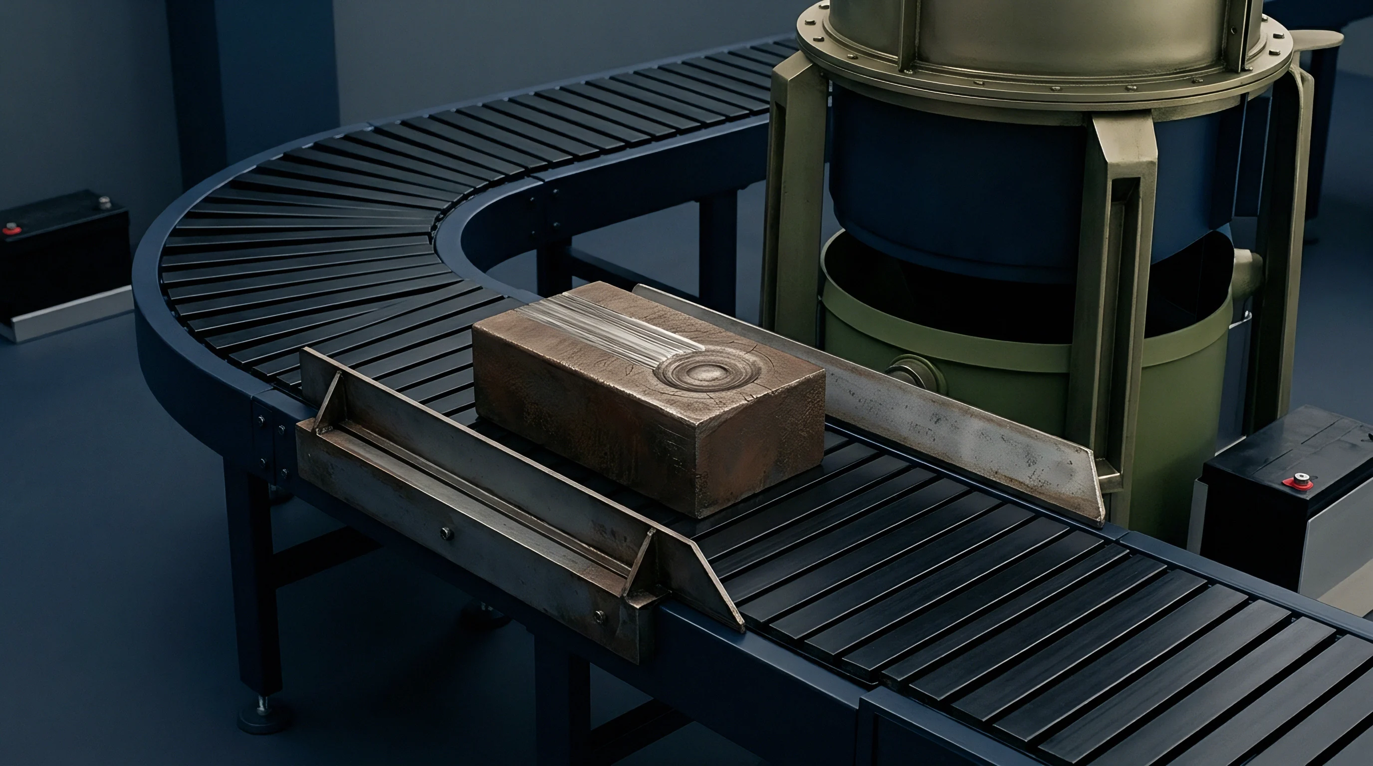
Gas Velocity Gradients and Volatilization Chemistry
Manganese reaches an equilibrium vapor pressure of 100 pascals at 1,500 Kelvin, whereas iron requires 1,900 Kelvin to reach that same evaporation rate. Melting AISI H13 tool steel ~ containing roughly 0.40 percent carbon, 5.00 percent chromium, 1.30 percent molybdenum, and 1.00 percent vanadium ~ selectively strips manganese and chromium from the pool. These vaporized elements condense into an ultra-fine aerosol of mixed oxides and metallic clusters that link into high-surface-area chains as they drift toward the exhaust.
If the gas stream slows between the inlet diffuser and the center of the build plate, these particulate chains settle early. How far an entrained condensate travels before gravity pulls it down onto fresh powder depends entirely on the local velocity profile. On long vector passes, stagnant boundary layers trap airborne condensate that blocks incoming laser energy.
Scattering through this aerosol cloud can cut nominal beam irradiance by up to 14 percent at the focal spot.
That drop in delivered energy density leaves incomplete fusion between adjacent hatch passes. In tool steel dies, subsurface lack-of-fusion voids create stress concentrations under cyclic thermal shock, serving as primary nucleation sites for fatigue cracking in die-cast inserts and deep-draw battery tooling. Failing to sweep vaporized metal away before it cools below liquidus temperatures drives up scrap rates on large tool blocks.


Drag
Particle movement through the argon shield follows hydrodynamic regimes defined by the particle Reynolds number. Condensates forming in the laser plume measure between 20 nanometers and 2 microns across, placing their motion in the Stokes-Cunningham slip correction regime. Gas drag on these submicron clusters balances against gravity, electrostatic forces from the plasma, and thermophoretic repulsion off the incandescent track.
Because tool steel generates heavy metallic vapor, effective entrainment depends on maintaining a Reynolds boundary condition that prevents flow detachment across the recoater assembly.
Upstream flow conditioners determine whether the gas sweep stays laminar or turns turbulent over the build area. Tall tool steel geometries disrupt the flow path, creating low-velocity separation wakes behind solid metal features. These wakes slow local convective transport, drawing particulate from nearby melt pools into swirling eddies behind the trailing face of the part.
| Gas Medium | Mean Velocity (m/s) | Dynamic Viscosity (Pa·s) | Reynolds Number (L=0.8m) | Flow Regime |
|---|---|---|---|---|
| Argon (ambient, 298 K) | 1.5 ± 0.1 | 2.23 × 10⁻⁵ | 95,400 | Transitional Boundary |
| Argon (heated layer, 473 K) | 2.2 ± 0.15 | 3.21 × 10⁻⁵ | 98,200 | Transitional Boundary |
| Nitrogen (ambient, 298 K) | 1.8 ± 0.1 | 1.78 × 10⁻⁵ | 96,900 | Transitional Boundary |
| Helium-Argon 30/70 Mix | 3.0 ± 0.2 | 2.35 × 10⁻⁵ | 76,500 | Laminar Dominant |
Higher gas density improves momentum transfer to suspended particles. Nitrogen has a lower molecular mass than argon, reducing drag on larger condensate agglomerates at a given velocity, but argon remains the standard carrier for high-carbon tool steels to prevent chromium nitride formation during thermal cycling. Adding helium reduces overall gas density while increasing thermal conductivity, which cools the boundary layer; however, the lower molecular mass cuts drag coupling, requiring higher volumetric flow rates to move the same mass of heavy iron-chromium condensate.

Thermophoresis and Plume Entrainment Mechanics
Thermal gradients between the melt line and incoming cool gas generate steep thermophoretic forces. Temperature drops by roughly 2,000 Kelvin within two millimeters of the liquid puddle surface. This gradient repels submicron condensates from the hottest region, driving them up into the main crossflow.
If the gas stream lacks sufficient dynamic head, thermophoresis pushes condensates into the low-velocity stagnation zone right above the beam focus.
Particle capture depends on the balance between upward thermophoretic drift and horizontal fluid drag. When convective momentum dominates, the condensate plume deflects more than 45 degrees toward the exhaust, leaving a clear line of sight for co-axial pyrometers and tracking optics. If gas drag drops below the clearing threshold, the plume remains vertical.
The laser then fires directly through the condensate, remelting it into a secondary shower of superheated droplets that rain onto adjacent consolidated tracks.
- Gas velocity calibration requires balancing static line pressure at the inlet rail to hold flow variation across the build plate width within five percent of target velocity.
- Exhaust plenum balancing maintains equal pressure drop across every extraction port, preventing flow channeling that leaves chamber corners stagnant during long runs.
- Recirculation filter monitoring tracks differential pressure across high-efficiency particulate air elements to keep total chamber volume exchange rates above thirty cycles per hour.
- Gas temperature management rejects process heat through liquid-cooled heat exchangers, keeping incoming gas density stable over continuous multi-day builds.
Tool steel parts require near-full density to survive cyclic loading in injection molding or die stamping, where porosity above 0.05 percent initiates cracking along primary carbide networks. Crossflow gas must clear condensates completely before subsequent laser passes cross the same area.
Plume deflection angles that fail to clear the main optical axis cause uncorrectable laser power degradation over long tool builds.
Stagnant gas regions lead directly to unbonded inclusions. Particles suspended in the boundary layer scatter incident laser light via Rayleigh and Mie mechanisms, widening the focal spot and reducing power density at the surface. This shifts melting from keyhole penetration to shallow conduction mode, which fails to fully melt adjacent powder boundaries.
The resulting inter-layer lack-of-fusion voids will not heal during hot isostatic pressing if trapped argon prevents the cavities from collapsing under pressure.
A stable laminar profile carries fine debris into the exhaust ports without dragging it across unexposed powder bed areas.


Soot
Micro-condensate buildup on chamber surfaces poses a constant contamination threat during extended tool steel builds. These dark, oxidized deposits resemble fine soot, forming friable crusts made of submicron spheroids. On large powder bed machines running builds over one hundred hours, kilograms of soot accumulate on optical windows, gas tiles, and powder delivery troughs.
Because tool steels like AISI D2 or M2 contain substantial carbon, molybdenum, and tungsten, this soot differs radically in composition from the starting powder stock.
Differential scanning calorimetry shows that condensate soot contains elevated concentrations of volatile metal oxides, which lower its local melting point compared to the nominal alloy matrix. If soot flakes fall from the exhaust hood onto the powder bed, subsequent laser passes cannot fully assimilate them into the melt pool. The resulting inclusion sits as an oxide cluster inside a carbon-depleted halo, promoting brittle intergranular cracking along solidified cell boundaries.

Condensate Deposition Profiles and Chemical Fractionation
Chemical analysis of tool steel condensate shows heavy segregation of volatile elements, which concentrate in the finest airborne soot particles. This composition drift between virgin powder and captured soot requires strict isolation of process waste during powder recycling.
- Manganese enrichment occurs because manganese vaporizes at lower temperatures than iron, producing soot with three to five times the manganese concentration of the starting powder.
- Silicon segregation concentrates silica on the surface of submicron particles, forming non-metallic glass skins that block metallurgical bonding during layer fusion.
- Chromium depletion in the melt pool matches chromium accumulation in the exhaust ductwork, reducing corrosion resistance in heavily scanned regions of the die.
- Carbon concentration within soot clusters alters local hardenability, creating brittle martensitic zones that crack under clamping loads without prior plastic deformation.
Gas flow must prevent soot from settling onto fresh powder. If the recoater blade passes over loose soot, it shears and smears the low-density oxide agglomerates into the powder bed, spreading contaminants into lower layer depths and creating macro-inclusions that ruin final surface finishes.
| Element | Nominal Powder (wt%) | Plume Condensate (wt%) | Spatter Particulate (wt%) | Segregation Factor |
|---|---|---|---|---|
| Iron (Fe) | 90.2 ± 0.5 | 78.4 ± 1.2 | 89.1 ± 0.6 | 0.87 (Depleted) |
| Chromium (Cr) | 5.20 ± 0.15 | 8.60 ± 0.35 | 5.45 ± 0.20 | 1.65 (Enriched) |
| Molybdenum (Mo) | 1.40 ± 0.08 | 1.10 ± 0.05 | 1.38 ± 0.07 | 0.78 (Depleted) |
| Vanadium (V) | 1.00 ± 0.05 | 0.85 ± 0.04 | 0.98 ± 0.05 | 0.85 (Depleted) |
| Manganese (Mn) | 0.40 ± 0.03 | 1.95 ± 0.12 | 0.48 ± 0.04 | 4.87 (Enriched) |
| Oxygen (O) | 0.02 ± 0.005 | 7.20 ± 0.40 | 0.12 ± 0.02 | 360.0 (Enriched) |
Oxygen levels in the soot surge as hot metallic clusters scavenge residual oxygen and moisture from circulating argon. Even when chamber sensors record under five parts per million of oxygen, the high specific surface area of the submicron particles drives chemisorption, converting metallic vapors into stable oxide nanoparticles with oxygen contents reaching several weight percent.
Secondary gas filtration is intended to remove process-generated aerosols before the recirculation loop returns gas to the build zone, though submicron particles routinely bypass standard filters.
Fine particulate bypasses standard cyclone separators and loads primary HEPA filters quickly. As filter cake builds, backpressure rises and reduces fan delivery across the closed loop. Total gas flow declines steadily over multi-day builds unless variable-frequency drives automatically ramp up fan speed in response to pressure sensors.
Operators often overlook this gradual loss of flow until porosity defects show up on finished components.
Without continuous monitoring, loop balance drifts over time, leaving unmonitored systems prone to recirculating contaminated gas during final build layers.
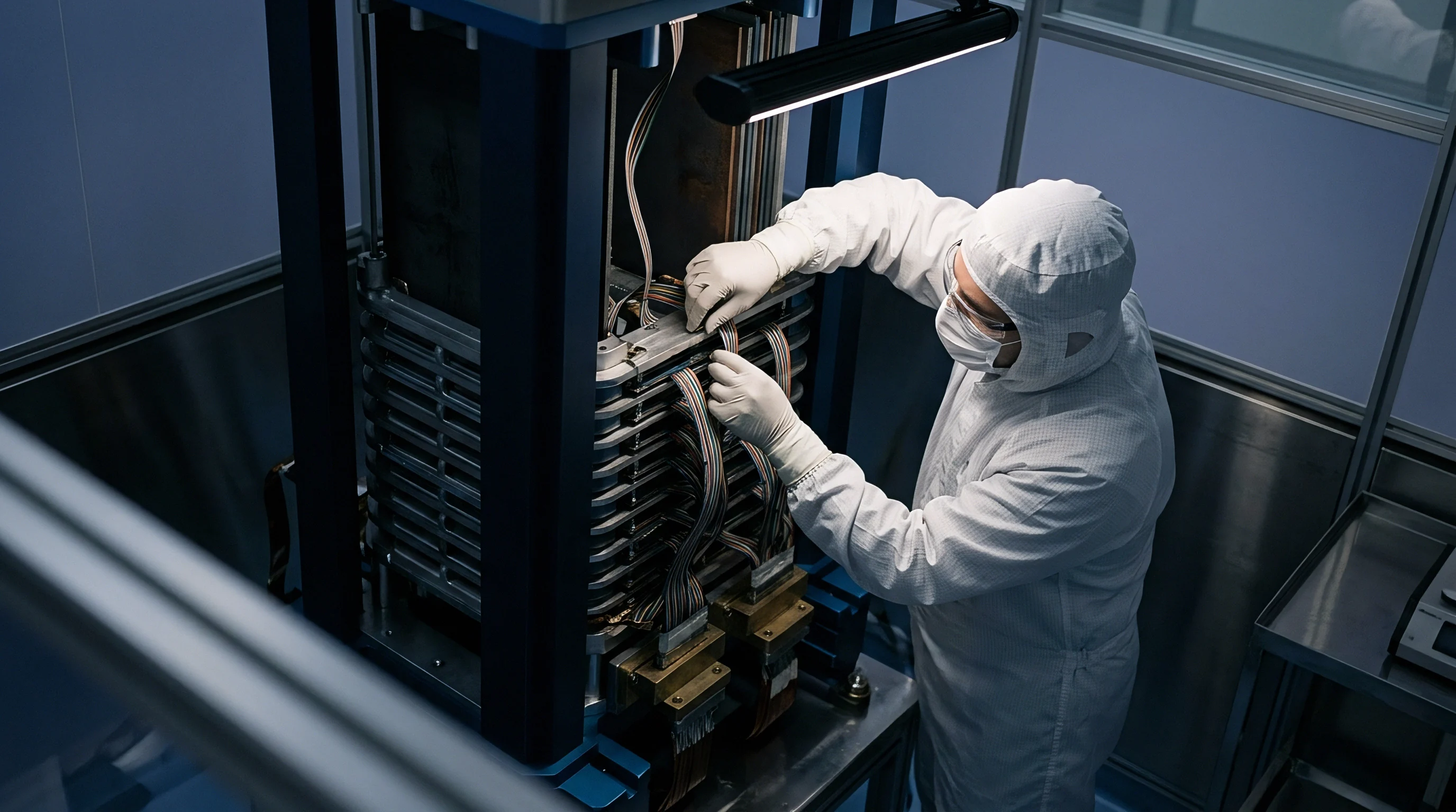

Defect
Porosity, inclusions, and lack-of-fusion voids stem directly from gas-metal interactions in the boundary layer. Under scanning electron microscopy, failure modes caused by inadequate plume extraction show distinct features. Spherical gas pores between 5 and 30 micrometers in diameter point to gas rejection during rapid solidification ~ typically caused when condensate bearing moisture or air enters the pool, releasing hydrogen or carbon monoxide that gets trapped by the advancing dendritic front.
Irregular, angular voids filled with un-melted powder mark lack-of-fusion defects. These occur when soot clouds or heavy spatter attenuate the laser before it hits unprocessed powder. Large-format tool steel systems often use multi-scanner setups where as many as twelve lasers operate at once in a single chamber; if a beam fires through the plume of an adjacent scanner, transmission drops immediately.
ASTM F3049 powder characterization standards require strict monitoring of reused tool steel feedstocks to catch progressive oxygen buildup.
Inter-layer boundaries accumulate defects whenever gas flow fails to clear the platform edges. These inclusions degrade mechanical performance under cyclic loads. In tools like printed AISI H13 or maraging steel dies used for automotive battery enclosures, surface integrity governs lifespan; microscopic inclusion clusters on a tool face pit rapidly under high-pressure aluminum stamping.

Mechanical Property Degradation across Flow Directions
Anisotropy in printed tool steel aligns closely with gas flow direction relative to laser hatch vectors. Test coupons built parallel to gas flow show higher fracture toughness and fewer inclusions than those oriented perpendicular to flow. Parts built downstream near exhaust registers experience constant exposure to soot and spatter carried across the full width of the plate.
Consider an AISI H13 tooling block measuring 400 by 400 by 300 millimeters built at 400 watts laser power, 50 micrometers layer thickness, 1,000 millimeters per second scan speed, and 100 micrometers hatch spacing. At these parameters, each laser deposits roughly 20 cubic centimeters of solid steel per hour. At a density of 7.8 grams per cubic centimeter, each optical channel solidifies 156 grams of steel hourly.
Depending on peak melt pool temperatures, vaporization consumes between 0.5 and 1.5 percent of that mass.
A single beam thus vaporizes around 1.5 grams of alloy per hour. Across a four-laser machine, six grams of metallic vapor enters the chamber every hour, producing roughly 1.2 × 10¹⁴ aerosol particles. Over a 100-hour build, the gas system must evacuate 600 grams of submicron condensate without letting a single milligram settle back onto active scan paths.
A flow interruption of just two seconds drops enough soot to seed dozens of internal voids.
High-resolution computed tomography reveals these defect bands as planar arrays matching the scan path. Ultrasonic inspection often misses submicron oxide films, which split open during subsequent heat treatment. During austenitizing and quenching, differing expansion rates between the steel matrix and brittle oxide films initiate microcracks that fail the tool during press tryout.
Premature insert failure in high-volume production presses brings severe financial fallout. Stamping lines for battery module components operate at twenty to forty strokes per minute under thousands of kilonewtons of force. If an internal lack-of-fusion void causes a die to shatter under cyclic impact, the resulting fragments can destroy the press ram, ruin automated coil feeders, and shut down assembly lines for weeks.
Does current in-situ optical monitoring react fast enough to catch sub-millisecond aerosol attenuation before energy deficits seed unrecoverable lack-of-fusion flaws inside large tool steel builds?

Settlement
Disputes between print service bureaus, powder suppliers, and production stampers usually center on defect attribution. When a finish-machined H13 die component breaks after ten thousand strokes, liability hinges on whether the root cause was mechanical design, defective powder atomization, or poor gas flow during printing. Sourcing contracts need explicit verification and acceptance criteria before parts proceed to post-processing, heat treatment, and final sign-off.
Audits rely heavily on machine telemetry logs. High-end large-format systems log static inlet pressure, mass flow rate, oxygen concentration, and filter backpressure every 100 milliseconds. If telemetry shows gas velocity dipped below specification while printing critical die teeth or cooling channels, the operator carries responsibility for resulting defects.
Without logged telemetry mapped to part coordinates, service providers often attribute internal porosity to baseline powder variation.
Contractual Architecture for Large Tool Additive Manufacturing
Procurement teams managing multi-cavity tooling programs for automotive or battery pack stampings need explicit testing protocols in initial purchase orders. Mandating destructive coupon testing and non-destructive evaluation tied to payment milestones ensures clear quality gates.
Master services agreements should include explicit warranties covering inclusion thresholds and flow integrity. Under these terms, the service bureau guarantees density above 99.8 percent on critical working surfaces, verified via Archimedes testing and sectioned metallography of witness coupons printed along the exhaust edge of the platform. Coupons placed in these downstream corners experience the worst gas stagnation and soot buildup, ensuring that if they pass fatigue testing, the centrally located die component meets higher density standards.
Contracts should specify that porosity exceeding 0.1 percent in designated wear areas constitutes a non-conformance event requiring a full credit or reprint at the supplier’s expense, including reimbursement for lost CNC machining and polishing time. Clear terms prevent disputes between the powder vendor ~ guaranteeing gas-atomized oxygen levels under 200 parts per million ~ and the print shop, whose inadequate chamber sweep allowed soot scavenging that drove finished part oxygen content past 800 parts per million.
Under ISO 17296-3 framework for additive supply contracts, explicit non-conformance terms assign liability for process-induced gas defects to the service provider once incoming powder chemistry passes initial receiving inspection.