Predictive Long Term Interfacial Creep Relaxation Mechanics across Large Format Battery Thermal Plates
Compressive creep and viscoelastic stress relaxation in thermal interface materials drop contact pressure, triggering thermal impedance spikes across battery plates.

Viscoelasticity
Large-format prismatic and pouch cells expand and contract cyclically during routine charge and discharge. That breathing motion imposes fluctuating mechanical strain on cooling plates mounted across cell bases or side walls. During initial module pre-loading, elastomeric thermal interface materials compress to bridge manufacturing clearances and establish a conductive path away from the cells.
Over months and years in the field, sustained pressure drives molecular rearrangement through the polymer matrix. As polymer chains reorient under load, the counter-force the pad exerts against the cell wall steadily declines, even when the physical gap thickness never changes.
Cell swelling accelerates this degradation. Solid electrolyte interphase growth and cathode lattice expansion cause irreversible volume increases that narrow the space between cells and adjacent cooling assemblies. The interface material takes up this slow, progressive displacement.
As initial pre-load falls off, the joint transitions from controlled elastic compression into a regime governed by dynamic creep. Evaluating this time-dependent mechanical behavior requires separating the elastomer’s elastic spring response from its viscous flow resistance.
Elastomeric thermal interface pads undergo significant stress relaxation within the first five hundred hours of constant compressive strain at pack operating temperatures.
Cold plate assemblies depend on contact pressure staying inside an operating window. Sufficient force conforms the pad to microscopic surface asperities on the plate and cell casing, expanding true contact area, whereas inadequate pressure allows microscopic separation at the boundary. Once stress relaxation pulls interfacial force below the threshold required for continuous contact, micro-voids form and trap air, driving a sharp rise in thermal impedance and raising temperatures across the cell base.
Overlooking this compressive decay permits localized hot spots that accelerate capacity fade and can void cell-level safety warranties.

Pad
Preformed elastomeric sheets and dispensed liquids serve as the primary thermal conductors in high-energy battery enclosures, with silicone and polyurethane chemistries dominating based on compliance and operating temperature range. Silicones withstand service temperatures up to 180°C, though low-molecular-weight siloxane outgassing risks fouling relay and contactor surfaces inside sealed packs. Polyurethanes avoid outgassing but creep more readily under sustained compressive loads.
The choice between cured thermal pads and form-in-place gap fillers dictates both pack assembly automation and how well contact stress holds up over time.

Mechanical Response Differences across Thermal Interface Materials
Prefabricated gap pads use cross-linked polymer binders loaded with thermally conductive ceramic fillers like aluminum oxide or boron nitride. Adding these mineral particles boosts thermal conductivity from a baseline around 0.2 W/m·K up to 8.0 W/m·K, but changes viscoelastic behavior under load. Heavier particle loading stiffens the sheet, which limits initial wet-out and speeds long-term stress relaxation as local stresses concentrate around rigid filler clusters.
| Material Architecture | Thermal Conductivity (W/m·K) | Initial Shore Hardness | Stress Relaxation at 1000h (60°C) | Permanent Compression Set (ISO 815) |
|---|---|---|---|---|
| Silicone Gap Pad (Fiberglass Reinforced) | 3.0 to 6.0 | 30 to 50 OO | 35% to 45% | 12% to 18% |
| Unreinforced Silicone Pad | 1.5 to 4.5 | 10 to 30 OO | 50% to 65% | 20% to 30% |
| Two-Part Polyurethane Liquid Gap Filler | 2.0 to 3.5 | 40 to 60 OO | 40% to 55% | 25% to 35% |
| Non-Silicone Acrylic Gel Sheet | 2.0 to 4.0 | 20 to 40 OO | 60% to 75% | 35% to 50% |
Liquid gap fillers cure in place to establish low-stress joints, though they show complex rheology during dispensing and distinct creep characteristics once cross-linked. While wet material conforms closely to casting tolerances across cold plates, cured liquids lack the tensile recovery found in reinforced pads during cell swelling cycles. Repeated dynamic deflection eventually induces localized cohesive tearing within the bulk matrix.
Interfacial Mechanical Failure Modes under Cyclical Stresses
Long-term degradation of the cooling boundary manifests through physical changes inside the interface material layer under cyclic cell displacement:
- Interfacial Pump-Out occurs when cyclic expansion and contraction pump fluid or low-viscosity polymer components laterally out of the joint gap.
- Cohesive Micro-Tearing develops in unreinforced pads when local shear strains exceed the ultimate tensile elongation of the cured polymer binder.
- Dewetting Unbinding takes place at the cold plate face when contact pressure drops below the threshold needed to maintain surface adhesion.
- Particle Agglomerate Crushing disrupts conductive thermal pathways when peak compressive loads fracture brittle ceramic filler clusters.
Field degradation is frequently attributed to operating temperatures exceeding nominal datasheet test bounds.

Resistance
Heat transfer across the interface depends on the true contact area formed between mating surfaces. Aluminum cell casings and metallic cold plates exhibit surface asperities with peak-to-valley roughness typically between 0.8 µm and 6.3 µm. Without clamping force, two nominally flat plates touch only at isolated high points, yielding a true contact area under two percent of the nominal footprint.
Mechanical pre-load deforms the interface material, forcing it into microscopic valleys and displacing insulating air pockets.

Pressure Dependency of Interfacial Thermal Impedance
Thermal resistance across the joint consists of bulk conduction resistance through the pad plus contact resistance at both mating surfaces. Total resistance per unit area equals material thickness divided by bulk thermal conductivity, plus cell-side and plate-side contact resistances. Assuming thickness holds constant, bulk resistance remains fixed, while interfacial contact resistance drops with rising clamping pressure according to an inverse power law.
Module assembly pre-load typically targets initial contact pressures between 0.30 MPa and 0.50 MPa, sufficient to collapse microscopic voids and minimize contact resistance. Over five thousand thermal cycles, viscoelastic stress relaxation can drop residual pressure below 0.10 MPa. Below this threshold, contact resistance climbs non-linearly and begins to dominate total thermal impedance across the stack.
A contact pressure drop from 0.40 MPa to 0.05 MPa increases total interfacial thermal resistance by more than two hundred percent across a standard alumina-filled gap pad.
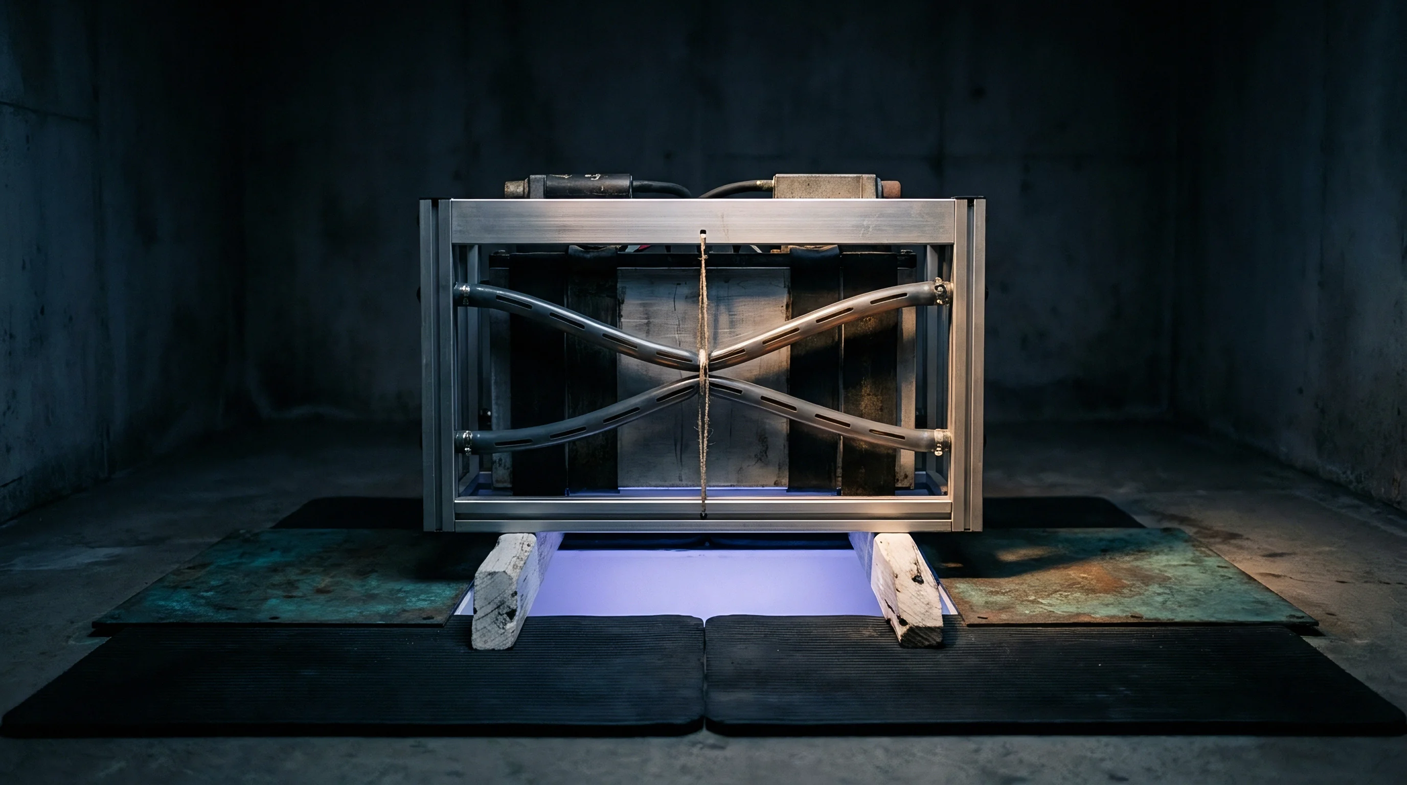
Worked Temperature Elevation Analysis across Relaxed Cooling Boundaries
Take a large-format prismatic cell dissipating 35 W during continuous fast charging against a cold plate with an inlet temperature of 25°C. The interface footprint is 0.06 square meters, bridged by a 1.5 mm interface material rated at a bulk conductivity of 3.0 W/m·K.
At beginning of life, the assembly holds a 0.40 MPa pre-load, where contact resistance measures 0.8 cm²·K/W at each boundary. Dividing nominal thickness by conductivity gives a bulk resistance of 5.0 cm²·K/W. Adding both contact boundaries (5.0 plus 0.8 plus 0.8) yields a total unit resistance of 6.6 cm²·K/W, or 0.00066 m²·K/W. Spread across the 0.06 m² area, overall thermal impedance comes to 0.011 K/W. Under the 35 W heat load, the temperature drop from cell casing to coolant is just 0.385°C, maintaining cell core temperatures within target operating limits.
After eight years of stress relaxation, residual contact pressure falls to 0.04 MPa. Fixed assembly geometry keeps pad thickness at 1.5 mm, leaving bulk resistance at 5.0 cm²·K/W, but boundary contact resistance increases to 4.2 cm²·K/W at each side. Summing these components (5.0 plus 4.2 plus 4.2) brings total thermal resistance to 13.4 cm²·K/W, or 0.00134 m²·K/W, pushing total thermal impedance to 0.0223 K/W. Under that same 35 W load, the temperature differential across the joint widens to 0.78°C. This added thermal barrier elevates cell junction temperatures, compounding capacity loss and driving imbalance between parallel cells.
Maintaining intimate contact across irregular surfaces requires reliable residual clamping pressure over the full pack life.

Modeling
Evaluating multi-year stress relaxation without waiting out empirical aging cycles requires dependable viscoelastic constitutive models. Linear viscoelastic theory relies on spring and dashpot arrangements to simulate time-dependent mechanics. A Maxwell model puts a linear spring and viscous dashpot in series to capture short-term stress decay under fixed strain, while a Kelvin-Voigt model pairs them in parallel to represent transient creep under constant load.
Neither elementary formulation captures the broad relaxation spectra characteristic of cross-linked pad elastomers over decade-long horizons.

Constitutive Equations for Compressive Stress Decay
Generalized Maxwell (Wiechert) representations arrange several Maxwell elements in parallel with an isolated elastic spring. This network structure accounts for short-term segmental motion, intermediate chain untangling, and long-term network rearrangement. Under constant strain, stress decay follows the continuous relaxation spectrum relation:
Stress at time t equals initial strain multiplied by the sum of the long-term equilibrium modulus and individual branch moduli decayed exponentially by time divided by their relaxation times. To cut computational overhead in finite element simulations, analysis often turns to the Kohlrausch-Williams-Watts stretched exponential equation. In this formulation, stress decays from initial stress via an exponential of negative time over characteristic relaxation time, raised to a fractional exponent beta between zero and one.
| Temperature Regime (°C) | Equilibrium Modulus E_inf (MPa) | Characteristic Time Tau (Hours) | Stretching Exponent Beta | Arrhenius Activation Energy (kJ/mol) |
|---|---|---|---|---|
| 25 | 2.45 | 1450 | 0.42 | 68.5 |
| 40 | 1.98 | 420 | 0.41 | 68.5 |
| 60 | 1.32 | 85 | 0.39 | 68.5 |
| Methods note: Parameters derived via dynamic mechanical analysis strain sweeps (0.1% to 5% strain) and static compression stress relaxation tests conducted per ASTM D6147 over 1000 hours. | ||||

Where Does Finite Element Analysis Fail during Multi-Year Relaxation Prediction?
Finite element predictions often diverge when material models calibrated against short-term uniaxial test data are applied to three-dimensional pack assemblies. Thermal interface sheets in battery modules experience near-total volumetric constraint, with cold plates, structural frames, and cell faces preventing lateral flow. Constrained compression alters effective bulk compliance, causing field relaxation behavior to deviate markedly from unconfined laboratory test results.
Time-Temperature Superposition allows short-term relaxation datasets gathered at elevated temperatures to be shifted into master curves spanning decades of service. Using this approach requires confirming that no polymer phase changes or chemical degradation modes occur within the accelerated test range.
- Run static compressive stress relaxation tests across five temperatures from 25°C to 75°C for two thousand hours at each condition.
- Plot compressive relaxation modulus against logarithmic time for each temperature set.
- Establish a baseline reference temperature, usually 25°C, to anchor the curve shift.
- Translate higher-temperature modulus segments horizontally along the logarithmic time axis using shift factors until overlapping regions align.
- Fit the constructed master curve to a generalized Maxwell series or stretched exponential equation to extract operational design parameters.
Whether molecular relaxation under dynamic biaxial strain can be captured using uniaxial static compression data remains an open engineering question.
Settlement
Procurement specifications for thermal interface materials need to govern long-term mechanical response alongside baseline electrical and thermal ratings. Defining bulk conductivity and Shore hardness while ignoring stress relaxation limits leaves pack integrators vulnerable to field degradation. Specifications should mandate minimum retained counter-force across operating temperature ranges over the intended service life of the vehicle or stationary storage system.

Responsibility Boundaries in Thermal Plate Procurement Contracts
Clear responsibility boundaries delineate where cell supplier obligations end and integrator risks begin. Cell manufacturers establish swelling envelopes under specified end-of-life pre-loads, while interface material formulators report compression set and relaxation figures obtained between polished laboratory platens. Integrators design pack enclosure structures, define plate flatness requirements, and set module clamping forces.
| Lifecycle Phase | Primary Responsible Party | Technical Deliverable | Contractual Verification Standard |
|---|---|---|---|
| Cell Swelling Characterization | Cell Manufacturer | Beginning and End-of-Life Volume Profiles | Standardized Life Cycle Compressive Test File |
| Interface Retention Mapping | TIM Material Supplier | 10,000h Relaxation and Creep Master Curves | ASTM D6147 / ISO 815 Compression Set Dossier |
| Plate Surface Flatness | Cooling Plate Manufacturer | Asperity and Profile Tolerance Maps | CMM First-Article Inspection Certificate |
| Interfacial Pressure Retention | Pack Integrator / Buyer | End-of-Life Thermal Resistance Compliance | Pack-Level Accelerated Aging Test Protocol |
Extrusion alters boundary dimensions while friction shifts structural frames, and void formation accelerates local degradation as creep rates double under sustained stress. Because contact pressure governs heat flow across the interface, sourcing terms ultimately dictate liability for thermal degradation.
Section 4.2 of the quality agreement transfers all thermal warranty liability to the pack integrator once incoming pad thickness meets drawing tolerances.

Material Sourcing Checklist for Long-Term Interface Integrity
Integrating thermal interface materials into high-volume pack supply chains demands unambiguous technical requirements within request-for-quotation documents:
- Stress Relaxation Limits define the minimum percentage of retained counter-force after two thousand hours at 60°C under twenty percent nominal compressive strain.
- Volumetric Creep Bounds limit allowable lateral squeeze-out and thickness loss under peak end-of-life cell swelling forces.
- Outgassing Limits set maximum thresholds for total mass loss and collected volatile condensable material under ASTM E595 testing.
- Batch Consistency Proofs require batch-level rheological and thermal conductivity test data before production lots leave the supplier facility.