Quantifying Interfacial Microstructural Phase Transformations and Amortized Tooling Maintenance Limits under Continuous Production
Proactive tool re-dressing at defined stroke thresholds prevents brittle intermetallic growth, optimizing scrap rates and pack manufacturing costs.
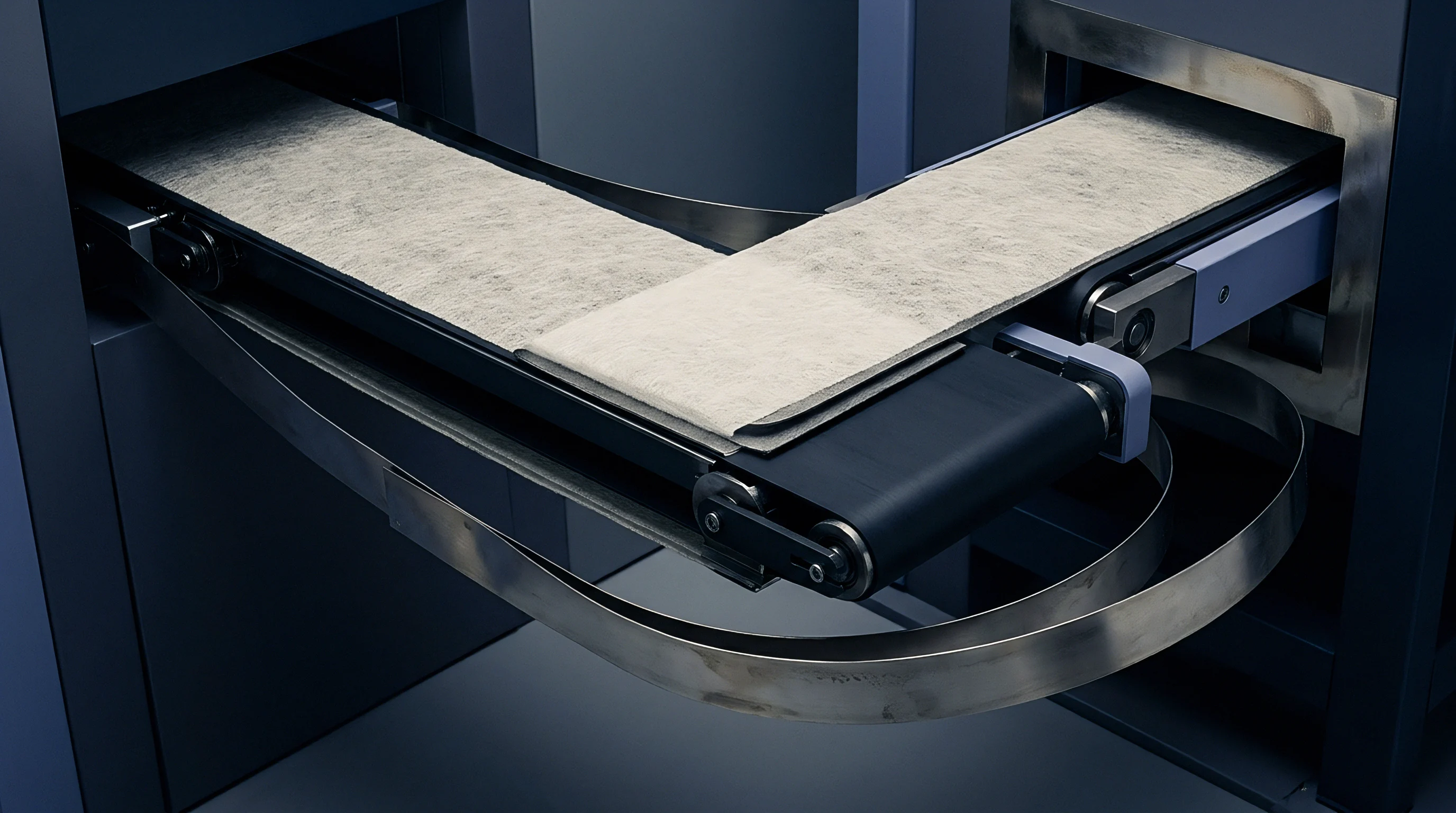

Transformation
A 0.2 mm copper tab strip ultrasonically joined to an aluminum current collector foil under 35 kHz excitation undergoes non-equilibrium phase transformations across the interface during continuous processing. Severe shear strain, localized thermal spikes, and hydrostatic pressure from tool contact drive solid-state atomic diffusion at the junction. During wedge bonding, temperatures at contact asperities regularly exceed 400 degrees Celsius, accelerating mass transport across the boundary.
This localized heat forms brittle binary aluminum-copper intermetallics, including eta-two CuAl2, theta CuAl, and gamma-two Cu9Al4. The volume fraction of these phases determines both the shear endurance and thermal impedance of the joint.
High-rate manufacturing drives interfacial microstructures through a distinct kinetic sequence. Frictional energy disrupts native oxide layers on both metal surfaces, exposing pristine lattice sites. Plastic strain rates exceeding 1000 per second trigger dynamic recrystallization just below the surface, forming fine grains bounded by high-angle interfaces.
These boundaries act as rapid diffusion pathways, driving atomic flux far above static Fickian rates. As a result, intermetallic layers grow continuously during the fraction of a second that welding pressure lasts. Pushing energy input too high or extending tool contact expands this intermetallic zone past design limits.
Phase evolution fundamentally changes joint properties. Clean metallic bonds yield in ductile shear and maintain low contact resistance. Once intermetallic layers exceed a critical thickness of 1.5 micrometers, failure shifts from ductile shear to cleavage fracture along the intermetallic-foil interface.
Because intermetallic compounds are more electrically resistive than pure copper or aluminum, they generate localized ohmic heat under heavy charge and discharge currents. Accumulating these phases elevates joint resistance, forming hot spots that shorten the battery pack’s operating life.
Failure to meet interfacial shear thresholds defined under IEC 62619 invalidates product safety certification and forces a mandatory recall of affected production lots.
Continuous mechanical clamping forces and current transport further complicate phase stability. Steep thermal gradients across the junction during high-current welding induce thermomigration, driving directional atomic movement that accelerates Kirkendall voiding. These sub-micron cavities coalesce along grain boundaries within the brittle intermetallics, degrading overall joint strength.
Controlling these transformations requires tight boundaries on energy delivery, tool geometry, and contact stress across every weld cycle.
Unmanaged phase transformations at tab interfaces lead to specific structural and metallurgical degradation patterns on the line:
- Intermetallic Layer Thickening occurs when excess energy converts ductile interface boundaries into brittle binary copper-aluminum phases.
- Kirkendall Cavitations form when unequal atomic diffusion rates leave micro-voids along the primary shear plane of the joint.
- Recrystallization Softening lowers yield strength in the heat-affected zone of aluminum foils adjacent to the primary weld region.
- Oxide Entrapment traps undispersed alumina fragments inside the weld matrix, creating stress concentration sites that seed fatigue cracks.
Under cyclic acoustic loading, sub-surface dislocation densities multiply rapidly, causing localized strain hardening before thermal recovery can occur. The competition between strain hardening and dynamic thermal recovery determines final grain size and yield strength in the joint. As tooling surfaces wear, power coupling degrades, pushing the process toward either incomplete bonding or localized melting.
Process engineers track the area fraction of soft metallic contact against hard intermetallic coverage to hold parameters within operational metallurgical windows.
Microstructural degradation inside tab welds can pull shear strength below specification, causing interface failure under vibration qualification testing.

Wear
Tool geometry degrades under mechanical fatigue, thermal cycling, and abrasive shear throughout continuous cell production. Ultrasonic sonotrodes, stamping dies, slitting blades, and calendering rolls experience micro-abrasion and plastic deformation on every stroke. Designed with precise pyramidal ridges to transfer acoustic energy into collector foils, a sonotrode knurl pattern suffers pitch decay and tip blunting over long production runs.
Surface erosion reduces grip, causing tool slip and cutting energy transfer efficiency at the weld interface.
Mechanical wear disrupts acoustic coupling between the sonotrode knurl face and the top foil. As knurl tips flatten, friction rises at the tool-foil interface while kinetic friction drops between the foils. This redirects frictional power dissipation away from the joint line and into the tool itself.
Reaching the target bond area then requires higher power inputs, which increases thermal loads on surrounding cell components, accelerates phase growth, and risks tearing thin foil substrates.
| Tool Cycles | Knurl Tip Radius (µm) | Intermetallic Thickness (µm) | Joint Resistance (mΩ) | Defect Rate (%) |
|---|---|---|---|---|
| 10,000 | 12.5 | 0.45 | 0.08 | 0.02 |
| 50,000 | 18.0 | 0.82 | 0.11 | 0.08 |
| 100,000 | 27.5 | 1.45 | 0.19 | 0.42 |
| 150,000 | 42.0 | 2.85 | 0.48 | 2.15 |
| 200,000 | 65.0 | 4.10 | 1.12 | 7.80 |
Slitting blade wear creates parallel mechanical problems during continuous electrode cutting. Tungsten carbide rolls rely on sharp tolerances to prevent burrs along current collector edges. As blade edges round from abrasion, clean shear cutting degrades into tensile tearing, generating high burrs, loose metallic debris, and stress risers along the foil margin.
Edge burrs over 10 micrometers jeopardize separator integrity, raising the risk of internal short circuits in finished cells.
Evaluating sonotrode knurl profiles and executing precision re-dressing procedures follows a strict sequence on the production line:
- Measure the optical profile of the sonotrode knurl face using a three-dimensional laser scanning confocal microscope at four quarter-turn locations.
- Record tip radius, ridge height, and pitch variance against the original manufacturing CAD drawings.
- Compute volume loss on the acoustic driver surface to determine wear velocity per 10,000 production cycles.
- Compare measured parameters against established limits for maximum tip radius and minimum ridge depth.
- Mount the worn sonotrode in a precision CNC wire-EDM re-dressing fixture aligned with original tool datum axes.
- Recut the knurl geometry using single-pass, low-energy discharge settings to avoid thermal cracking in the tool matrix.
- Verify the resonant frequency of the re-dressed sonotrode with an acoustic impedance analyzer to confirm harmonic stability.
Premature knurl degradation and edge chipping often stem from inconsistent foil hardness, variable surface oil residue, and thickness variations across raw material lots rather than defects in metallurgy or tool design.

Diagnostic
Line-mounted sensors capture dynamic feedback during joining, flagging interface degradation in real time. Acoustic emission sensors on ultrasonic actuator stacks track high-frequency vibrational signatures throughout the weld pulse. Shifts in harmonic content and energy decay rates signal slipping at the foil interface.
As tooling flattens, inefficient acoustic power transfer produces spectral shifts that correlate directly with weak bonds and excessive intermetallic growth.
High-speed inline thermal imaging maps temperature distributions across the weld zone instantaneously. Infrared cameras capture peak thermal signatures on every stroke, spotting abnormal localized heating driven by friction fluctuations or tool contamination. Temperatures exceeding process windows point straight to localized phase growth, including runaway aluminum-copper intermetallics.
Linking real-time pyrometry to closed-loop machine controllers enables instant rejection of out-of-spec joints before cells advance to pack assembly.

When Does Microstructural Drift Require Tool Servicing?
Electrical measurements provide high sensitivity for checking joint quality on active assembly lines. Dynamic contact resistance systems inject low-voltage pulses across the stack immediately after mechanical dwell. Shifts in milliohm-level resistance signal incomplete metallic bonding, localized voiding, or thick intermetallic layers.
Combining continuous electrical data with mechanical strain gauge readings creates a detailed diagnostic map for every weld cycle.
Steady baseline resistance reading confirms healthy contact geometry long before visible wear appears on the tool edge.
Selecting appropriate inline non-destructive diagnostic tools requires careful evaluation of measurement speed, spatial resolution, and signal clarity:
- Acoustic Emission Frequency Tracking detects microscopic slip variations and acoustic power dissipation changes indicative of knurl surface wear.
- In-Process High-Speed Thermography captures thermal transients across the bonding area, identifying thermal spikes that trigger intermetallic phase growth.
- Four-Point Electrical Contact Resistance isolates interface resistance from bulk lead impedance to evaluate bond completion.
- Inline Optical Shearography measures elastic surface deformation under mechanical pre-load, highlighting subsurface micro-voids and weak joints.
Tooling degradation alters process physics systematically, leaving distinct signatures across multiple sensing channels. Peak acoustic spectral attenuation at 105 kHz correlates linearly with the growth rate of brittle intermetallic phases in lithium-ion tab joints. Integrating multivariable sensor outputs into predictive maintenance frameworks lets engineers trigger tool replacement based on measured physical drift rather than arbitrary stroke counts.
Questions remain over whether real-time acoustic emission signatures can reliably isolate single-micrometer micro-voids from background factory vibration without heavy filtering routines.

Amortization
Tooling represents a major share of non-recurring engineering and operating expense in high-volume cell production. Advanced materials ~ like ultrafine-grain tungsten carbide, powder-metallurgy tool steels, and monocrystalline diamond coatings ~ carry steep upfront costs. Amortizing these expenses across production runs requires maximizing tool life while avoiding scrap spikes from worn tooling.
Balancing re-sharpening costs, replacement fees, tool life, and scrap yield loss dictates the optimal maintenance interval.
Running tools to failure carries heavy financial penalties in scrap and unplanned downtime. Near mechanical wear limits, joint defect rates rise exponentially. Pushing defective cells through downstream formation, aging, and testing quickly accumulates scrap costs that dwarf the expense of scheduled tool re-dressing.
Maintenance schedules calibrated to wear progression curves establish intervals that minimize landed cost per accepted pack.
| Maintenance Strategy | Interval (Strokes) | Tool Cost / Unit ($) | Scrap Rate (%) | Scrap Cost / Unit ($) | Landed Cost / Unit ($) |
|---|---|---|---|---|---|
| Aggressive Re-dressing | 25,000 | 0.42 | 0.05 | 0.08 | 104.50 |
| Optimized Baseline | 75,000 | 0.14 | 0.12 | 0.19 | 102.33 |
| Extended Life Run | 125,000 | 0.08 | 1.10 | 1.76 | 103.84 |
| Run to Failure | 180,000 | 0.06 | 5.40 | 8.64 | 110.70 |
A rigorous financial model for tooling wear weighs fixed capital expenses against variable scrap rates. Take a facility operating an ultrasonic tab welding cell that produces 1,000,000 packs annually. A premium carbide sonotrode and anvil set costs $12,000 upfront.
Each wire-EDM re-dressing costs $800, with a maximum allowance of five recuts before geometry drops out of specification ~ yielding a total usable lifespan of 450,000 strokes at optimized 75,000-stroke intervals.
Running tools unmanaged extends service to 180,000 strokes without re-dressing. While this lowers direct tooling cost per unit from $0.14 to $0.06, blunted knurl tips increase resistance defects. Accounting for active materials, structural housing, and assembly labor, scrap costs average $160 per defective pack.
Under run-to-failure, defect rates jump from 0.12 percent to 5.40 percent, adding $8.64 in scrap to every pack produced. Operating with worn tooling adds $8.37 per finished unit over a scheduled maintenance program.
Sonotrode re-dressing executed at 75,000 strokes yields an operational savings of $8.37 per pack compared to run-to-failure operation.
Maintaining complete documentation for tooling assets supports quality control tracking and operational cost accounting across manufacturing facilities:
- Tool Serial Number and Batch Traceability File links individual sonotrodes and dies to raw material mill test certificates and coating vendor logs.
- Cumulative Stroke Count and Wear Logbook records total operational cycles, material lot exposures, and recorded actuation pressure metrics.
- Dimensional Metrology and Laser Profile Reports documents original CAD surface baselines alongside periodic scan measurements.
- Maintenance and Re-Dressing Execution Records details wire-EDM recut depths, post-process resonant frequency tests, and surface finish values.
Preventive maintenance schedules deliver the lowest total cost when re-dressing occurs right before scrap rates begin to climb, rather than after quality audits flag defective joints.

Integrity
Joint integrity testing verifies whether welded tab interfaces satisfy mechanical, electrical, and thermal demands over their design life. Mechanical qualification relies on lap-shear and 90-degree peel tests to measure ultimate bond strength. Crisp, sharp tooling produces joints that fail via ductile shear in the base foil.
Worn tooling yields joints that debond along brittle intermetallic boundaries, absorbing less peak force and exhibiting low fracture energy.
Thermal cycling and vibration testing accelerate physical stress on tab interfaces, exposing latent microstructural flaws before cells ship. Under UN 38.3 and IEC 62619 environmental protocols, packs undergo thermal shock from -40 degrees Celsius to +85 degrees Celsius alongside random vibration profiles. Thermal expansion mismatches between pure metals and intermetallics induce cyclic shear stress across the joint.
Micro-voids and Kirkendall cavities created during welding expand under this load, causing mechanical cracking, resistance drift, or open circuits.
| Standard | Test Parameter | Sample Size | Microstructural Acceptance Limit | Electrical Limit |
|---|---|---|---|---|
| UN 38.3 | T3 Vibration (10-200 Hz) | 32 cells | Zero micro-crack propagation across intermetallic layer | Delta R < 5% |
| IEC 62619 | Continuous Thermal Shock | 16 packs | Total intermetallic thickness < 2.0 µm post-test | Delta R < 10% |
| UL 1973 | Drop and Impact Shear | 12 modules | 100% ductile base-metal fracture in lap-shear mode | Delta R < 3% |
Standard qualification procedures mandate specific mechanical shear thresholds and maximum electrical resistance drift allowances for cell interconnects. Under UL 1973 section 12.2, tab-to-busbar interconnects must show zero debonding and maintain less than a 5 percent resistance increase after severe drop and mechanical shock exposure. Quality standards require baseline four-point resistance mapping across all joint interfaces before environmental testing, rejecting any lot with an initial interface resistance spread wider than 0.03 milliohms.
Production protocols mandate sectioning, mounting, and microstructural inspection of sample joints from every lot to verify intermetallic thickness and check for voids.
Standard supply contracts specify that any lot exhibiting more than a 0.05 milliohm resistance jump after 500 thermal cycles triggers full containment, metallographic cross-sectioning, and scrap allocation back to the primary production line.
Governance
Contracts between cell manufacturers, pack integrators, and tooling suppliers must define tooling maintenance limits, scrap liabilities, and quality obligations explicitly. Vague terms around tool ownership and maintenance cause financial friction when audits turn up joint defects. Supply agreements should spell out replacement intervals, dimensional wear limits, and inline monitoring standards, protecting buyers and suppliers alike against scrap disputes and warranty claims.
Clear responsibility relies on reliable floor data. Continuous automated logging of stroke counts, peak ultrasonic energy, and thermal profiles builds a definitive production history. If a lot fails environmental testing from brittle intermetallic fractures, historical logs show whether the defect came from running worn tooling past agreed limits or from raw foil inconsistencies.
Transparent data sharing allows fair allocation of rework costs and warranty liabilities.
Service level agreements with tooling OEMs need explicit performance metrics beyond stroke counts alone. Warranties should specify maximum allowable knurl wear rates, surface hardness values, and dimensional tolerances after re-dressing. If a refurbished sonotrode underperforms under standard operating conditions, the tooling vendor covers recutting, shipping, and line downtime penalties.
Embedding technical specs, maintenance schedules, and quality thresholds into commercial contracts aligns incentives across the supply chain, protecting product reliability and manufacturing yield.