Interfacial Ceramic Coating Adhesion under Multiaxial Dynamic Shear Cycling
Dynamic shear cycling causes separator coating particle shedding, requiring flooded dynamic lap-shear fatigue qualification beyond static peel tests.


Bond

Mechanistic Origin of Interfacial Shear Strength
Ceramic coatings on battery separators provide thermal shrinkage resistance and dendrite suppression at elevated temperatures. Sub-micron inorganic particles, primarily sub-micron alpha-alumina or boehmite, assemble into a porous matrix held together by polymeric binders like polyvinylidene fluoride-hexafluoropropylene or acrylic latexes. Thin polyolefin substrates, constructed from polyethylene or polypropylene via wet or dry extrusion, possess low surface energy.
Adhesion between the ceramic slurry and the non-polar polymer backbone relies on mechanical interlocking, dispersion forces, and corona treatment of the base film. Static adhesion tests fail to reflect the dynamic shear forces encountered inside a operating battery cell. The interface slips.
Binder distribution within the porous alumina network determines the initial toughness of the coating. During the solvent evaporation step on the coating line, volatile carrier removal draws liquid latex or dissolved fluoropolymer toward the outer drying interface. This binder migration depletes the polymer concentration at the substrate interface, creating a weak boundary layer.
Uniform binder concentration throughout the coating thickness maintains interfacial integrity under mechanical stress. Dynamic shear loads target this specific boundary layer, driving micro-fractures along the substrate contact area.
Static 180-degree peel values above 15 N per meter fail to predict coating survival under dynamic shear stresses exceeding 200 kPa.

Polymer Crosslinking and Substrate Wetting Dynamics
Enhancing wet-adhesion requires precise control over solvent surface tension and polymer crosslinking density. Base films treated with atmospheric plasma achieve surface energies above 42 millinewtons per meter, enabling complete wetting by aqueous ceramic slurries. Polyfunctional aziridine or water-soluble carbodiimide crosslinkers react with carboxylated acrylic binders, building a three-dimensional polymer network across the polyolefin film surface.
Unreacted functional groups weaken moisture resistance, while excessive crosslinking reduces binder compliance, causing brittle interfacial cracking during mechanical deformation.
Fluoropolymer binders present distinct adhesion characteristics compared to acrylic systems. Polyvinylidene fluoride homopolymers provide high electrochemical stability against oxidative decomposition up to 4.8 V against metallic lithium. These homopolymers exhibit rigid crystalline domains that resist mechanical shear deformation up to their thermal yield limits.
Copolymerization with hexafluoropropylene lowers crystallinity, increasing flexural compliance and improving wet-peel strength after electrolyte absorption. Electrolyte solvents soften the polymer matrix, lowering the shear modulus of the interface during cell operation.
| Inorganic Mineral | Binder System | Surface Energy (mN/m) | Dry Peel Strength (N/m) | Wet Shear Fatigue Threshold (kPa) |
|---|---|---|---|---|
| Alpha-Alumina (Al2O3) | PVDF-HFP (88:12) | 44.5 | 18.2 | 140.0 |
| Boehmite (AlOOH) | Carboxylated Acrylic | 48.0 | 24.5 | 210.0 |
| Alpha-Alumina (Al2O3) | Water-borne SBR-CMC | 41.0 | 12.8 | 95.0 |
| Boehmite (AlOOH) | PVDF-Acrylic Hybrid | 46.2 | 21.0 | 185.0 |

Cohesive against Adhesive Failure Pathways
Mechanical degradation follows two distinct physical pathways under shear stress. Interfacial debonding occurs when interfacial shear stresses overcome adhesive forces between the binder film and the polyolefin substrate. Particles collect at edges.
Cohesive failure manifests as internal fracture within the porous mineral matrix, leaving binder-rich ceramic residue anchored to the polyolefin surface. Dynamic shear cycling converts localized cohesive micro-cracks into continuous interfacial delamination zones across the separator plane.
Coating suppliers frequently attribute early particle shedding to uncalibrated cell winding tension rather than binder bond fatigue under cyclic anode breathing.
Torsion
Multiaxial Dynamic Stress States during Anode Breathing
Active material volume shifts during lithium insertion and extraction create complex mechanical strain profiles inside sealed battery packs. Silicon-graphite composite anodes expand up to 30 percent along their crystallographic axes during full lithiation. High-nickel cathodes undergo anisotropic lattice changes during high-voltage operation.
These volumetric shifts exert alternating normal compression and lateral planar displacement across the separator interface. Cyclic expansion drives dynamic shear stress along the coating boundary.
In-plane expansion combines with stack-level clamping force to generate multiaxial stress states. Dynamic normal loads squeeze the ceramic coating into the soft polyolefin base, while lateral anode growth drags active material across the ceramic surface. This friction force transmits torsional shear directly through the inorganic particle network down to the adhesive bond layer.
Polymer backbones relax under heat.
- Elastic displacement phase ~ Reversible deformation of binder fibrils occurs during early cycle lithiation without permanent bond rupture.
- Interfacial slip onset ~ Shear stress exceeds local friction limits, initiating micro-scale sliding between anode particles and the ceramic surface.
- Matrix micro-cracking ~ Continuous cyclic shear generates high stress concentrations around mineral agglomerates, initiating inter-particle fracture.
- Delamination propagation ~ Micro-cracks coalesce along the substrate boundary, creating complete coating detachment over active zones.

Shear Displacement Accumulation
Local friction forces vary continuously during dynamic cycling. Fast charging speeds accelerate the rate of anode expansion, driving up strain accumulation rates at the separator interface. Rapid strain rates prevent polymeric binders from undergoing viscoelastic stress relaxation, escalating peak shear stress values.
Tension accelerates crack growth.
Cell swelling creates uneven displacement profiles across large-format battery electrodes. Center regions experience high normal compression that suppresses lateral slip, while unrestrained perimeter edges sustain maximum dynamic shear movement. Dynamic multiaxial testing captures these spatial variations by applying synchronized axial compression and rotational shear to coated separator specimens under realistic electrolyte immersion conditions.
Higher baseline stack pressure suppresses shear slip velocity while accelerating cohesive particle crushing inside unyielding ceramic matrices.

Abrasion

Fretting Failure Modes and Particulate Migration
Continuous dynamic shear cycling induces micro-fretting along damaged ceramic coating interfaces. Loose alumina or boehmite particles break away from the polymer binder matrix and assemble into loose abrasive aggregates within cell jellyrolls. These loose mineral granules migrate under electrochemical potential gradients and thermal convection currents.
Micro-shorts follow coating loss.
Abrasive particles gouge adjacent polyolefin base films during prolonged vehicle vibration or industrial dynamic operation. Thin separator sub-layers, reduced down to 5 or 7 micrometers to maximize energy density, possess narrow mechanical safety margins. Particle indentations decrease dielectric breakdown voltage, establishing localized high-current leakage pathways between opposing positive and negative electrodes.
Clause 6.4 of IEC 62660-2 mandates cell survival under dynamic mechanical vibration without localized internal insulation degradation.

Internal Short Circuit Mechanics under Debris Accumulation
Particulate debris accumulation converts stable ionic conduction channels into localized hot spots. Ceramic particles stripped of binder coating settle inside separator pores, clogging mass transport pathways and concentrating lithium-ion flux into unblocked pore structures. Local current density spikes accelerate lithium dendrite nucleation during cold-temperature high-rate charging sequences.
Yield drops during cycling.
- Abrasive membrane thinning ~ Free hard mineral particles score the delicate polyolefin base substrate during dynamic pack shock loading.
- Binder debris oxidation ~ Detached polymer fragments undergo electrochemical degradation at high cathode potentials, releasing localized gas bubbles.
- Pore channel occlusion ~ Accumulated loose particles restrict ionic conductivity, increasing internal cell impedance across affected active regions.
- Dendrite anchor formation ~ Void pockets left by shed ceramic coatings act as low-resistance paths for dendrite growth through base films.
Inadequate coating shear adhesion transforms micro-fretting debris into localized separator punctures that trigger thermal runaway during high-power field operation.


Bench
Does Dynamic Shear Fatigue Correlate Directly with Static ASTM D903 Peel Strength?
Static ASTM D903 180-degree peel testing measures total fracture energy during steady-state normal delamination at ambient temperature. Dynamic operational environments subject ceramic coatings to repeated multiaxial dynamic shear stress under constrained normal stack pressure inside electrolyte-flooded enclosures. Static peel measurements isolate cohesive tearing or linear peel force, completely omitting viscoelastic fatigue behavior under cyclic shear loading.
Separators demonstrating identical 20 N per meter static peel force show tenfold variances in dynamic shear fatigue life when evaluated under high-frequency lateral oscillation. Static values fail as predictors of operational durability.
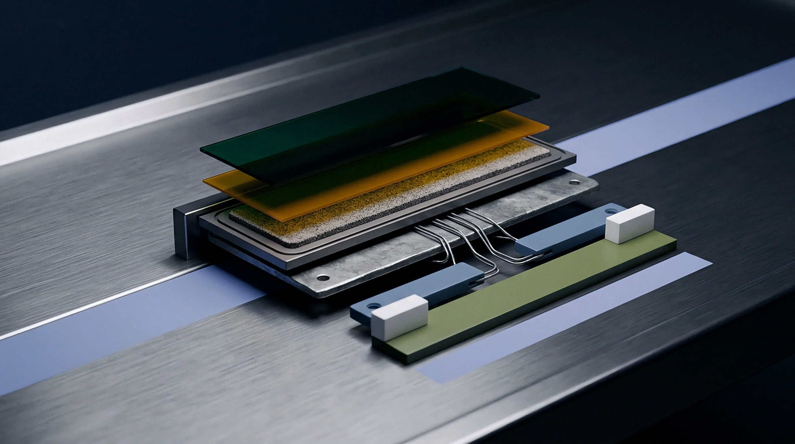
Fatigue life determination mandates direct dynamic shear testing under controlled environmental conditions. Dynamic shear testing rigs mount coated separator samples between planar fixtures, applying calibrated normal preloads while oscillating upper plates laterally at specified frequencies and displacements. Tests run inside temperature-controlled chambers saturated with commercial battery electrolyte simulate real-world pack aging environments.
Acoustic emissions sensors attached to mounting fixtures detect early binder fibril snap events well before macroscopic debonding becomes visible.

Characterization Protocols for Multiaxial Dynamic Shear
Standardized qualification relies on high-resolution force transducers to track real-time changes in shear modulus across dynamic testing cycles. Rapid decay in peak shear stress indicates progressive binder fatigue and internal matrix degradation. Dynamic testing profiles mirror real-world drive cycle profiles, combining steady low-frequency background oscillation with high-amplitude power spikes.
| Test Standard | Stress Mode | Normal Load (MPa) | Frequency Range (Hz) | Primary Output Metric |
|---|---|---|---|---|
| ASTM D903 (Modified) | Static 180° Normal Peel | 0.00 | N/A (Constant Speed) | Peel Force (N/m) |
| ASTM F88 / ISO 11339 | Static T-Peel Strength | 0.00 | N/A (Constant Speed) | Interfacial Toughness (J/m²) |
| Dynamic Lap Shear (Custom) | In-Plane Dynamic Cyclic Shear | 0.10 – 2.00 | 0.50 – 20.00 | Fatigue Cycles to Failure |
| Multiaxial Dynamic Shear | Combined Shear and Compression | 0.50 – 5.00 | 1.00 – 50.00 | Debris Shedding Threshold (Cycles) |
Quality engineers execute specific step-by-step verification procedures to qualify incoming separator batches prior to release into full-scale production lines.
- Submerge five standardized 25 mm by 50 mm coated separator samples into dimethyl carbonate solvent for 24 hours at 25 degrees Celsius to reach swelling equilibrium.
- Mount each conditioned sample into a multiaxial fatigue test fixture equipped with micro-textured contact plates to prevent unbonded surface slippage.
- Apply a constant normal compressive stress of 0.50 MPa to mimic cell module stack pressure.
- Initiate sinusoidal lateral shear displacement at a frequency of 2.0 Hz with an amplitude of 0.20 mm under submerged electrolyte conditions.
- Record real-time dynamic shear force amplitude continuously until shear stress drops 30 percent below baseline values.
- Inspect the active test area using optical microscopy at 100x magnification to quantify particle shedding area percentages.
Section 8.2 of the master quality agreement enforces lot rejection whenever acoustic fatigue monitoring detects particle debonding prior to 50000 shear cycles.


Format

Mechanical Constraint Discrepancies across Cell Geometries
Cell geometric formats govern internal mechanical boundary conditions and spatial strain distributions. Cylindrical cells (such as 21700 or 46800 formats) feature tightly wound jellyrolls constrained by rigid metallic outer cans. Radial expansion translates directly into uniform normal hoop stress, which restricts lateral displacement between adjacent separator and electrode layers.
Cylindrical architectures minimize dynamic interfacial shear movement while escalating localized peak normal compression.
Prismatic cells house tightly stacked or wound electrode groups inside rigid aluminum enclosures. Stack expansion generates non-uniform compressive profiles, characterized by peak forces at core centers and lower constraint along outer perimeter zones. These pressure gradients force soft active material and separator coatings to migrate toward low-pressure regions during charging cycles.
The resulting lateral displacement drives steady shear fatigue along perimeter ceramic interfaces.
| Cell Form Factor | Internal Mechanical Boundary | Dominant Stress Mode | Lateral Displacement Range (µm) | Primary Interfacial Failure Site |
|---|---|---|---|---|
| Cylindrical (21700) | Rigid Radial Constraint | High Normal Compression | < 5.0 | Inner Core Windings |
| Cylindrical (46800) | Rigid Radial / Axial Constraint | Extreme Normal Compression | 5.0 – 15.0 | Tab Proximity Zones |
| Prismatic (Stacked) | Rigid Enclosure / Soft Sides | In-Plane Shear Gradient | 15.0 – 45.0 | Perimeter Electrode Edges |
| Pouch (Laminated) | Flexible Soft Foil Outer Casing | Multiaxial Dynamic Shear | 30.0 – 120.0 | Center Anode Breathing Plane |
Cylindrical gel-roller friction locks separator layers while pouch cell breathing drives continuous transverse edge shear.

Form Factor Impacts on Dynamic Shear Loading
Pouch cells utilize flexible laminated foil outer envelopes that offer minimal mechanical restraint against internal thickness swell. Exterior module plates apply external stack pressure, but thermal expansion and state-of-charge breathing cause planar bending across active surface areas. Unconstrained pouch edges experience high relative lateral displacement during fast-charging dynamic cycles, generating harsh multiaxial dynamic shear environments along coating interfaces.
Pouch cells show edge fatigue.
- Pouch cell selection ~ Specify high-compliance acrylic binders with elongated crosslinking chains to absorb large edge shear movements without debonding.
- Prismatic cell specification ~ Mandate high thermal-stability boehmite coatings with low compression-set characteristics to prevent high-pressure mineral consolidation.
- Cylindrical cell optimization ~ Select ultra-thin ceramic coatings optimized for high shear yield stress to withstand extreme gel-roller winding speeds.
- Module clamping design ~ Align spring-loaded exterior module compression plates to match internal separator coating yield limits over life.
The exact threshold where local binder crosslinking density suppresses macro-shear debonding without restricting ionic transport across thick high-nickel cathode interfaces remains an open empirical challenge.
Claim

Landed Quality Risk Apportionment
Purchasing contracts for coated battery separators must define precise quality boundaries to isolate commercial liabilities. Separator rolls damaged by dynamic shear debonding create massive scrap costs on automated cell assembly lines. Loose ceramic dust clogs vacuum feed lines, contaminates ultrasonic welding anvils, and causes optical inspection systems to trigger false rejection alerts.
Sourcing teams enforce rigid incoming quality limits on ceramic coating adhesion metrics to avoid taking title to defective sub-components.
Tooling and material NRE costs rise when custom slurry formulations are developed for specific high-nickel chemistry pack applications. Supplier quality agreements isolate warranty responsibilities between film coaters, cell manufacturers, and pack integrators. When separator debonding causes field performance degradation, clean technical audit trails determine whether manufacturing defect liabilities rest with the coating line process control or with the cell pack integrator’s thermal management design.
A two percent shift in dynamic shear detachment probability increases field warranty provisioning by 3.80 USD per pack across a 50 kWh production run.

Contractual Warranty Seams and Verification Metrics
A worked financial model illustrates the commercial impact of coating adhesion parameters on total cell manufacturing landed costs. Assume an NMP-free aqueous boehmite coating line running at 80 meters per minute produces 10 million square meters of ceramic-coated separator annually. Baseline raw material and operating production costs average 0.85 USD per square meter.
A baseline failure rate of 1.50 percent driven by edge delamination yields 127,500 USD in direct scrap costs during high-speed cell assembly.
Upgrading the binder formulation with an advanced functionalized acrylic crosslinker increases raw material input expenses by 0.03 USD per square meter, elevating total annual coating production expenditure to 8,800,000 USD. The enhanced multiaxial dynamic shear fatigue resistance reduces cell winding scrap rates from 1.50 percent down to 0.15 percent. Total scrap losses decline from 127,500 USD down to 12,750 USD, producing a net annual operational savings of 84,750 USD.
Reduced field micro-short failure probability yields an estimated 380,000 USD reduction in reserve provisions for pack-level warranty claims.
Quality audit clauses in master supply agreements mandate incoming batch verification via submerged dynamic shear fatigue testing before title transfer occurs at the receiver dock. Certified test reports attached to shipping manifests must verify zero particle shedding across five random sample coupons evaluated under 10000 dynamic shear cycles at 0.50 MPa stack pressure. Non-compliant shipments trigger immediate return-to-vendor protocols at the supplier’s expense, including freight, customs duty, and production line downtime indemnification penalties.