Viscoelastic Solver Integration for Multi Layer Ceramic Separator Thermal Shrinkage
Integrating Prony viscoelastic subroutines into separator shrinkage solvers predicts mechanical stress relaxation and prevents thermal short circuits.
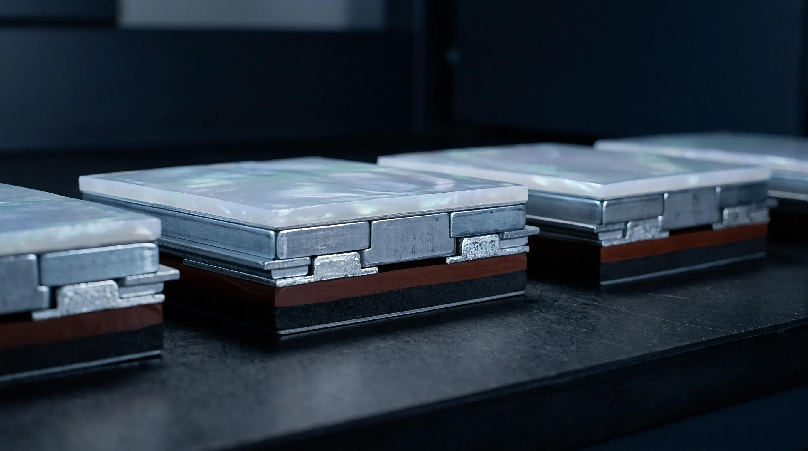

Layer
Polyolefin separators exposed to elevated temperatures show marked anisotropic dimensional instability. Standard thermoelastic continuum models assume linear thermal expansion coefficients and instantaneous spatial recovery ~ assumptions that fail for ceramic-coated battery separators whose mechanical response is governed by a multi-phase composite structure. A typical separator pairs a semi-crystalline microporous polyolefin core, such as wet-process polyethylene or dry-process polypropylene, with a sub-micron inorganic ceramic coating on one or both faces.
Ceramic layers ~ usually alumina or boehmite held in an organic binder ~ add high-temperature rigidity but do not prevent the core from contracting.
Ceramic coatings alter thermal strain response.
Substrate Architecture and Microstructural Anisotropy
Polymer chain networks in polyethylene and polypropylene films reflect their manufacturing route. Dry processing uses monoaxial or biaxial stretching across cold and hot stages to form slit-like pores, aligning chains strongly along the machine direction. Wet processing relies on thermally induced phase separation followed by oil extraction, which produces a more isotropic fibrillar pore network.
Heating triggers entropic recoil in these oriented amorphous regions well below crystalline melting points: polyethylene chains begin relaxing near 80°C, and polypropylene initiates structural relaxation around 110°C. Unconstrained shrinkage occurs mostly along the primary draw axis, causing machine-direction dimensional loss while the transverse direction shows negligible shift or slight outward bowing.
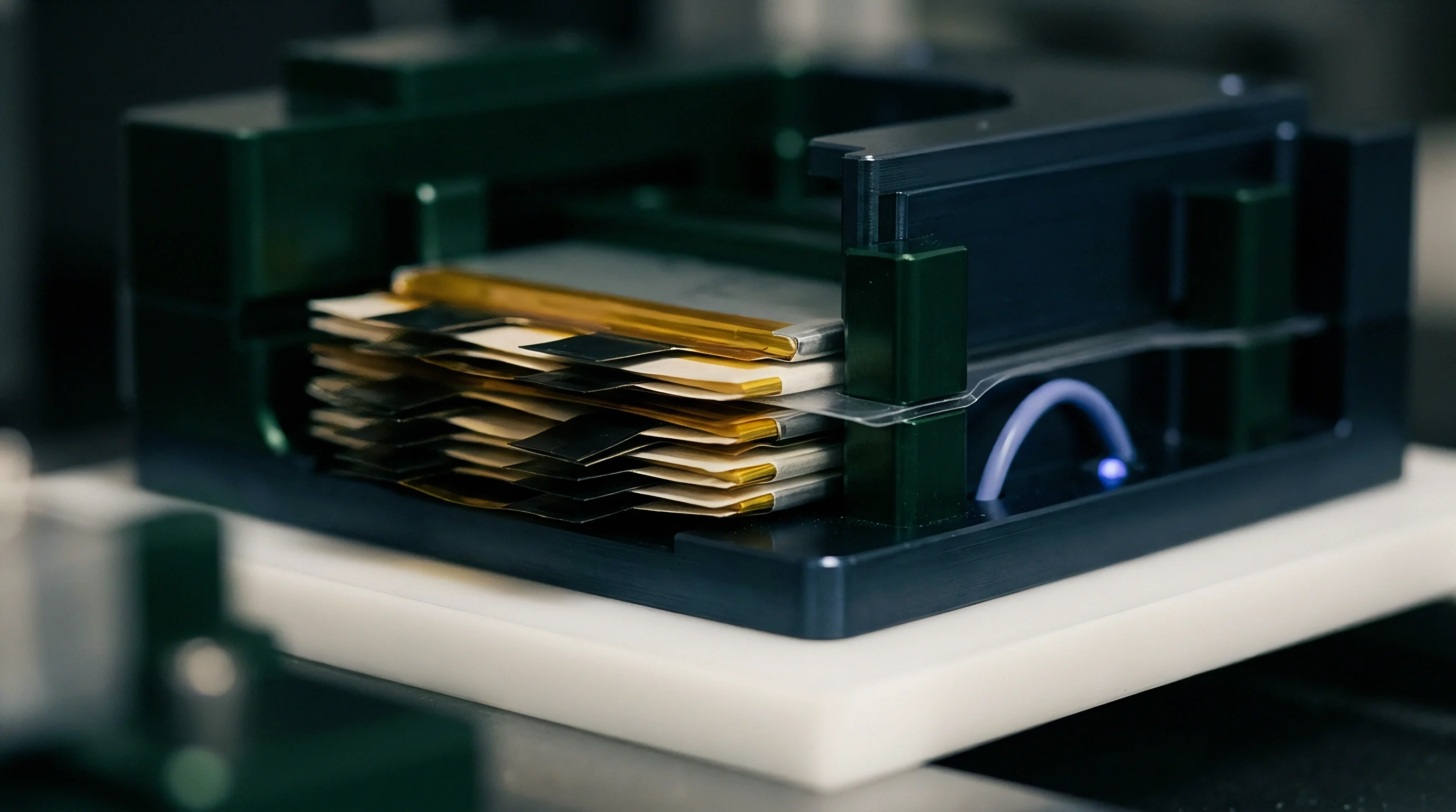
Ceramic Particle Matrix and Binder Coupling
Sub-micron alumina particles held in poly(vinylidene fluoride-hexafluoropropylene) networks modify load transfer across the separator interface. Ceramic particles remain thermally stable with negligible thermal expansion over normal battery operating temperatures (-40°C to 150°C). As heat enters the film, this particle layer forms a rigid skeleton that resists planar compressive loads.
The polymeric binder, however, softens and begins viscoelastic flow. The resulting shear stresses along the interface between the contracting base film and the rigid ceramic layer displace the binder, causing micro-delamination or surface cracks whenever interfacial adhesion drops below critical thresholds.
| Separator Component | Base Material | Thickness Range (μm) | Elastic Modulus at 25°C (MPa) | Softening / Melting Point (°C) | Thermal Shrinkage at 130°C (Unconstrained) |
|---|---|---|---|---|---|
| Microporous Core | Wet-Process Polyethylene (PE) | 5 to 16 | 600 to 1200 (MD) / 400 to 800 (TD) | 130 to 135 | 8% to 25% (MD) |
| Microporous Core | Dry-Process Polypropylene (PP) | 10 to 25 | 1200 to 2000 (MD) / 150 to 300 (TD) | 160 to 165 | 5% to 15% (MD) |
| Ceramic Coating Layer | Alumina (Al2O3) + PVDF-HFP | 1 to 4 (per side) | 3000 to 8000 | 180 (Binder softens ~120) | |
| Ceramic Coating Layer | Boehmite (AlOOH) + Acrylic | 1 to 3 (per side) | 2500 to 6000 | 200 (Binder softens ~110) |
Core thickness dictates the trade-off between cell energy density and mechanical robustness. When the polyolefin core is thinned below 7 μm to maximize active material volume, the ceramic layer governs overall bending stiffness but offers limited resistance against core recoil at elevated temperatures. Deformation across multi-layer separator architectures resolves into four coupled modes.
- Amorphous entropic recoil occurs within the polyolefin substrate as stretched polymer chains return to higher-entropy coiled configurations above the glass transition point.
- Interfacial shear slipping develops between the polyolefin base film and the inorganic coating when thermal stress exceeds the yield strength of the polymeric binder.
- Ceramic frame buckling takes place under high stack pressure when local compressive forces collapse the porous ceramic particle matrix following substrate softening.
- Anisotropic transverse swelling happens perpendicular to the primary contraction axis as mass conservation forces volumetric redistribution in molten core regions.
Ceramic particle distribution density directly controls local thermal stress concentration across the polymer core during thermal transients.
Coating thickness dictates bending stiffness.
Ceramic thermal resistance ratings above 180°C are cited to argue for overall dimensional stability, yet polyolefin core shrinkage occurs below 135°C regardless of surface inorganic coatings.
Relaxation
Capturing the time-dependent mechanical response of polymer separators requires formulations beyond standard linear elasticity. Viscoelastic solvers track both viscous dissipation and elastic energy storage during thermal transients. Shrinkage is dynamic: contraction strains accumulate over minutes or hours depending on heating rates and mechanical constraints.
Models that omit viscoelastic relaxation overpredict internal stresses by roughly an order of magnitude, projecting premature cell collapse or separator tearing where none occurs.
Amorphous PE chains relax rapidly.
Generalized Maxwell Formulations and Prony Expansions
Constitutive modeling uses parallel spring-dashpot networks to capture transient stress decay across logarithmic time scales. Under the Generalized Maxwell formulation, the relaxation modulus is expressed as a Prony series where the time-dependent shear modulus decays exponentially toward a long-term equilibrium value.
Prony parameters fit relaxation modulus curves.
Parameter fitting distributes discrete relaxation times across the relevant experimental window. The transient shear modulus function follows the standard summation:
G(t) = G_infinity + sum from i=1 to N of G_i exp(-t / tau_i)
Here G_infinity represents the fully relaxed equilibrium shear modulus, G_i denotes the relaxation stiffness coefficient for the i-th Maxwell mode, and tau_i defines the characteristic relaxation time constant for that mode. Capturing polyolefin behavior requires five to eight Prony terms spanning 10^-2 seconds to 10^4 seconds. Short time constants dominate during thermal shocks from nail penetration or localized internal shorts, while longer constants govern standard hot-box stability tests.
Time-Temperature Superposition and Shift Functions
Master curves collapse dynamic mechanical data across temperatures using either Arrhenius relationships or the Williams-Landel-Ferry equation. Below glass transition, thermal activation follows Arrhenius kinetics driven by activation energy and absolute temperature differences. Above glass transition, the Williams-Landel-Ferry equation accounts for free-volume expansion:
log10(a_T) = -C1 (T – T_ref) / (C2 + T – T_ref)
Constants C1 and C2 are determined by non-linear regression of dynamic mechanical analysis frequency sweeps run at isothermal steps from -40°C up to the softening point. The shift factor a_T scales physical time to reduced time, accelerating material response calculations within thermomechanical finite element solvers during rapid temperature spikes.
Unimodal relaxation spectra fail to capture polymer melting transitions, necessitating multi-mode Maxwell expansions for high-temperature FEA accuracy.
- Temperature-dependent modulus scaling maps initial elastic stiffness reductions as temperature increases toward core polymer melting points.
- Reduced time integration updates history variables inside individual Maxwell dashpots at every non-linear solver increment.
- Orthotropic Prony spectrum assignment assigns distinct relaxation time sets to machine and transverse directions to account for oriented polymer chains.
- Equilibrium stress floor enforcement prevents numerical energy dissipation from driving material stress state to zero during long isothermal holds.
Applying viscoelastic relaxation parameters derived solely from uniaxial tension tests to complex biaxial cell stack compression states underpredicts transverse thermal deformation.
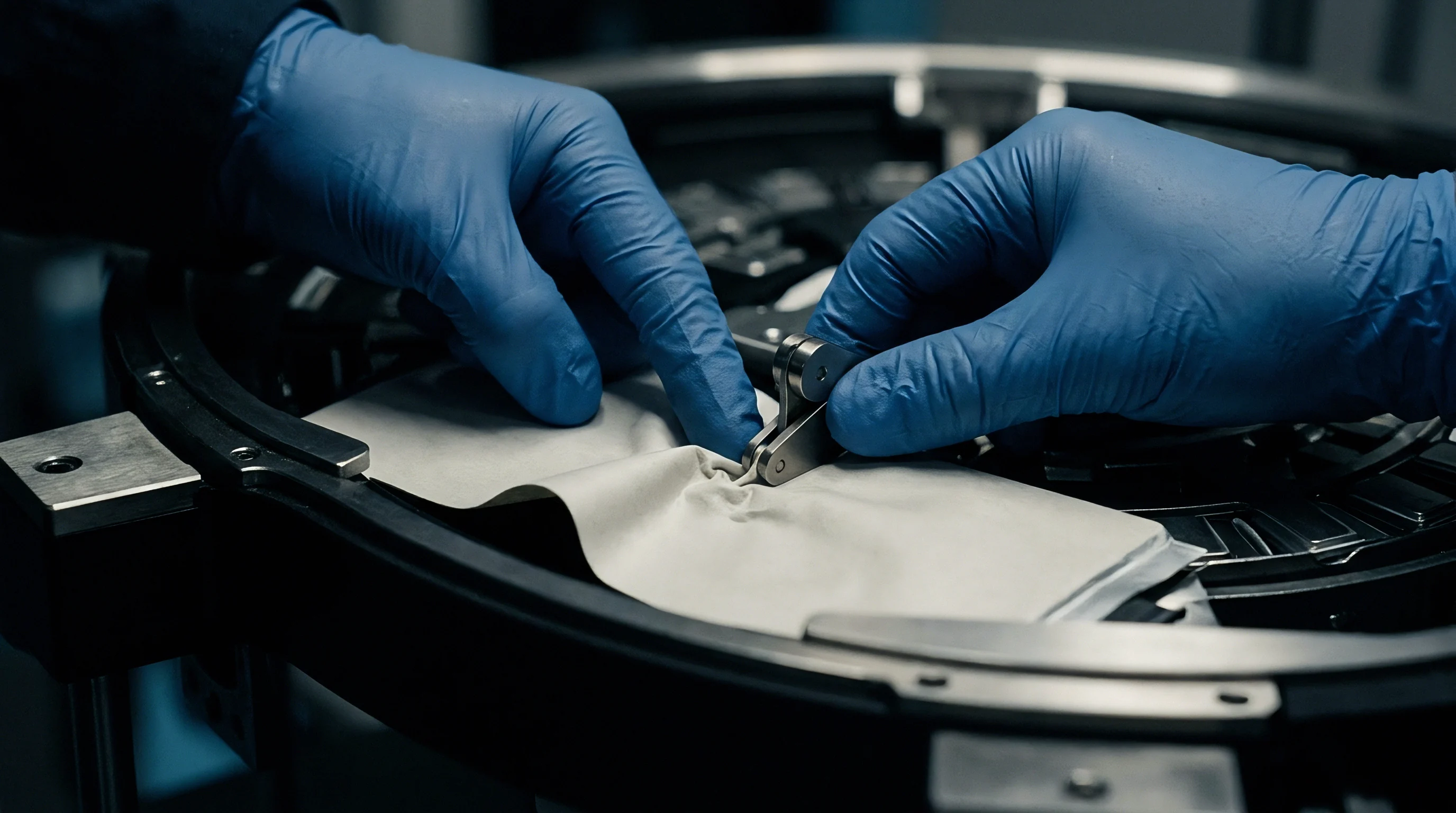
Tensor
Finite element continuum codes update stress states through incremental strain decomposition. Solvers rely on numerical integration algorithms to compute viscoelastic stress tensors at each Gauss point. The total strain rate tensor splits additively into elastic, thermal, and creep components.
Multi-layer ceramic separators present specific numerical hurdles because the ceramic behaves elastoplastically while the polyolefin core is non-linear and viscoelastic-viscoplastic.
Subroutine stiffness matrices mandate spatial symmetry.
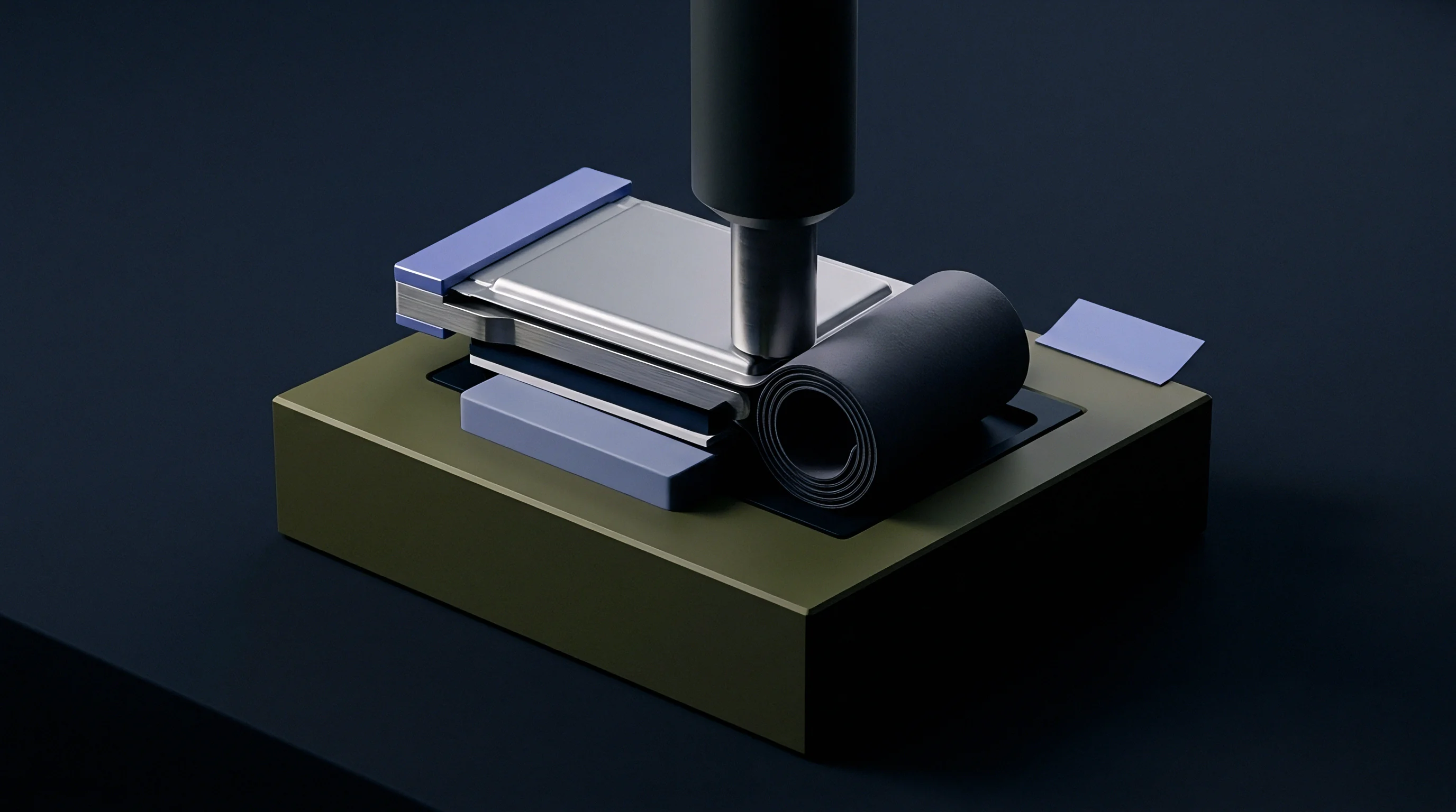
Algorithmic Tangent Moduli and Incremental Strain
Global Newton-Raphson iterations require consistent material Jacobians at each integration point. Thermomechanical subroutines, implemented through user interfaces like ABAQUS UMAT or ANSYS USERMAT, calculate Cauchy stress tensors together with the algorithmic tangent stiffness matrix. Omitting non-linear terms from the Jacobian derivation degrades quadratic convergence, lengthening run times or causing the step to abort.
Thermal expansion remains inherently anisotropic.
Stress updates rely on midpoint algorithms to preserve stability over large load increments. Spatial displacement gradients feed incremental strains into constitutive history variables, updating dashpot state tensors from time t to time t + delta_t.

When Does Numerical Viscoelastic Solver Instability Trigger Artificial Shrinkage?
Time steps larger than the shortest relaxation time in a Maxwell element produce oscillatory stress updates. In explicit thermomechanical runs modeling fast transients, stability depends on step size: if increments exceed tau_min / 2, exponential Prony terms generate negative stiffness states, artificially shrinking the film long before actual thermal thresholds are reached.
Explicit solvers struggle with slow relaxation.
Implicit schemes avoid conditional time-step limits through backward Euler integration, but they require accurate algorithmic tangent tensors. The tangent stiffness matrix must incorporate instantaneous viscoelastic compliance alongside directional thermal expansion coefficients. Orthotropic thermal expansion tensors require three independent principal thermal coefficients aligned with machine, transverse, and normal thickness directions.
Constitutive updating within implicit thermomechanical material subroutines follows a strict sequential algorithm.
- Receive strain increment tensor, temperature increment, and historical material state variables from global solver engine.
- Calculate anisotropic thermal strain increment using directional thermal expansion coefficients evaluated at current step temperature.
- Subtract thermal strain from total strain increment to isolate net mechanical strain increment.
- Update internal state vectors for each Maxwell relaxation mode using exact exponential integration algorithms.
- Sum equilibrium elastic stress contributions and transient Maxwell stress modes to assemble total updated Cauchy stress tensor.
- Construct consistent material Jacobian matrix combining instantaneous tangent shear modulus and thermal expansion derivatives.
- Return updated Cauchy stress tensor, algorithmic tangent matrix, and internal history variables to main solver step.
At 120°C under 0.5 MPa stack pressure, wet-process polyethylene separators lose 12% of initial machine-direction tensile modulus within 300 seconds.
| Solver Integration Scheme | Time Step Control Mechanism | Jacobian Matrix Requirement | Computational Cost per Increment | Shrinkage Strain Precision | Primary Instability Failure Mode |
|---|---|---|---|---|---|
| Implicit Backward Euler | Unconditionally stable (Newton convergence) | Mandatory full algorithmic tangent (C_alg) | High (Matrix inversion per iteration) | High (Smooth integration of stiff Prony modes) | Divergence due to abrupt non-linear softening |
| Implicit Mid-Point Trapezoidal | Conditionally stable based on curvature | Symmetric constitutive Jacobian required | Moderate to High | Very High (Second-order temporal accuracy) | Spurious numerical oscillations at step boundaries |
| Explicit Central Difference | Stable if step | Not required (Diagonal mass matrix) | Very Low per increment | Low to Moderate (Requires tiny step size) | Energy blow-up from under-resolved fast relaxation modes |
Omitting orthotropic thermal strain coupling from the constitutive subroutine results in false convergence that masks local separator buckling during pack thermal ramp events.
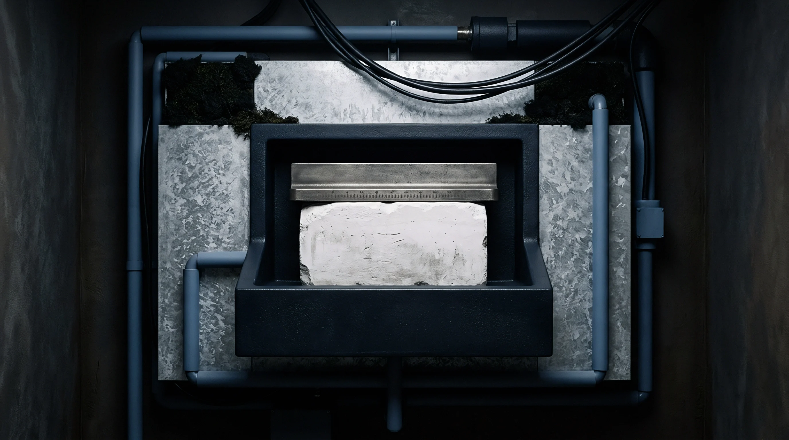
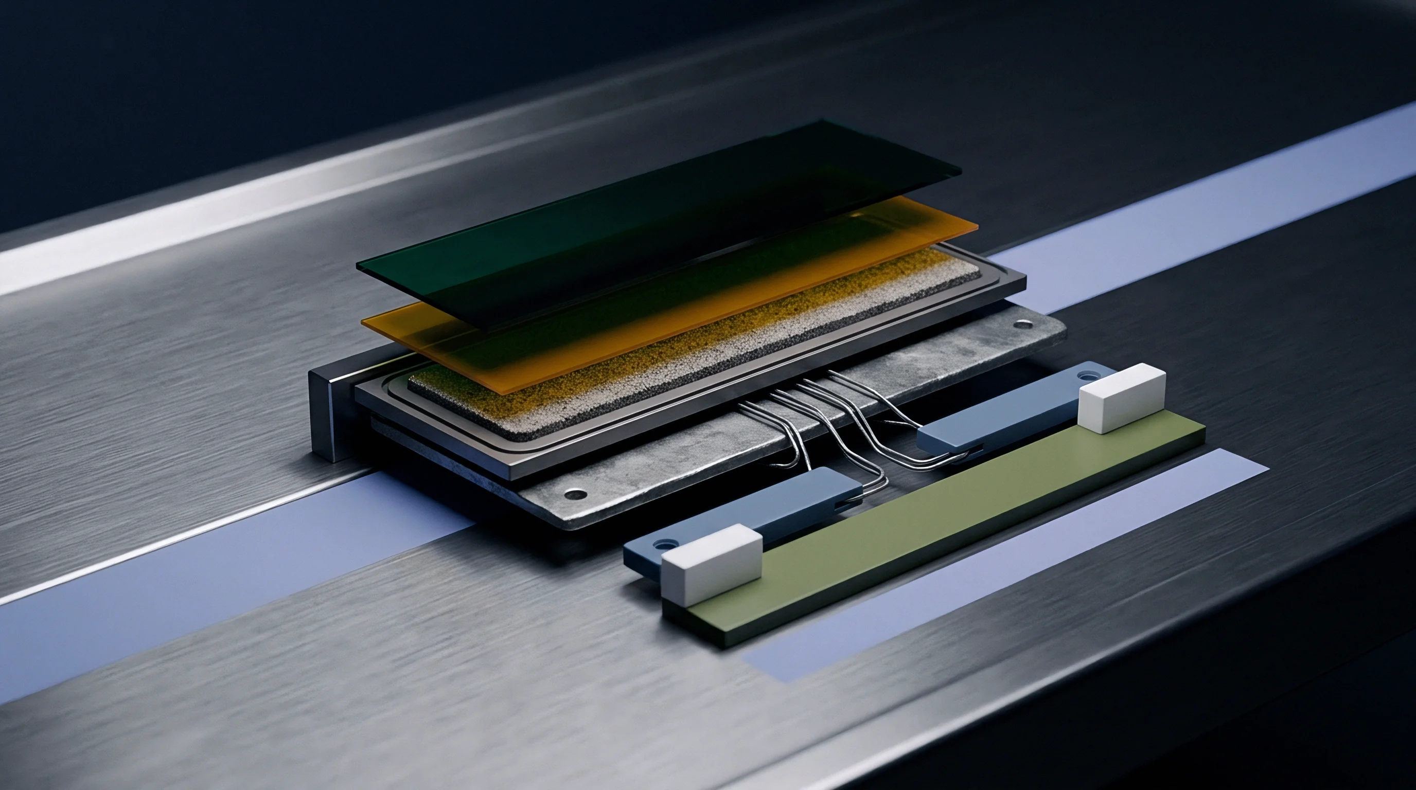
Creep
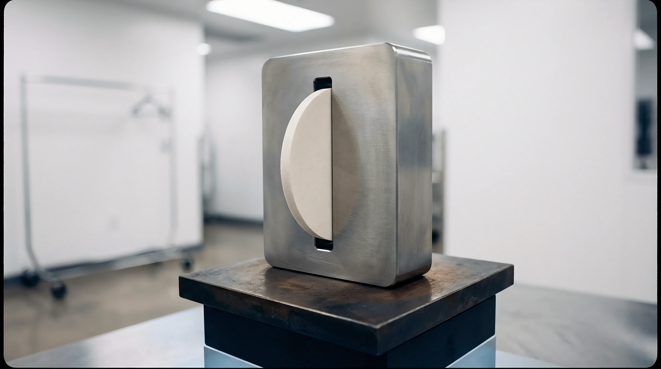
Thermomechanical analysis measures dimensional strain under sustained physical loads. Decoupling creep compliance from thermal expansion is necessary to characterize viscoelastic separator response across thermal cycles. Standard tensile tests fail here: constant crosshead speeds obscure the time-dependent strain that accumulates under low baseline stresses at elevated temperatures.
Static creep testing isolates viscous flow.
Directional Anisotropy and Ratio Measurements
Machine-direction shrinkage consistently exceeds transverse-direction deformation because film drawing aligns the crystalline domains. Dynamic Mechanical Analysis instruments measure storage modulus, loss modulus, and tan(delta) across temperature sweeps from -50°C to 180°C. Isothermal creep tests subject samples to constant tensile loads (0.01 MPa to 0.5 MPa) while tracking axial displacement. Machine-direction specimens show immediate elastic strain followed by primary and secondary creep regimes that accelerate sharply as temperatures approach core melting points.
MD strain drives electrode overhang loss.
Transverse-direction specimens often show negative strain under low initial tension during temperature ramps, widening laterally while contracting along the machine axis. Capturing this orthotropic behavior requires dual-axis Thermomechanical Analysis where machine and transverse displacement sensors record simultaneously in the same thermal chamber.
Stack Compression and In-Plane Restraint Stress
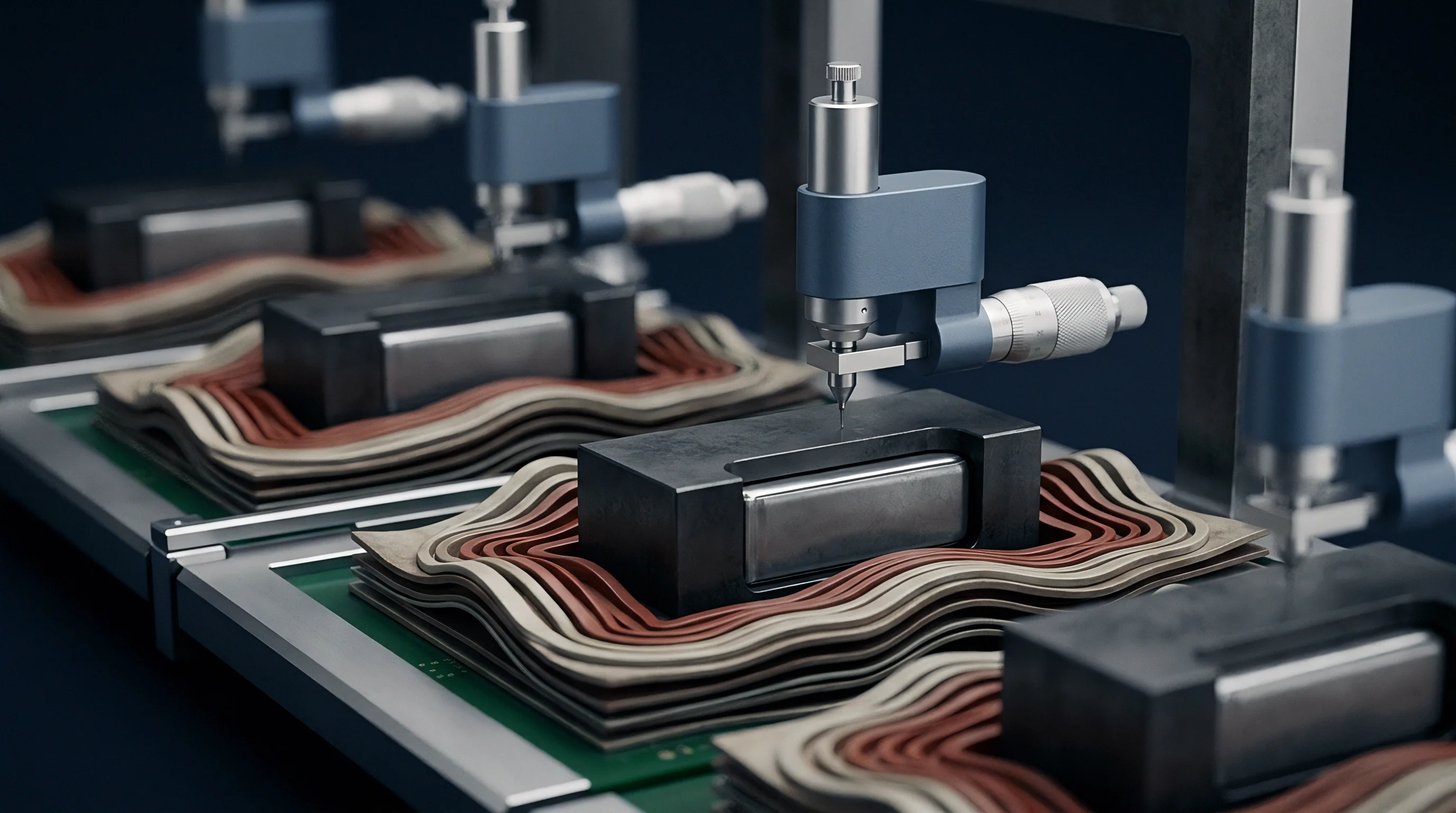
Winding pressure inside the cell limits lateral displacement while generating internal in-plane tension. In prismatic and pouch cells, stack pressure typically falls between 0.2 MPa and 2.0 MPa. When temperature climbs, separator film trying to contract against fixed jellyroll or stack boundaries generates isometric tension.
This internal stress peaks before melting, reaching 1.5 MPa to 5.0 MPa depending on initial winding tension and ceramic coating stiffness.
Orthotropic compliance matrices contain six coefficients.
High internal stress drives stress relaxation. If stack pressure maintains planar constraint, viscoelastic relaxation converts tensile stress into permanent viscous flow without visible macro-scale contraction. However, if local stack pressure drops below critical restraint limits, accumulated elastic energy releases instantaneously, resulting in catastrophic edge contraction.
- Dynamic Mechanical Analysis frequency sweeps establish complex compliance spectra needed to build master relaxation curves via time-temperature superposition.
- Isothermal creep compliance testing measures long-term viscous strain growth under constant compressive stack loads at elevated temperatures.
- Isometric force thermomechanical testing quantifies internal restraint stress generation when film boundaries remain completely locked during thermal ramps.
- Unrestrained thermal shrinkage mapping records maximum dimensional displacement limits under zero external physical constraint per standard factory test protocols.
Compliance with UN 38.3 thermal testing standards demands that separator thermal contraction retains active electrode edge clearance above 1.0 mm.
| Separator Type | Test Condition / Temperature | Applied Constraint / Load | MD Shrinkage Strain (%) | TD Shrinkage Strain (%) | Peak Isometric Tensile Stress (MPa) |
|---|---|---|---|---|---|
| Bare PE (9 μm) | 105°C for 60 min | Unrestrained (0 MPa) | 4.5 ± 0.5 | 0.2 ± 0.1 | N/A |
| Bare PE (9 μm) | 130°C for 60 min | Unrestrained (0 MPa) | 28.0 ± 2.0 | 12.0 ± 1.5 | N/A |
| Bare PE (9 μm) | 130°C ramp (2°C/min) | Fixed Length (Isometric) | 0.0 | 0.0 | 3.8 ± 0.3 |
| Al2O3-Coated PE (9+2 μm) | 105°C for 60 min | Unrestrained (0 MPa) | 1.2 ± 0.2 | 0.1 ± 0.05 | N/A |
| Al2O3-Coated PE (9+2 μm) | 130°C for 60 min | Unrestrained (0 MPa) | 4.8 ± 0.6 | 1.5 ± 0.3 | N/A |
| Al2O3-Coated PE (9+2 μm) | 130°C ramp (2°C/min) | Fixed Length (Isometric) | 0.0 | 0.0 | 1.9 ± 0.2 |
| Al2O3-Coated PE (9+2 μm) | 130°C for 60 min | Stack Compression (0.5 MPa) | 0.8 ± 0.1 | 0.2 ± 0.05 | 0.4 ± 0.05 (Relaxed) |
Meeting the thermal stability clause in IEC 62133-2 Section 7.3.2 modifies separator incoming inspection from simple unconstrained thermal exposure to constrained biaxial load testing.

Yield
Loss of physical separation between positive and negative electrodes marks the thermal safety threshold in commercial cells. Viscoelastic solver integration allows cell designers and pack engineers to trace the loss of physical margin during thermal abuse. When the separator pulls back from active electrode edges, direct contact between anode and cathode triggers rapid electrochemical discharge and accelerates thermal runaway.
Internal stress peaks before separator melting.
Short Circuit Inception and Overhang Depletion
Dimensional retraction that exceeds designed margins allows active anode material to contact coated cathode foil. Manufacturing specifications typically require a separator overhang of 1.0 mm to 2.5 mm past the active electrode edge. Elevated temperatures induce localized shrinkage, and if combined machine- and transverse-direction retractions exceed the overhang margin, electrical isolation fails.
Separator pinholes induce localized micro-shorts.
In-plane shear distributions from viscoelastic continuum models show that corners in prismatic cells carry high biaxial stress concentrations. While central regions remain locked by uniform stack pressure, corners undergo unconstrained relaxation and begin to curl. This edge curl pulls the separator inward from electrode borders even when global shrinkage measurements remain within specification limits.
Hot-Box Thermal Propagation Margin Bounds
Standard abuse testing at 130°C evaluates separator stability during an extended isothermal hold. External heating brings the cell to the polyolefin softening point. Viscoelastic simulations show that initial polyethylene melting closes the pores (the shutdown mechanism) alongside a steep drop in elastic modulus.
The ceramic coating prevents direct electrode contact as long as the binder remains intact throughout this stage.
Predicting thermal safety limits demands exact specification of five coupled thermomechanical design boundaries inside cell simulation toolchains.
- Minimum edge overhang distance defines physical spatial clearance allocated past active electrode boundaries to absorb directional contraction.
- Maximum allowable relaxation stress sets upper thresholds for internal tensile forces generated during isometric stack heating before ceramic coating shear failure occurs.
- Critical binder softening temperature establishes upper thermal limits where ceramic particle matrices lose shear adhesion to polyolefin base films.
- Minimum stack restraint pressure specifies lower compressive limits required across cell winding surfaces to prevent localized edge buckling during thermal ramping.
- Orthotropic thermal expansion tensor limits bound acceptable directional strain differences between machine and transverse orientation axes during transient heating.
Pouch cells face particular vulnerability along perimeter seals where stack pressure falls to zero. Modeling shows that these edges contract first, initiating localized micro-shorts near electrode tabs where high-rate discharge currents generate concentrated heat.
Whether multi-scale phase field solvers can accurately couple local ceramic binder rupture with continuous viscoelastic core shrinkage across full prismatic cell geometries remains an open question.