Modeling Shock Wave Boundary Layer Instabilities in Supersonic Close Coupled Battery Metal Atomization
Supersonic wave instability at the atomizer tip drives melt back-streaming and broadens particle size distribution; stabilizing shock position restores powder yield.


Shock
Gas expanding at the exit of a close-coupled discrete or annular nozzle generates a supersonic flowfield dominated by Prandtl-Meyer expansion fans, compression waves, and intersecting oblique boundaries. High-pressure argon or nitrogen, typically between 2.0 MPa and 4.5 MPa, exhausts into an atomization tower kept near atmospheric pressure. The ratio of stagnation pressure to ambient backpressure drives the gas past Mach 1, creating an over-expanded or under-expanded wave pattern set by nozzle contouring and supply pressure.
As these supersonic streams converge around the central liquid delivery tube, an oblique wave system meets at an acoustic axis downstream of the melt tip. The static pressure established at these wave intersections determines whether molten metal exits cleanly or experiences severe flow reversal.
The boundary layer along the exterior ceramic wall of the delivery tube interacts constantly with this external wave structure. Gas pulled into the low-pressure recirculation zone downstream of the tip forms a wake driven by base pressure dynamics. When an oblique wave striking the tip wall encounters the boundary layer, a sharp adverse pressure gradient strips momentum from the slower fluid near the wall.
Unable to cross this pressure jump, the boundary layer detaches from the solid surface, forming a recirculation bubble right at the melt delivery orifice that shifts the shock foot and triggers high-frequency spatial oscillations.
This coupling between the oblique wave foot and the viscous boundary layer creates a self-sustained acoustic feedback loop. Pressure fluctuations inside the separation bubble travel upstream through the subsonic zone of the boundary layer, moving the separation point and changing the wave reflection angle. This unsteady movement drives pressure oscillations across the melt nozzle face at frequencies between 2 kHz and 25 kHz.
Pressure at the tip swings between positive gauge pressure and negative aspiration; positive spikes easily overcome the ferrostatic head of the molten column, forcing gas bubbles into the melt channel or pushing liquid metal back up the ceramic sleeve.
Gas dynamic regimes in close-coupled nozzles depend directly on plenum pressure ratio and tip recess geometry. Operating below design pressure yields an over-expanded jet with an internal Mach disk and attached separation bubbles, while running above design pressure forms under-expanded expansion fans that push the primary compression wave downstream. Plenum pressure ratios set the supersonic flow regime and pressure stability limits in annular nozzles operating on battery alloy melts.
| Plenum Pressure (MPa) | Pressure Ratio (PPR) | Calculated Exit Mach | Primary Wave Structure | Tip Aspiration Pressure (kPa) | Unsteady Fluctuation RMS (kPa) |
|---|---|---|---|---|---|
| 1.8 | 17.8 | 2.15 | Over-expanded with internal Mach disk | +12.4 | 4.8 |
| 2.5 | 24.7 | 2.48 | Oblique wave reflection with foot separation | -3.1 | 6.2 |
| 3.2 | 31.6 | 2.76 | Balanced expansion with stable focal point | -14.8 | 1.1 |
| 4.0 | 39.5 | 3.02 | Under-expanded with external Prandtl fan | -22.5 | 2.9 |
| 4.8 | 47.4 | 3.24 | Highly under-expanded with secondary shock cell | -18.2 | 8.7 |
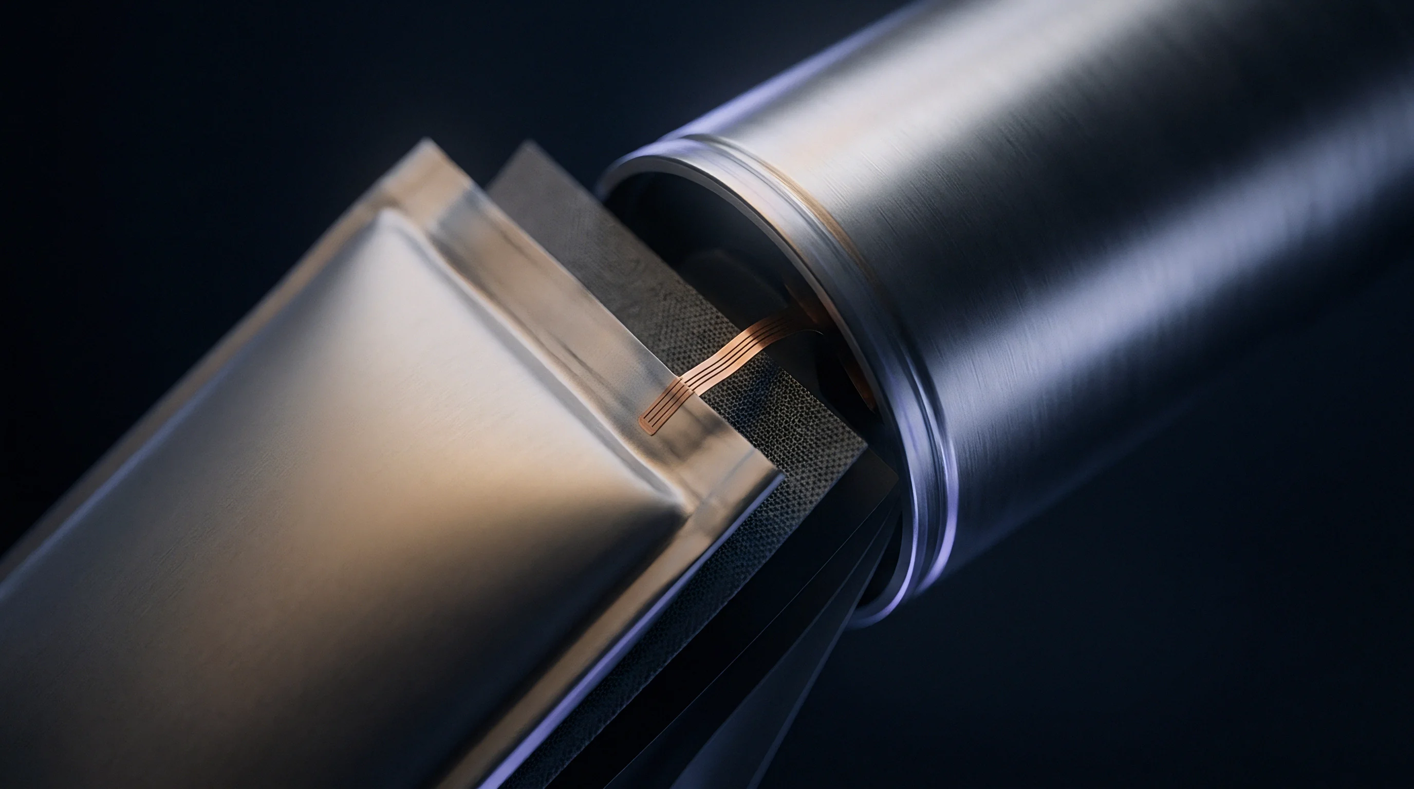
Gas Dynamic Topology at the Atomizer Tip
Shock waves form directly at the nozzle tip.
Converging gas jets create a high-density stagnation zone right ahead of the molten stream. The geometry of the gas sheet forces supersonic filaments to meet the central axis at angles typically between 18 degrees and 35 degrees. This acoustic collision forms a conical wave front that reflects outward toward the jet boundary.
The space bounded by the nozzle exit plane, the outer wall of the liquid tip, and the converging waves forms the recirculation chamber. Base pressure inside this cavity controls melt delivery stability: steady negative pressure pulls melt cleanly into the shear layer, whereas positive pressure swings disrupt delivery.
Where the wave reflects relative to the delivery tube edge determines whether this suction zone remains stable. When the wave foot anchors firmly to the outer corner of the ceramic tip, the separation bubble remains compact and fixed. Off-design pressure ratios cause the shock foot to jump between the tip face and the outer wall, generating strong pressure transients that travel into the liquid orifice.
Operating under an oscillating shock foot produces low-frequency pulsing in the spray, yielding coarse powder fractions and wide particle size distributions.
Argon gas supply pressure variations exceeding 0.05 MPa at 3.2 MPa plenum pressure trigger immediate shock foot relocation and increase particle size variance by 14 percent.
Density gradients in the supersonic jet refract pressure waves and reshape the acoustic field around the liquid stream. High-speed Schlieren imaging shows that small variations in gas temperature or purity alter the local speed of sound enough to shift wave angles. A two-degree shift in compression wave angle moves the impingement point on the central stream by several millimeters.
As that intersection shifts toward the orifice, the local pressure rise restricts melt flow and causes thickness variations in the extruded metal film before primary breakup.

Separation Bubbles and Acoustic Feedback Loops
Boundary layer separation along the delivery tube is driven by adverse pressure gradients from external wave reflections. Friction along the ceramic sleeve saps boundary layer momentum, and when this slowed fluid meets an oblique shock, it reverses to form a stagnant separation bubble. This bubble acts like a physical barrier, turning the supersonic outer flow outward into a secondary compression wave.
Coupling between this secondary wave and the primary jet field establishes an unsteady acoustic loop with frequencies tied directly to tip recess depth.
Recirculating gas within the separation bubble transfers heat from the superheated melt into nearby nozzle components. When running high-melting-point feeds like nickel-rich cathode alloys at 1550 degrees Celsius, this thermal feedback triggers ceramic cracking and orifice freeze-offs. With low-melting-point metals like lithium or sodium alloys operated below 300 degrees Celsius, local gas heating lowers density in the separation zone, altering the local Mach number and acoustic resonance.
Preventing separation bubbles requires matching internal expansion angles precisely to external tube tapers.
Across fifty experimental melt runs, measured pressure fluctuations at the nozzle exit peaked at frequencies matching the second acoustic mode of the gas plenum. This coupling between external shock separation and internal plenum resonance shows that boundary layer behavior cannot be treated in isolation. Unsteady shock movement alters effective throat area, sending acoustic waves back through supply lines into the manifold.
The resulting pressure ripples in the feed lines amplify shock motion at the tip, causing cyclic melt pulsing that reduces powder sphericity and increases satellite formation.
The exact mechanism governing the transition from steady shear atomization to high-amplitude acoustic pulsing remains under active study using high-speed optical diagnostics.
Disruption
Liquid core breakup in close-coupled atomization starts when supersonic gas transfers kinetic energy across the liquid-gas interface. Molten metal exits the central orifice as a continuous cylindrical stream or thin annular sheet. Shear stress from the velocity gap between Mach 2.5 gas and liquid moving below 5 meters per second triggers rapid surface wave growth.
Under steady conditions, small Rayleigh-Taylor waves appear first, followed by rapid Kelvin-Helmholtz growth that shears the stream surface into discrete ligaments. Unsteady wave patterns at the exit disrupt this sequence, introducing sharp pressure pulses that shatter the liquid core prematurely.
Pressure spikes from wave instabilities alter how far the liquid column extends before primary breakup. High aspiration pressure accelerates liquid extraction, thinning the stream and quickening ligament detachment. A sudden positive pressure pulse stops stream elongation, pooling liquid across the orifice face.
When the following supersonic shock front hits this pool, it strips large droplets from the edge through bag-breakup or shear-stripping mechanisms. These oversized primary droplets cool slowly and collide with smaller solidifying particles, creating fused aggregates and irregular shapes that fall outside battery manufacturing tolerances.
Coupling between shock oscillations and the liquid column establishes a specific ligament shedding frequency. When shock foot movement drifts out of phase with the natural capillary instability of the liquid sheet, breakup turns erratic. Large volumes of liquid detach intermittently, stripping energy from the gas stream and lowering local gas-to-metal velocity ratios while the flow breaks down into turbulence.
Wave instabilities during supersonic atomization introduce four distinct primary breakup defects in battery metal streams.
- Liquid Core Stripping Failure occurs when severe positive pressure pulses collapse the aspiration zone, pushing molten metal across the ceramic face where low-velocity gas turns it into coarse, irregular ribbons.
- Orifice Melt Back-Streaming occurs when low-pressure separation bubbles collapse periodically, forcing molten alloy upward along the outer delivery tube wall where it freezes and chokes gas flow.
- Explosive Sheet Disintegration driven by high-frequency shock foot oscillations shatters the liquid film into non-uniform droplets before capillary waves grow to optimal size.
- Ligament Coalescence results when acoustic standing waves hold detached liquid filaments close together, causing droplets to merge before secondary atomization completes.

Coupled Fluid-Acoustic Instabilities
Shear stress drives film detachment.
How unsteady shock fields couple with molten metal depends heavily on melt surface tension and kinematic viscosity. Lithium and sodium alloys have low surface tension and low viscosity, making them vulnerable to high-frequency pressure fluctuations; small acoustic disturbances at the nozzle face quickly amplify surface waves on lithium sheets, tearing them into fine mists almost instantly. Nickel and cobalt alloys, with higher surface tension and viscosity, demand sustained high shear for primary breakup.
In these heavier melts, pressure fluctuations disrupt shear energy transfer, leaving large, incompletely atomized droplets in the spray.
Wave stability determines where secondary breakup occurs downstream of the exit plane. In a stable supersonic jet, primary ligaments enter a secondary breakup region where aerodynamic drag overcomes surface tension, shattering ligaments into sub-50 micrometer droplets. Weber numbers must exceed 100 for sheet breakup and 12 for vibrational droplet breakup.
Unsteady wave patterns lower local Weber numbers by leaving low-velocity wakes behind moving shock fronts. Droplets caught in these low-Weber-number wakes bypass secondary breakup entirely and freeze into oversized particles that degrade final powder packing density.
Droplets passing through turbulent shock wakes experience sudden changes in relative gas velocity, causing boundary layer detachment. As a droplet crosses a shock front, sudden jumps in local density and pressure apply heavy normal stresses across the liquid sphere. If the droplet is not fully solidified, this pressure step flattens it into a disc or strips fluid from its edge.
Droplets flattened during shock passage solidify as oblate spheroids, which pack poorly in electrode slurries and lower volumetric energy density in finished cells.

Shear Stripping and Droplet Shear Mechanisms
Secondary atomization in high Mach gas flows is driven primarily by boundary-layer stripping. Supersonic gas passing over a droplet forms a viscous shear layer across its surface, driving liquid toward the equator where it collects in a thin rim. Aerodynamic drag pulls this rim into fine filaments that snap into secondary micro-droplets.
When external shocks fluctuate, gas velocity over each droplet changes constantly, causing stripping rates to vary wildly across the microsecond solidification window.
Cooling rates during secondary atomization set the final crystal structure of battery precursor materials. Micro-droplets formed by steady boundary-layer stripping cool faster than 100,000 Kelvin per second in high-velocity argon streams. This rapid quenching prevents elemental segregation in nickel-manganese-cobalt (NMC) powders, keeping the stoichiometric uniformity needed for high-voltage cathode performance.
Unsteady shock motion creates pockets of slow gas where cooling rates drop to 1,000 Kelvin per second, allowing phase segregation and dendritic growth that reduce electrochemical capacity.
Consistent aspiration pressure maintains continuous primary liquid core elongation without triggering premature film detachment along the delivery wall.
Maintaining primary shear layer stability requires uniform gas momentum around the entire perimeter of the melt stream. Annular nozzle misalignment or uneven tip wear disrupts this balance, tilting local wave structures. A tilted shock directs higher momentum into one side of the liquid column while leaving the opposite side in a low-speed shadow.
The stream deflects toward the low-pressure side, hitting the ceramic wall or bypassing the high-shear zone un-atomized. Post-run hardware inspections show asymmetric erosion scars where tilted shock fronts pushed molten metal against internal nozzle walls.
Optimizing atomization performance requires aligning gas acoustic dynamics directly with the surface tension and kinematic viscosity of the molten alloy stream.

Computation
Simulating supersonic shock wave-boundary layer interactions requires resolving compressible flow dynamics and multiphase liquid-gas interfaces across broad spatial and temporal scales. Standard Reynolds-Averaged Navier-Stokes (RANS) models fail in close-coupled atomization because their eddy viscosity terms over-damp separation bubbles and wash out high-frequency shock foot oscillations. Accurately predicting unsteady wave motion and base pressure transients requires compressible Large Eddy Simulation (LES) or hybrid Detached Eddy Simulation (DES) formulations that resolve turbulent structures directly.
Compressible supersonic gas modeling relies on numerical schemes that handle steep gradients without introducing numerical artifacts. High-order shock-capturing algorithms, such as fifth-order WENO schemes or momentum-consistent AUSM+ solvers, are applied on unstructured or block-structured adaptive grids. Mesh resolution near the delivery tube surface must fully resolve the viscous sublayer to capture skin friction and wall pressure gradients accurately, requiring a dimensionless wall distance (y+) below 1.0 at the melt tip.
Multiphase interface tracking adds substantial computational overhead. Volume of Fluid (VOF) methods using piecewise-linear interface construction (PLIC) or coupled Level Set methods capture molten column deformation under supersonic shear. However, resolving sub-micron droplet breakup on a pure Eulerian grid requires mesh cells smaller than the droplets themselves, which quickly becomes impractical.
Modern solvers transfer liquid structures from Eulerian VOF to Lagrangian Discrete Phase Models (DPM) once filaments break into discrete droplets, maintaining particle tracking accuracy within reasonable run times.
| Simulation Domain Zone | Spatial Mesh Resolution (µm) | Governing Equations | Turbulence Treatment | Interface Model | Target Courant (CFL) Number |
|---|---|---|---|---|---|
| Nozzle Internal Divergent Section | 5.0 to 12.0 | Compressible Navier-Stokes | Implicit LES / Wall-Modeled | Single Phase Gas | < 0.85 |
| Delivery Tube Wall Boundary Layer | 0.2 to 1.5 (y+ < 1) | Compressible Navier-Stokes | Resolved Viscous Layer | Single Phase Gas | < 0.50 |
| Primary Breakup Recirculation Zone | 1.0 to 3.0 | Compressible Multiphase | Dynamic Smagorinsky LES | VOF with PLIC Reconstruction | < 0.30 |
| Secondary Atomization Far-Field | 15.0 to 50.0 | Compressible Multiphase | Subgrid Stress LES Model | Adaptive VOF to Lagrangian DPM | < 0.90 |

Compressible Governing Equations and Shock-Capturing Schemes
Grid resolution governs shock capture accuracy.
Simulating shock-boundary layer interactions requires solving the full 3D compressible Navier-Stokes equations for mass, momentum, and energy alongside a real-gas equation of state. Compressibility is critical: local Mach numbers regularly exceed 0.3, and gas expansions in the atomizer reach Mach 3.5 as temperatures plunge by more than 150 Kelvin from adiabatic expansion. These density variations tightly couple pressure and velocity, requiring density-based implicit or explicit solvers operating with nanosecond time steps to satisfy Courant-Friedrichs-Lewy (CFL) limits.
Numerical dissipation is evaluated by tracking pressure recovery gradients along the nozzle wall. Low-order schemes or coarse meshes introduce excessive numerical viscosity that artificially pins the shock foot. When shocks are artificially stabilized in a model, calculated aspiration pressures appear steady, masking real instabilities on the melt line.
High-fidelity simulations must demonstrate grid convergence by confirming that shock thickness and separation bubble dimensions remain unchanged across mesh refinement levels.
A four-part verification protocol ensures a solver accurately models shock-boundary layer interaction before findings inform hardware changes.
- Grid Viscous Sublayer Verification requires calculating local skin friction along the ceramic tube wall to ensure the first cell height maintains y+ below 1.0 across all operating gas pressures.
- Single-Phase Wave Validation mandates running gas-only simulations at varied plenum pressure ratios and comparing calculated wave angles against Schlieren optical data to verify shock-capturing precision.
- Acoustic Frequency Power Spectrum Analysis requires recording transient wall pressure history at 100 kHz sampling rates and performing fast Fourier transforms to detect non-physical numerical damping.
- Multiphase Coupling Boundary Setup ensures interface surface tension forces and pressure jumps match Laplace-Young analytical limits before initiating liquid metal extrusion into the supersonic domain.

Multiphase Interface Tracking under Unsteady Pressure Gradients
Modeling molten metal breakup requires balancing surface tension forces against strong aerodynamic shear. Battery alloy melts span wide surface tension ranges, from 0.4 N/m for pure lithium to 1.8 N/m for cobalt-rich precursors. Accurate force balances depend on precise local curvature calculations; standard VOF schemes often generate spurious interface velocities from poorly resolved surface tension gradients.
Combining continuous surface force (CSF) formulations with sharp-interface level-set filters suppresses these numerical artifacts, yielding realistic capillary wave growth under shock excitation.
Coarse meshes smooth out real shock structures.
Shock foot movement creates local pressure gradients across the melt interface exceeding 100 MPa per meter. These steep gradients distort the liquid surface faster than surface tension can smooth it out. Algorithms must track this rapid surface tearing while enforcing strict mass conservation.
Conservative volume tracking prevents artificial mass loss as liquid filaments thin, keeping calculated powder yields within 1.5 percent of actual batch weights.
Predicting phase transformations in atomized droplets requires coupling thermal transport directly to the fluid dynamics solver. As micro-droplets separate from the liquid column, convective heat transfer surges under supersonic relative gas velocities. Solidification models must account for undercooling, latent heat release, and solid fraction growth rates.
In reliable simulations, the droplet surface heat transfer coefficient updates dynamically based on local Knudsen and Reynolds numbers, capturing thermal shielding in the wakes of leading droplets.
Failing to capture transient shock oscillations in multiphase simulations underestimates primary droplet breakup energy, leading to undersized gas plant specifications and frequent melt line freeze-ups during production.

Geometry
Suppressing shock-boundary layer instabilities in close-coupled atomizers depends heavily on nozzle geometry and delivery tube profiling. Converging-diverging (De Laval) gas channels require tight manufacturing tolerances to prevent parasitic internal shocks. If the divergent section strays from the target expansion profile by more than 0.02 millimeters, internal oblique compression waves form in the throat.
These waves exit the channel at angles that disrupt the external flowfield and trigger premature boundary layer separation along the central tube.
The axial offset between the ceramic tip and nozzle exit plane sets the tip recess length. Moving the tip upstream into the plenum changes recirculation chamber volume and shifts base pressure dynamics. A deep recess shields the liquid column from initial supersonic shear, allowing it to spread across the ceramic face before encountering high-velocity gas.
Extending the tip downstream past the exit plane places the orifice directly in the supersonic core ~ maximizing shear, but exposing the tube to severe thermal shock and wave impingement. Setting the correct tip position determines whether shock oscillations damp out or grow during atomization.
The apex angle of the delivery tube tip controls how incoming gas interacts with the boundary layer. Tapering the outer wall to an acute angle between 15 degrees and 22 degrees minimizes adverse pressure gradients as supersonic gas sweeps over the ceramic surface. Steeper apex angles force gas to turn sharply, generating strong compression shocks at the ceramic corner that induce immediate boundary layer separation.
Inspecting atomization tips for battery metal production requires specific geometric verifications.
- Ceramic Wall Convexity Inspection verifies that the outer delivery wall maintains flat or concave profiles, preventing localized expansion fans that destabilize shock foot attachment.
- Gas Exit Radius Measurement confirms nozzle edge chamfers remain below 0.05 millimeters to maintain crisp flow separation without introducing acoustic noise.
- Concentricity Alignment Verification ensures the liquid delivery tube centers within the gas annulus within 0.015 millimeters to balance circumferential wave forces.
- Tip Recess Depth Calibration sets the exact axial offset between ceramic face and gas exit plane using precision micrometer shims to control aspiration chamber volume.

Delivery Tube Tip Profiles and Apex Geometry
Internal nozzle contours shape external flow fields.
Machining ceramic delivery tips demands diamond tooling and tight process control. Alumina, zirconia, and boron nitride are standard refractory choices for battery metal sleeves due to their resistance to molten lithium and nickel alloys. Grinding operations routinely leave micro-grooves along the apex taper, however.
These micro-grooves act as roughness elements that trip the laminar boundary layer into turbulence and change local skin friction. While a turbulent boundary layer resists separation slightly better under mild pressure gradients, it increases conductive heat transfer from the recirculation zone back into the ceramic sleeve.
Profiling ceramic wall tapers requires balancing aerodynamic boundary layer management against thermal insulation needs. Thin-walled tips minimize aerodynamic disturbances and lower shock foot oscillation amplitudes, but lack mechanical strength and experience high heat loss. Thermal dissipation into cold supersonic gas freezes melt at the orifice lip, forming skull buildup that distorts the exiting liquid film.
Thick-walled tips provide better insulation but present a blunt face to the gas, expanding the base recirculation chamber and raising sensitivity to acoustic pressure swings.
Nozzle hardware manufacturing contracts must mandate maximum circumferential exit radius deviations under 0.010 mm; exceeding this tolerance invalidates tip stability guarantees and shifts performance liability to the machining vendor.
Pressure transients destabilize the liquid core.
Adding mechanical vortex generators or acoustic micro-cavities along the exterior delivery wall offers a physical route to stabilizing boundary layer separation. Machining tuned acoustic slots into the ceramic sleeve alters the natural frequency of the base cavity, breaking phase alignment with plenum pressure transients. These passive dampers absorb energy from oscillating shock feet, reducing peak pressure amplitudes by up to 60 percent.
Vortex generators redistribute boundary layer momentum, helping flow navigate adverse pressure gradients without detaching from the tip face.

Can Recessed Delivery Tips Eliminate Shock Instability?
Recessing the delivery tip into the plenum alters acoustic reflections in the base cavity, damping certain oscillation modes while introducing new thermal boundary conditions. Moving the tip back forms a semi-enclosed cavity bounded by the ceramic wall and internal nozzle throat that acts as a Helmholtz resonator. When sized correctly, this cavity traps high-frequency pressure waves from shock foot motion, preventing acoustic feedback from reaching the liquid orifice.
Tip recessing also alters thermal coupling between the gas jets and the melt. Inside the plenum, lower gas velocities reduce convective cooling along the ceramic sleeve. This warmer profile keeps low-melting-point alloys like sodium or lithium liquid right up to the detachment line.
At the same time, elevated plenum temperatures reduce gas density in the cavity, shifting sound speed and altering the acoustic resonance frequency. Recess depths must therefore be tuned to the operating temperature of the specific alloy being atomized.
High plenum pressure suppresses wake flow reversal.
Proprietary tip designs rarely eliminate boundary layer separation or wave oscillations entirely. When atomization runs yield coarse powder or suffer back-streaming freeze-ups, liquid head fluctuations or feed contamination are often cited rather than shock instabilities inherent to nozzle geometry.


Grain
Battery powder specifications require tight control over particle size distribution, sphericity, and satellite counts. Nickel-rich cathode precursors, solid electrolytes like LLZO (lithium lanthanum zirconium oxide) and LPSCl (lithium phosphorus sulfur chloride), and metallic lithium foil feeds all demand narrow particle distributions. For solid electrolyte sintering, powders require a d50 between 15 micrometers and 25 micrometers with a d90 under 45 micrometers to achieve target green densities during tape casting.
Coarse fractions over 53 micrometers create void networks during pressing that promote lithium dendrite growth and cause internal shorts in finished cells.
Shock-boundary layer instabilities widen particle size distribution, reducing usable powder yields. Stable supersonic atomization produces a tight log-normal distribution with high recovery in the target battery range. When the shock foot oscillates, unsteady energy transfer creates a bimodal distribution of fine micro-satellites mixed with oversized droplets.
Sub-5-micrometer fines oxidize quickly during handling, while coarse fractions require sieving or jet milling steps that can introduce contamination into the batch.
Inert gas consumption dominates operating costs in battery powder atomization. High-purity argon delivered at 15 to 40 cubic meters per minute accounts for up to 65 percent of total processing cost per kilogram of powder. Increasing the gas-to-metal ratio (GMR) can overcome shock instabilities through raw kinetic energy, but the gas consumption quickly becomes uneconomic.
Stabilizing the flow aerodynamically allows operation at lower gas pressures while maintaining fine particle yields, directly improving production margins.
| Battery Material Application | Atomizing Gas Medium | Gas-to-Metal Ratio (kg/kg) | Target Size Fraction (µm) | Target Yield Efficiency (%) | Satellite Particle Count Index | Argon Cost per kg Powder (USD) |
|---|---|---|---|---|---|---|
| High-Nickel NMC Cathode Precursor | High-Purity Argon | 2.8 | 15 to 35 | 68.5 | Low (< 5%) | $3.45 |
| Solid State LLZO Electrolyte Feed | Ultra-Pure Argon | 4.2 | 5 to 20 | 52.1 | Moderate (8-12%) | $5.80 |
| Lithium Metal Anode Alloy Powder | Specialty Nitrogen/Argon Blend | 1.9 | 20 to 45 | 74.2 | Very Low (< 3%) | $1.95 |
| Silicon-Copper Anode Current Collector | Technical Argon | 2.4 | 10 to 30 | 71.0 | Low (< 4%) | $2.85 |

Satellite Particle Suppression and Solidification Dynamics
Satellites form when fine, solidifying droplets get pulled into the recirculation wake behind an unsteady shock and weld onto larger, slower liquid drops. In electrode processing, satellited powders raise slurry viscosity, lower packing density during calendering, and lead to uneven current distribution across the active layer. Suppressing boundary layer separation collapses this turbulent wake, carrying fine particles downstream away from freezing primary droplets.
Powder yields drop sharply under acoustic oscillation.
High cooling rates maintained by stable supersonic flow lock in target crystallographic phases. In lithium alloys, rapid quenching suppresses macro-segregation and maintains stoichiometric uniformity across every particle. When shock oscillations disrupt gas velocities, convective cooling drops intermittently; the resulting slow-cooled particles develop coarse grain boundaries and surface oxides that hinder lithium-ion transport, reducing initial coulombic efficiency in active cell components.
Satellite particles degrade final packing density.
Spherical morphology ensures consistent flow during automated electrode manufacturing. Irregular particles, teardrops, and fused aggregates increase inter-particle friction, causing hopper bridging and uneven thickness in solid-state pressing dies. Dynamic image analysis shows that atomization runs plagued by strong shock oscillations produce particle aspect ratios below 0.82, whereas stable runs maintain sphericity values above 0.94 across the entire target size band.

Receiving Inspection and Qualification Standards
Incoming inspection of atomized battery powders requires checking particle size distributions, morphology, chemical purity, and phase composition. Quality control protocols must enforce tight statistical bounds before accepting shipments from external atomization suppliers. Standard verification before electrode slurry preparation follows five quality steps.
- Sample three representative powder canisters from each master lot using an automated rotary riffler under a dry argon atmosphere.
- Measure particle size distribution using laser diffraction per ASTM B822 standards, verifying that d10, d50, and d90 limits match drawing specifications.
- Perform dynamic image analysis on a minimum of 50,000 individual particles per sample to quantify sphericity and satellite attachment frequency.
- Quantify interstitial gas impurities including oxygen, nitrogen, and hydrogen using inert gas fusion per ASTM E1019 protocols.
- Conduct X-ray diffraction analysis to confirm phase purity and verify that rapid solidification quenching successfully suppressed crystalline phase separation.
Argon consumption represents the primary operating expense.
Yield losses compound hardware tooling costs.
Procurement specifications should establish enforceable quality limits on incoming battery powders, linking payment release directly to yield metrics. Standard supply contracts dictate that if the target particle size fraction falls below 65 percent of total batch weight or satellite indices exceed 8 percent by count, the buyer may reject the entire lot at the vendor’s expense.