Mechanical Reference Alignment in Battery Swelling Test Channels
Mechanical reference alignment in swelling test channels requires frame compliance compensation and invar sensor arms to eliminate micrometer displacement errors.


Datum
Pouch and prismatic cells expand along their thickness axis during cycling, generating forces above five kilonewtons in constrained test channels. Without a mechanically invariant zero plane, displacement transducers record a mix of electrochemical cell growth, fixture deflection, and thermal expansion of the mounting hardware. Isolating true dimensional change requires an unyielding baseline reference surface before applying mechanical load.
Primary Mechanical Reference Planes
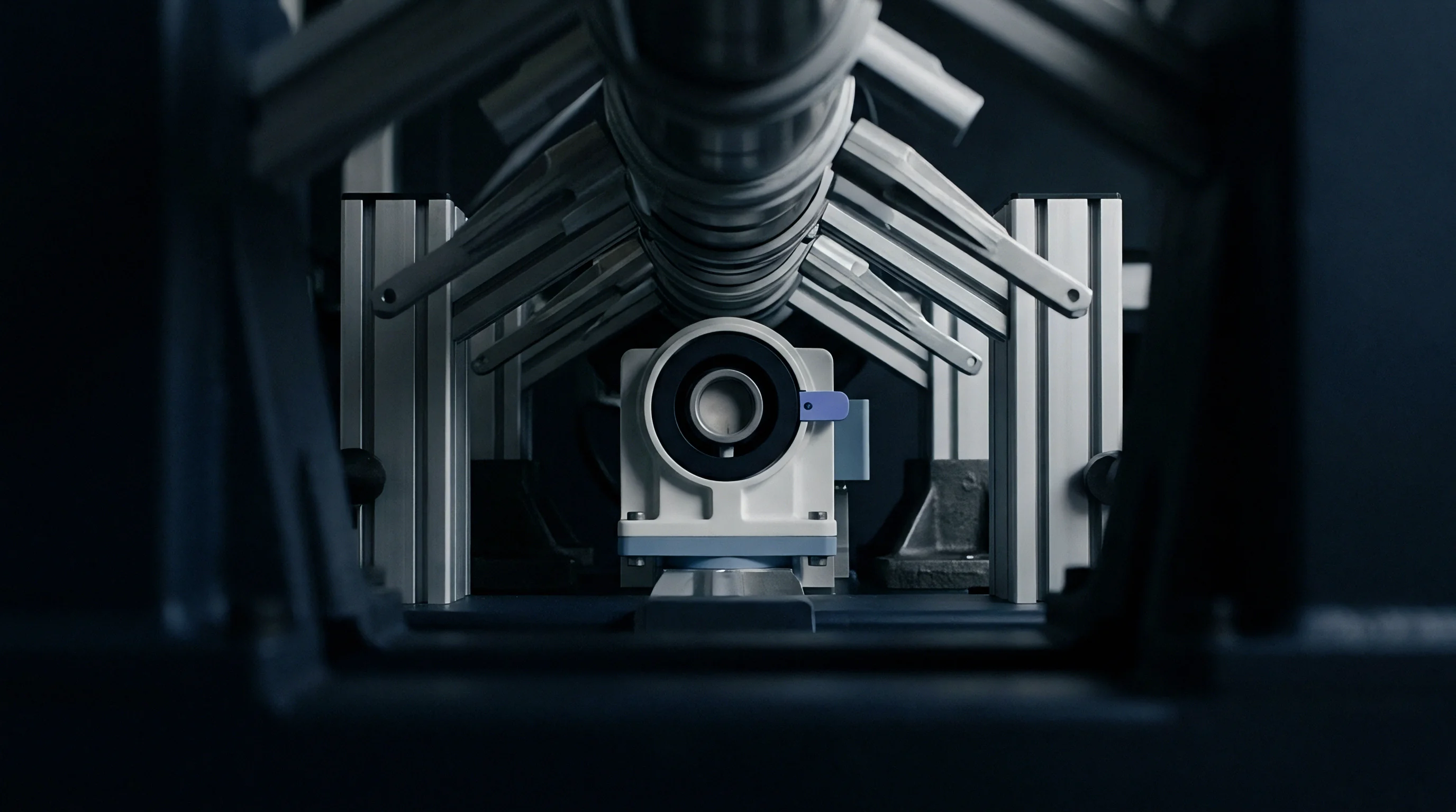
Establishing a fixed physical boundary relies on a heavy ground steel platen flat within five micrometers across its working surface. Ground silicon nitride ceramic plates provide even greater dimensional stability than hardened steel because of their higher elastic modulus and near-zero coefficient of thermal expansion. This stationary reference face serves as the origin point for all linear displacement sensors around the channel perimeter.
Parallelism between the fixed reference platen and the moving load plate dictates force distribution across the cell faces, where alignment errors concentrate mechanical stress.
Thermal Drift in Displacement Reference Fixtures
Ambient laboratory temperature fluctuations alter frame dimensions during long-term cycling trials. A steel fixture rod spanning two hundred millimeters expands by two point four micrometers for every one degree Celsius temperature rise. In temperature-chamber swelling tests cycling between minus twenty and sixty degrees Celsius, uncompensated metallic sensor brackets create baseline errors that exceed the actual breathing magnitude of fresh lithium-ion cells.
Invar alloys, with thermal expansion coefficients below one point five times ten to the minus sixth per Kelvin, preserve sensor mounting geometry across wide environmental sweeps.
Minor sensor mounting shifts are sometimes treated as ordinary laboratory ambient noise that leaves a cell’s initial swelling slope unaffected.


Rig
Test channels maintain battery cells under precise mechanical boundary conditions while measuring thickness changes down to single micrometers. Multi-axis test rigs integrate high-precision linear bearings, load cells, and contact or non-contact displacement sensors to evaluate pouch and prismatic expansion profiles under constant gap or constant pressure conditions.

Transducer Mounting Vectors and Spatial Alignment
Linear variable differential transformers capture face expansion along the central centroid axis. Mounting displacement sensors off-center introduces cosine errors and moment arm distortions when cells expand unevenly. Single-point displacement measurements cannot distinguish uniform swelling from localized pouch gassing or plate tilting, whereas arraying three sensors in a triangular pattern across the compression plate reveals face angular tipping alongside absolute thickness growth.
Cell expansion exerts significant mechanical strain on the surrounding fixture housing.
A two-micrometer misalignment across a hundred-millimeter platens face introduces an artificial twelve percent error in measured end-of-life pouch cell expansion.

Guide Rail Friction and Angular Binding
Linear bearing resistance creates artificial load spikes during rapid cell volumetric growth. As a cell expands against a spring-loaded or hydraulic pressure plate, side thrust forces generate friction that impedes smooth plate movement. High rail friction holds back true cell expansion until internal mechanical stress overcomes static friction, releasing in sudden stick-slip displacement jumps that corrupt continuous swell curves.
Recirculating ball linear guides operating with low pre-charge minimize stick-slip motion, maintaining smooth axial movement under off-center loading.
| Transducer Type | Measurement Resolution | Thermal Sensitivity | Mechanical Loading Impact |
|---|---|---|---|
| Contact Linear Variable Differential Transformer | 0.1 micrometers | 0.5 micrometers per Kelvin | Spring force 0.5 to 1.5 Newtons |
| Non-Contact Laser Triangulation Sensor | 0.5 micrometers | 0.1 micrometers per Kelvin | Zero mechanical load |
| Piezoresistive Strain Gauge Bridge | 0.05 micrometers | 1.2 micrometers per Kelvin | High stiffness structural integration |
| Optical Linear Encoder Scale | 0.01 micrometers | 0.05 micrometers per Kelvin | Zero mechanical load |
Evaluating mechanical channels requires identifying structural vulnerabilities before starting high-rate cycling tests.
- Centroid Shaft Offset misalignment causes push-plate rotation that pinches cell edges, inducing localized separator crushing and internal micro-short circuits.
- Cross-Plate Thermal Gradient creates non-uniform expansion across compression plates, generating false wedge-shaped thickness profiles in flat pouch formats.
- Linear Bearing Preload Binding converts axial swelling force into radial binding pressure, artificially inflating measured cell stiffness values.
- Uncompensated Frame Stretching absorbs expansion displacement within structural tie-rods, underreporting cell swelling to external monitoring software.
Sensor mounting arms perform best when constructed from invar alloys matched directly to the thermal expansion coefficient of the base plate.

Caliber
Measurement accuracy in battery swelling channels depends on isolating true electrochemical volume change from structural deflections. Structural frame compliance and mechanical tolerances across tie-rods, load cells, and pins accumulate under load, obscuring cell physical behavior.
Does Frame Deflection Corrupt High Rate Expansion Curves?
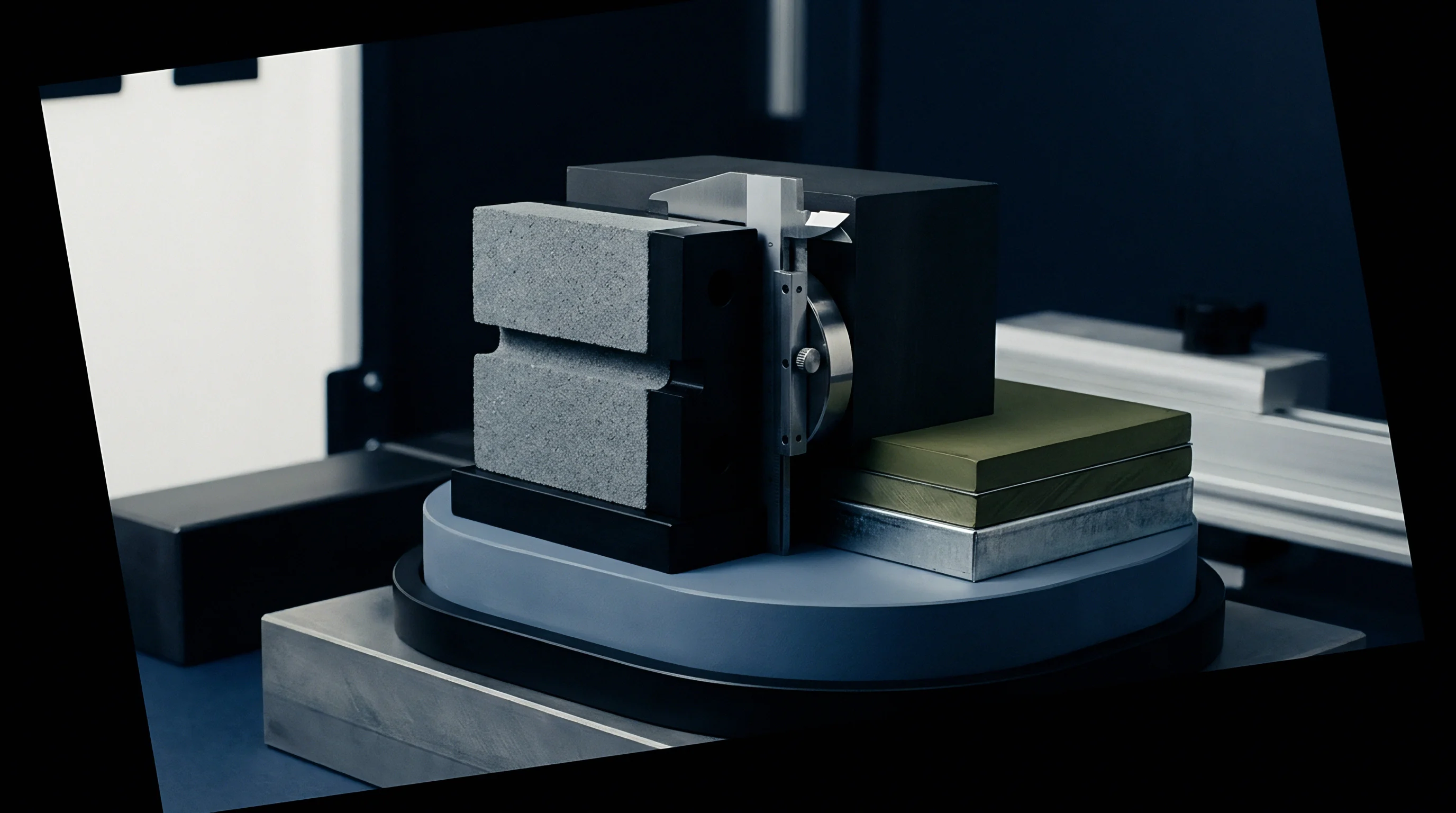
Structural bending in the outer test frame absorbs part of the cell force during heavy C-rate charging. When a pouch cell generates five kilonewtons of swelling force under full charge, a test channel frame with a mechanical stiffness of one hundred kilonewtons per millimeter deflects outward by fifty micrometers. If displacement transducers are mounted to the outer frame ends, reported cell thickness undercounts actual cell growth by fifty micrometers.
Closed-loop calibration algorithms compensate for this elastic frame stretch in real time.

Mathematical Frame Compliance Compensation Mechanics
Calculating true cell thickness involves subtracting structural frame deformation from the gross displacement reading. Consider a test setup applying an initial three hundred Newton preload to a sixty Ampere-hour NMC pouch cell held in a steel channel frame with verified structural stiffness of one hundred fifty Newtons per micrometer. During rapid charging, expansion force rises to five thousand three hundred Newtons, generating a force change of five thousand Newtons.
The gross displacement recorded by an outer LVDT reads one hundred forty micrometers. Frame deflection equals five thousand Newtons divided by one hundred fifty Newtons per micrometer, yielding thirty-three point three3 micrometers of structural frame displacement. True cell swelling equals one hundred forty micrometers plus thirty-three point three3 micrometers, totaling one hundred seventy-three point three3 micrometers.
Omitting structural stiffness calibration understates cell expansion by twenty-three point8 percent.
Internal friction masks the true mechanical expansion force exerted by the cell.
Factoring in thermal expansion across an environmental test sweep from twenty-five to forty-five degrees Celsius introduces further correction factors. A two hundred millimeter steel mounting column expanding under a twenty Kelvin temperature delta lengthens by forty-eight micrometers. Substituting an invar mounting column with a thermal expansion coefficient of one point two times ten to the minus sixth per Kelvin reduces column expansion to four point eight micrometers under the same temperature shift, eliminating forty-three point two micrometers of thermal measurement error.
Structural stiffness in swelling channels should exceed the maximum anticipated cell stiffness by at least one order of magnitude.
| Applied Load (Newtons) | Temperature Shift (Kelvin) | Frame Bending Deflection (micrometers) | Steel Arm Thermal Drift (micrometers) | Net Uncorrected Displacement Error (micrometers) |
|---|---|---|---|---|
| 1,000 | +5 | 6.67 | 12.0 | 18.67 |
| 3,000 | +10 | 20.00 | 24.0 | 44.00 |
| 5,000 | +20 | 33.33 | 48.0 | 81.33 |
| 8,000 | +35 | 53.33 | 84.0 | 137.33 |
| Data calculated for 200 mm steel sensor support column with frame stiffness of 150 N/micrometer. | ||||
Neglecting frame compliance calibration distorts swelling profile data, leading pack architects to over-design compression foams or miscalculate structural enclosure gaps, adding unnecessary mass and tooling expenses to volume pack builds.


Swell
Reversible lithium intercalation drives cyclic breathing, whereas irreversible solid electrolyte interphase growth causes permanent pouch growth. Chemistry determines swelling magnitude and force generation rate, compelling precise mechanical reference alignment tailored to specific format geometries.

Pouch and Prismatic Boundary Conditions
Flexible foil pouches rely on uniform surface clamping pressure to prevent localized gas pooling. Lacking outer rigid containment, pouch faces bulge outward centrally, producing localized delamination between current collectors and active material coatings. Prismatic cells incorporate thick aluminum housings that absorb internal pressure, yet end-wall bowing still occurs when internal gas accumulation or active material expansion exceeds three hundred kilopascals.
Silicon-graphite composite anodes exhibit volumetric changes exceeding three hundred percent at the particle level, translating to full-cell thickness increases over twenty percent across five hundred cycles. Precise swelling channel alignment prevents binding during these high-expansion regimes, keeping load cells operating within linear calibrated ranges.

Channel Zero Point Calibration Mechanics
Establishing an unvarying start position relies on ground ceramic reference blocks inserted between clamping plates.
- Clean reference platens and ceramic gauge blocks with isopropyl alcohol to remove oil particulates.
- Insert a certified ceramic gauge block matching the nominal dry thickness of the target cell between the channel platens.
- Apply the specified baseline mechanical preload force to the assembly using the primary force actuator.
- Zero all linear displacement transducers and strain gauge channels in the data acquisition software.
- Unload the channel, extract the ceramic gauge block, and check that displacement readings return to absolute zero within 0.5 micrometers.
- Position the target cell into the channel, re-apply the baseline preload, and begin the test log.
Silicon-composite anodes exhibit non-linear swelling acceleration past seven hundred charge cycles due to particle pulverization and continuous SEI re-formation.
Industry standards remain divided on whether reference alignment zero points should be established under ambient atmospheric conditions or inside thermal chambers at elevated pre-charge temperatures.


Claim
Cell procurement specifications demand strict definitions of swelling test methodology to prevent contractual disputes during lot qualification. Misaligned swelling test data leads directly to rejected production lots or contested warranty claims when cell performance fails to match laboratory claims.
Contractual Test Standards and Tolerances
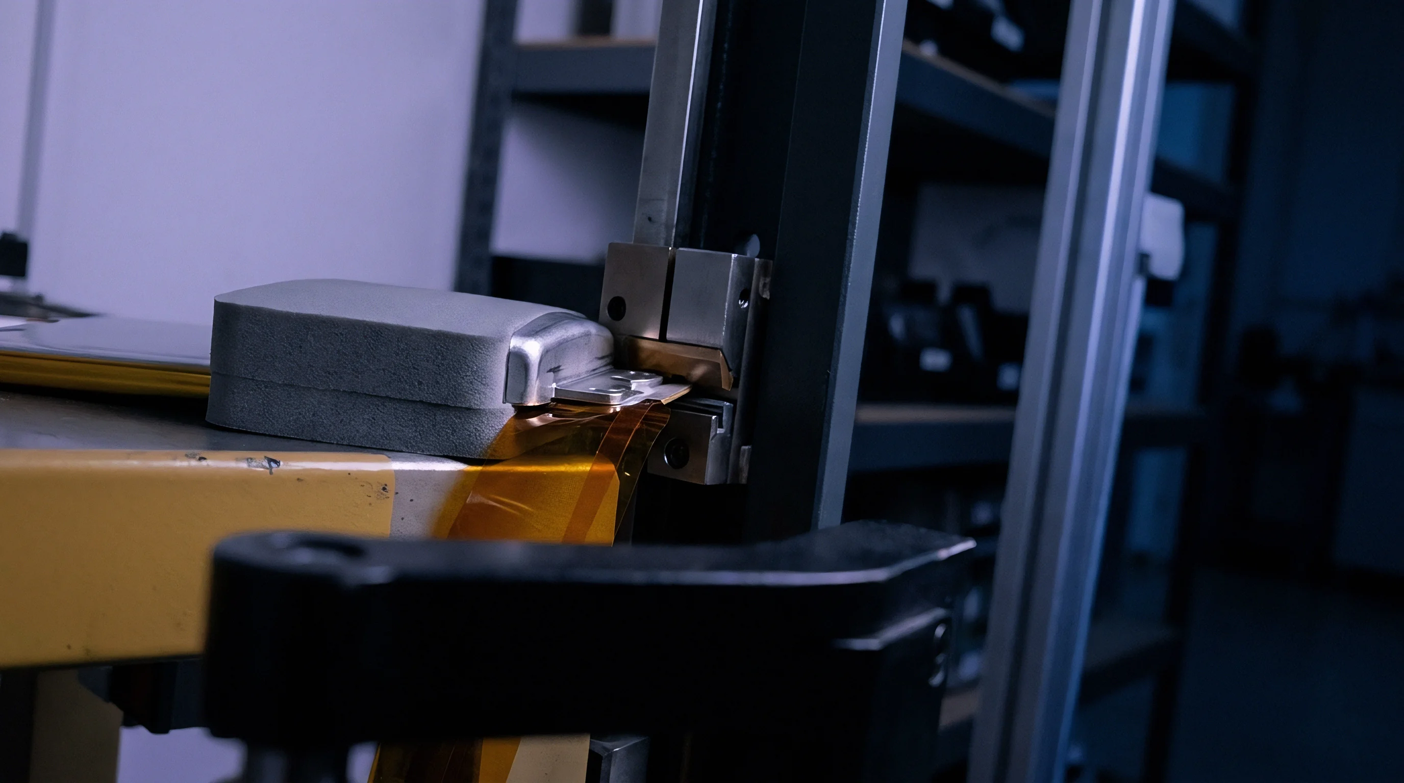
International procedures such as IEC 62660-3 dictate mechanical swelling limits during abuse and cycle testing. Technical annexes in cell supply agreements specify acceptable frame deflection limits, temperature compensation formulas, and transducer accuracy boundaries. Omitting physical channel reference alignment specs allows cell vendors to submit swelling curves measured on loose compliance rigs, hiding excessive cell face expansion under structural frame absorption.
Vendor Acceptance Checklists for Test Rig Deliveries
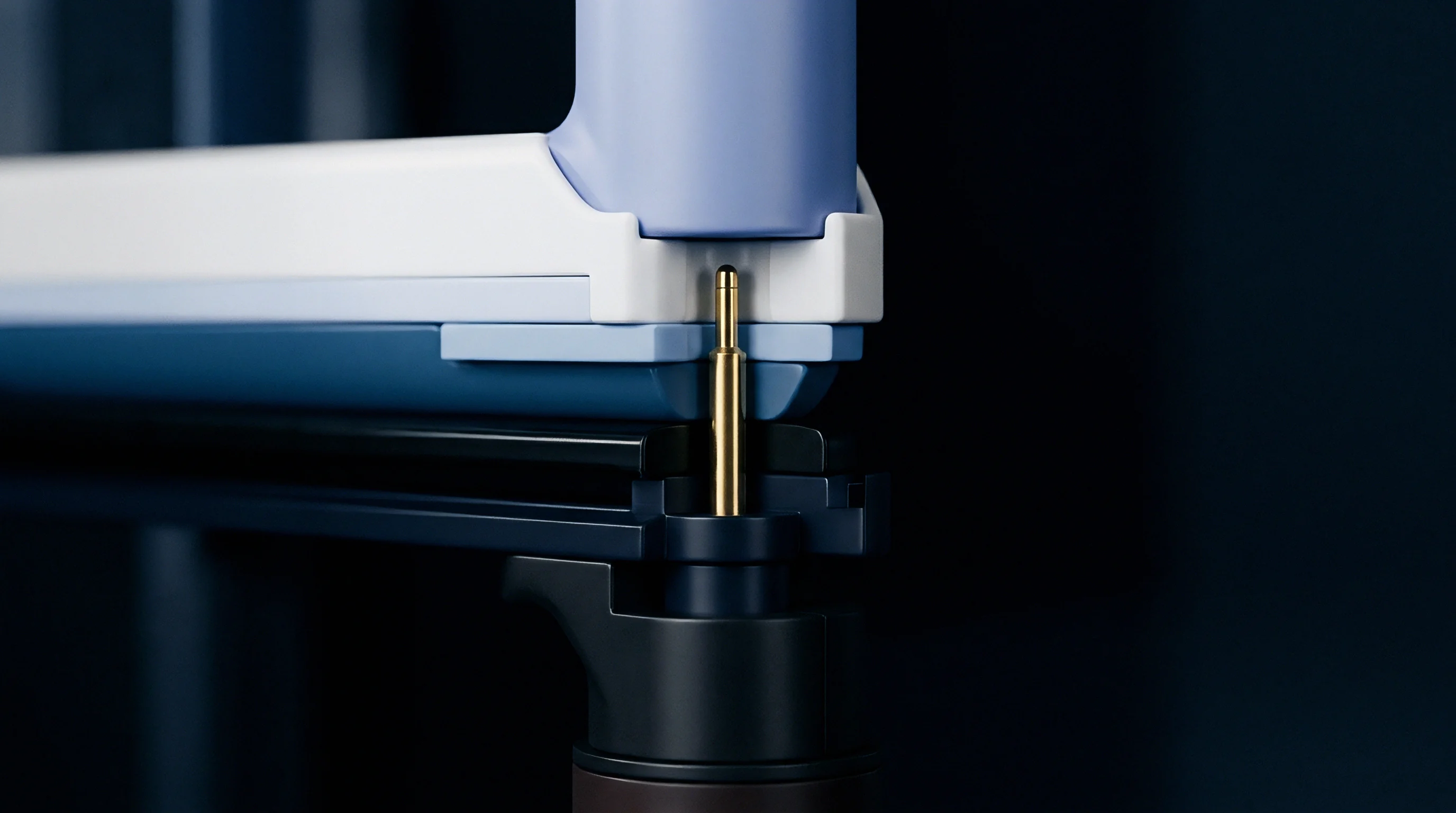
Receiving hardware from custom test equipment suppliers calls for rigorous qualification protocols. Testing incoming swelling channels against physical standards ensures compliance before commissioning.
Under IEC 62660-3 clause six point two, failure to document mechanical zero alignment invalidates vendor dimensional compliance submittals during lot acceptance disputes.
- Planar Parallelism Certification verifies that compression platens remain parallel within ten micrometers across full working stroke under maximum design load.
- Frame Stiffness Mapping documents deflection curves across applied force increments up to ten kilonewtons, yielding verified mechanical spring constants.
- Thermal Coefficient Audit confirms that sensor mounting arms maintain position stability within one micrometer across the complete environmental operating range.
- Transducer Linearity Check proves linear displacement readings maintain point-to-point error below zero point one percent of full scale.
A master supply agreement specifying swelling limits under ISO 12405-4 paragraph eight point three transfers all financial liability for cell casing deformation back to the cell manufacturer when test channel calibration logs verify zero reference drift within two micrometers over two thousand cycles.