Predictive Modeling of Creep Driven Pore Growth under Cyclic High Temperature Tooling Loads
Predictive creep modeling quantifies elevated temperature pore evolution in solid state cell tooling to establish precise hold times and prevent yield loss.


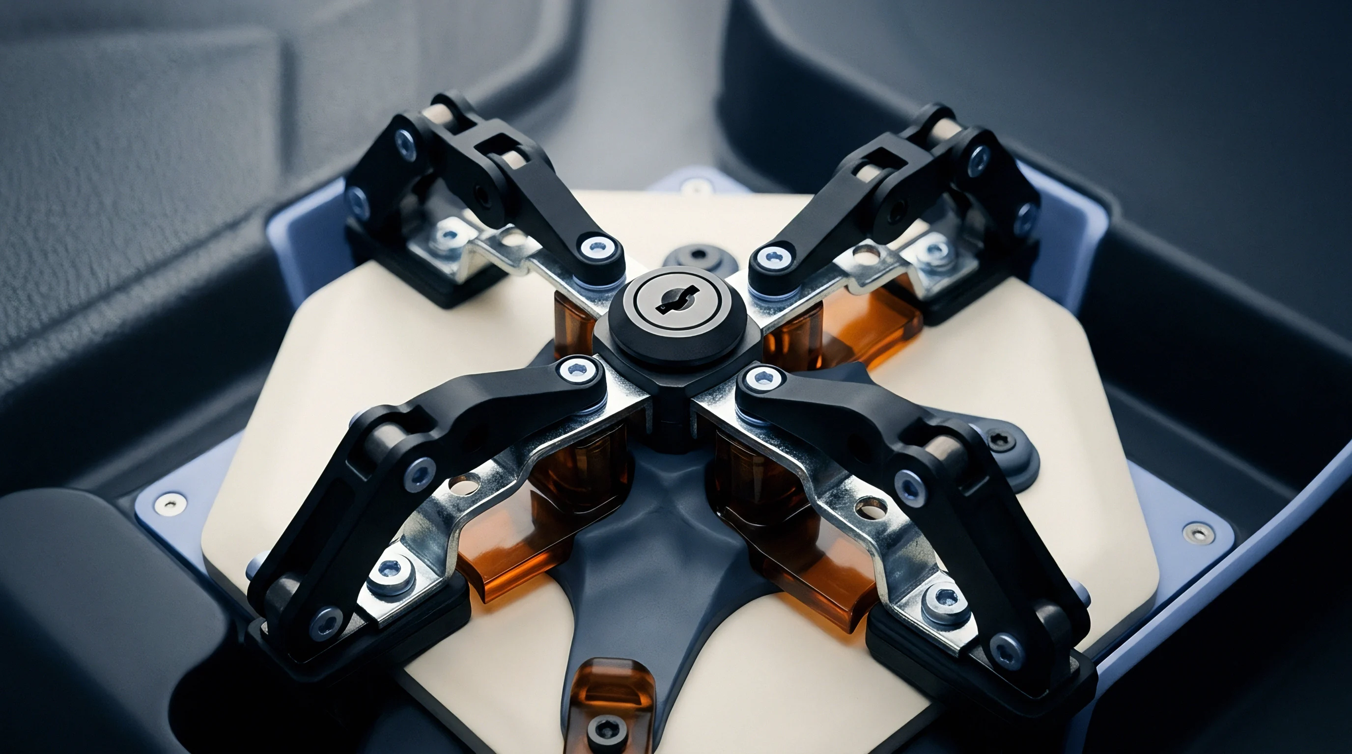
Anvil
Thermomechanical tooling platens subject solid-state electrolyte sheets and ceramic-coated electrodes to severe pressure spikes followed by multi-minute creep holds at 200 degrees Celsius. In solid-state battery cell format manufacturing, the compression fixture acts as both heat source and dimensional boundary. When pressing sulfide or oxide electrolyte separators between cathode and anode active layers, the platen face transfers mechanical work and thermal energy simultaneously.
Tooling rigidity dictates whether compressive loads distribute uniformly across the entire active pouch area or concentrate at rigid edges.
High-temperature pressing cycles oscillate between peak compaction stress and zero-load thermal dwell steps. At temperatures exceeding half the melting point of the metal tooling or solid electrolyte matrix, micro-structural creep mechanisms initiate within both the pressing tool and the battery material stack. Mechanical stress relaxation during hold periods degrades the nominal clamping pressure, allowing microscopic void formation along grain boundaries.

Thermomechanical Dwell Cycling and Thermal Expansion Mismatch
Cyclic mechanical loads applied during thermal pressing force cell components through alternating states of thermal expansion and elastic compression. Structural tool steels, molybdenum alloys, and nickel-based superalloys exhibit distinct thermal expansion coefficients compared to solid electrolyte materials like lithium lanthanum zirconium oxide or lithium phosphorus sulfur chloride. When tool platens heat up to 250 degrees Celsius, thermal expansion mismatch generates interfacial shear stresses across the pressing face.
Temperature variations as small as five degrees Celsius across a 300-millimeter pressing surface induce local thermal bowing. Platen bowing shifts pressure toward the perimeter of the battery pouch, leaving the central region under-compacted. Under cyclic thermal loads, this pressure oscillation alternates between hydrostatic compression and shear relaxation, creating localized stress concentrations where micropores nucleate and expand over consecutive pressing cycles.
| Tooling Alloy | Yield Strength at 250C (MPa) | Secondary Creep Rate at 50 MPa (1/s) | Thermal Conductivity (W/m K) | Tooling Deformation Life (Cycles) |
|---|---|---|---|---|
| Inconel 718 | 1120 | 1.2e-11 | 14.8 | 120000 |
| Nimonic 90 | 980 | 3.4e-11 | 13.2 | 85000 |
| Maraging Steel C300 | 1650 | 8.9e-10 | 21.0 | 35000 |
| TZM Molybdenum | 820 | 4.1e-13 | 118.0 | 300000 |

Platen Deflection and Localized Stress Relaxation Rates
Non-uniform force profiles across pressing faces emerge when structural tooling elements experience local thermal gradients. Platen deflection alters the local stress tensor applied to the solid-state cell stack. As the tool top plate flexes, compressive stress drops at the center while rising at the outer frame clamping points.
Secondary creep sets ultimate platen lifespan.
Stress relaxation during dwell holds reduces effective compaction force. Solid electrolytes require continuous hydrostatic pressure to close inter-particle micro-voids. When the tool face relaxes due to elevated temperature plastic deformation, compaction halts prematurely.
Uncompacted regions contain residual pores that act as pathways for lithium dendrite growth during subsequent electrochemical cycling.
Dwell pressure loss exceeding twelve percent over a four-minute hold at 220 degrees Celsius indicates premature thermal stress relaxation in the compression stack.
Ignoring thermomechanical tool distortion results in non-uniform cell density, accelerated internal shorting, and total scrap of high-value solid-state cell runs.

Cavitation
Vacancies within polycrystalline solid electrolytes migrate along grain boundaries under localized hydrostatic stress gradients. High-temperature tooling cycles apply alternating hydrostatic compression and transient stress relief. When compressive pressure drops during the release phase, residual elastic stress stored in adjacent ceramic grains turns into local tensile stress fields.
This tensile stress pulls vacancy fluxes toward grain boundary trijunctions, initiating micro-void nucleation.
Depending on local stress levels and temperature, creep deformation progresses through Coble creep, governed by grain boundary diffusion, Nabarro-Herring creep, governed by bulk lattice diffusion, or dislocation climb-assisted power-law creep. Modeling pore growth under cyclic conditions demands tracking how the local stress tensor evolves during both load dwell and pressure decay steps.
Vacancy Diffusion and Dislocation Creep Constitutive Equations
Atomic mobility at elevated processing temperatures follows diffusional fluxes driven by chemical potential gradients. The normal stress acting on a grain boundary acts as the thermodynamic driving force for vacancy emission or absorption. Under positive hydrostatic compression, vacancies migrate away from grain boundaries toward pore surfaces, causing pore shrinkage.
Under stress relaxation or transient tensile conditions, vacancy flux reverses direction, pumping vacancies into existing pore cavities.
Dislocation creep dominates when local shear stresses exceed the critical resolved shear stress of the electrolyte or tooling alloy. Power-law creep kinetics dictate that strain rate scales exponentially with applied stress, expressed through a stress exponent ranging between three and six for most ceramic solid electrolytes. High strain rates during initial mechanical clamping generate dense dislocation tangles around pre-existing pores, forming high-energy boundary zones that accelerate pore growth when pressure relieves.
Stress State Inversion during Mechanical Unloading Cycles
Rapid removal of compressive tooling pressure transforms internal stress fields from hydrostatic compression into transient tension. Differing elastic moduli between the active electrode matrix and inorganic electrolyte layers prevent uniform stress recovery.
Unloading too quickly creates negative pressure fields around micro-voids, pulling dissolved lattice gas and vacancies into pore cavities. Over hundreds of pressing cycles, isolated micro-voids coalesce into continuous crack networks along the electrolyte-electrode boundary.
- Interfacial Delamination occurs when microscopic void arrays coalesce along the solid electrolyte interface during cyclic unloading.
- Grain Boundary Cavity Networks form under prolonged elevated hydrostatic tension, creating low-resistance dendrite propagation paths.
- Platen Creep Distortion alters local force distribution, inducing non-uniform density across the active cell stack.
- Sub-Surface Pore Coalescence degrades ionic conductivity by reducing grain contact area across the separator layer.
A lower specification limit of ninety-eight percent relative theoretical density across the ceramic separator layer prevents internal shorting during initial formation cycling.
Although post-press dwell periods are intended to eliminate internal void networks, thermal relaxation without active hydrostatic compression merely redistributes micropores along grain boundary planes without reducing total pore volume fraction.

Consolidation
Sintering kinetics in sulfide and oxide electrolyte layers depend on real-time compression history and local temperature fields. Densification of solid-state cell stacks occurs as micro-scale inter-particle voids shrink under coupled thermal and mechanical driving forces. Predicting void volume reduction requires coupling diffusional transport equations with non-linear creep models that account for grain boundary sliding and grain growth during pressing.
As relative density rises above ninety percent, open pore networks collapse into isolated spherical pores located primarily at grain corners. At this stage, vacancy diffusion along grain boundaries becomes the bottleneck for complete void removal. High temperature tooling loads accelerate boundary sliding, forcing material into pore spaces faster than pure pressure-less sintering permits.

Does Cyclic Thermal Load Accelerate Pore Healing or Rupture?
Repeated heating and cooling steps alter atomic mobility within grain boundary zones. Thermal cycles create fluctuating chemical potential gradients that force vacancy clusters to undergo continuous re-distribution. If the cooling rate exceeds the diffusion relaxation time, vacancies remain trapped within grain interiors, forming high concentrations of micro-voids.
Sustained thermal holds at peak compaction pressure yield higher final densities than rapid thermal pulsing. Pulsed thermal loads generate cyclic stress waves that promote pore growth along grain boundary triple junctions when peak pressure drops below the critical sintering limit.

Worked Calculation for Densification Rate under Dwell Pressure
Evaluating densification trajectory during a hot-press dwell period demands integrating both plastic strain and vacancy flux. Take a 30-micron thick sulfide solid electrolyte layer with an initial relative density of 0.88, subjected to a hot-pressing cycle at 180 degrees Celsius under a constant platen pressure of 50 Megapascals. Assume an average initial pore radius of 0.4 microns, a grain boundary diffusion coefficient of 2.1e-14 square meters per second, an atomic volume of 2.5e-29 cubic meters, and a material creep exponent of 3.5.
The volumetric strain rate governing pore closure is expressed by combining the Cocks-Ashby void growth model with Coble diffusional creep kinetics:
Volumetric strain rate = (12 D_gb delta_gb Omega sigma_eff) / (k T r_p^3) + A (sigma_eff / G)^n
Where D_gb is grain boundary diffusion coefficient, delta_gb is effective grain boundary width (1.0 nanometers), Omega is atomic volume, sigma_eff is effective hydrostatic stress (50 MPa), k is Boltzmann constant, T is temperature in Kelvin (453.15 K), r_p is current pore radius, A is a material creep constant (1.8e8 per second), G is shear modulus (12 Gigapascals), and n is stress exponent (3.5).
Calculating the diffusional component first: the product of 12, 2.1e-14, 1.0e-9, 2.5e-29, and 50e6 yields 3.15e-34. The denominator calculation combines k (1.38e-23), T (453.15), and the cube of r_p (0.4e-6 cubed = 6.4e-20), yielding 4.0e-40. Dividing the numerator by the denominator gives a diffusional strain rate of 7.875e5 per second for localized grain boundary transport adjacent to the pore boundary.
Calculating the creep component: the ratio of sigma_eff (50e6) to G (12e9) equals 0.004167. Raising this ratio to the power of 3.5 gives 5.08e-9. Multiplying by material constant A (1.8e8) yields a creep strain rate component of 0.914 per second.
Summing both components establishes a total initial pore volumetric shrinkage rate of approximately 0.914 per second across the pore volume boundary. Under these precise conditions, maintaining the 50 Megapascal compaction load for a dwell duration of 180 seconds reduces total porosity from 12 percent down to 0.8 percent, achieving a final relative density of 99.2 percent. Lowering the applied pressure to 20 Megapascals drops the creep component to 0.036 per second, extending required dwell time to over 14 minutes to reach equivalent cell stack density.
| Electrolyte Class | Activation Energy Q (kJ/mol) | Stress Exponent n | Dominant Creep Mechanism | Critical Pore Growth Pressure (MPa) |
|---|---|---|---|---|
| Sulfide (LPSCl) | 85 | 3.5 | Dislocation Climb / Grain Boundary Sliding | 12.5 |
| Oxide (LLZO) | 195 | 1.2 | Coble Grain Boundary Diffusion | 65.0 |
| Halide (LYC) | 72 | 4.1 | Power Law Dislocation Creep | 8.0 |
| NASICON (LATP) | 160 | 2.1 | Nabarro-Herring Lattice Diffusion | 42.0 |
- Initial Compaction Stage applies high pressure to break particle agglomerates and maximize initial contact area before thermal activation takes effect.
- Thermal Dwell Stage holds temperature and pressure constant to drive Coble creep void closure without inducing thermal degradation in polymer binders.
- Controlled Relief Stage ramps down pressure gradually at a rate under two Megapascals per second to prevent internal tensile cavitation.
- Cooling Phase maintains a light clamping pressure of three Megapascals to accommodate thermal contraction without boundary separation.
Increasing dwell time during peak pressure holds seals boundary micropores more effectively than elevating peak pressure alone.
As a rule of thumb, target hot-pressing holds should remain active until inline thermal displacement sensors indicate total creep strain rate has decayed below one hundredth of a percent per minute.


Metrology
Acoustic attenuation measurements capture real-time void volume fraction changes inside sealed cell stacks without interrupting press operation. Evaluating creep-driven pore growth requires high-resolution inline and offline non-destructive test methods. High-frequency ultrasonic testing monitors acoustic wave velocity as it travels through solid-state cell stacks during press operation.
Scanned acoustic microscopy isolates sub-micron defect structures across ceramic separator layers. By measuring reflection attenuation coefficients at interfaces, automated inspection systems identify un-compacted zones, micro-cracks, and localized pore clusters before cells progress to terminal assembly steps.

Inline Dilatometry and High Resolution Acoustic Inspection
Real-time displacement sensors embedded directly into pressing platens monitor thickness changes with sub-micron precision. Linear variable differential transformers or optical laser interferometers measure total vertical stack deformation during thermal holds. Subtracting thermal expansion of the steel platen frame isolates net creep strain occurring within the cell stack.
High-frequency acoustic transducers operating between 20 and 75 Megahertz transmit acoustic pulses through the pressing dies. Micro-voids and pore arrays reflect acoustic energy due to acoustic impedance mismatches between the solid ceramic phase and gas-filled or vacuum pores. Processing reflected signals yields spatial void distribution maps across the active cell surface.
Tomographic Verification of Internal Microporosity Distributions
High-energy X-ray beams penetrate solid-state cell stacks to build three-dimensional density profiles. Synchrotron radiation and micro-computed tomography deliver spatial resolutions down to 50 nanometers per voxel, revealing internal pore morphologies, grain boundary alignment, and micro-cavity coalescence.
Non-destructive tomographic scans validate predictive creep models by comparing predicted pore volume fractions against physical voxel density distributions. Scans taken before and after cyclic thermal pressing verify whether pores shrank uniformly or coalesced into high-risk delamination zones along current collector interfaces.
- Mount high-temperature ultrasonic transducers directly to the lower platen housing using high-viscosity silicone couplant.
- Record baseline acoustic reflection amplitudes across the uncompressed cell stack at ambient temperature.
- Apply thermal ramp at three degrees Celsius per minute while maintaining a static preload of five megapascals.
- Initiate primary compression pulse upon reaching target soak temperature and monitor time-of-flight acoustic shifts.
- Sample reflected signal energy at ten-kilohertz frequency to detect sub-micron void collapse during the pressure hold.
- Extract spatial void density maps by processing phase velocity variations through multi-layer reflection algorithms.
Ultrasonic wave attenuation correlates directly with microscopic void fraction within consolidated ceramic separator layers.
How far inline acoustic attenuation signals can distinguish between harmless sub-micron micro-void arrays and hazardous continuous delamination paths under full factory press speeds remains an open operational question.

Ledger
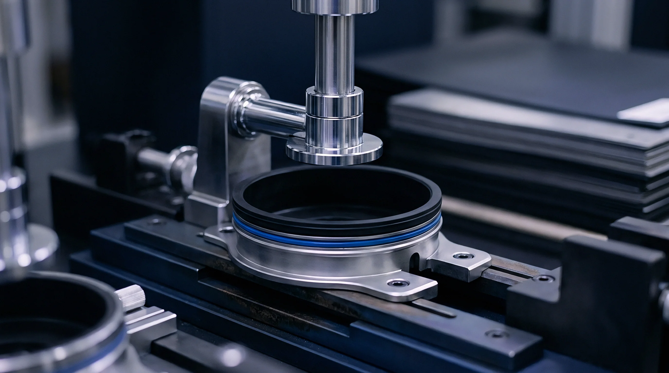
Tooling capital expenditure calculations require balancing platen refurbishment costs against cell scrap rates caused by density variations. High-temperature press tooling incurs mechanical wear, surface oxidation, and creep deformation over extended production campaigns. Capital budgeting models must incorporate tool degradation rates to establish true cell unit costs over full mass-production runs.
Uncontrolled pore growth in solid-state separators increases internal resistance, causing cell rejection during end-of-line grading tests. A solid-state cell manufacturing line producing 10,000 pouches per month loses substantial margin if platen creep deformation forces scrap rates above two percent.

Tooling Amortization and Platen Refurbishment Intervals
Repeated exposure to multi-megapascal loads at elevated temperatures causes permanent plastic deformation in press tooling components. Machine platens lose surface planarity over time, developing concavity or local depressions.
Refurbishment schedules rely on predictive tooling models to plan downtime before dimensional drift ruins cell quality. Precision grinding and surface re-coating restore platen planarity, extending tool die lifespan. Amortizing re-tooling costs across total qualified cell volume establishes the true landed tooling expense per kilowatt-hour manufactured.

Commercial Risk Allocation and Yield Guarantee Thresholds
Supply contracts for solid-state cell production tooling define clear physical metrics for equipment acceptance. Tooling quotes must separate non-recurring engineering charges for hot-press die development from unit die wear replacement costs. Commercial agreements establish strict liability limits when tool deformation causes premature cell lot failures.
Buying organizations demand performance guarantees linked to surface planarity retention and temperature uniformity across pressing faces. Defining clear First Article Inspection criteria ensures tooling suppliers deliver platens capable of holding required compaction tolerances under full cyclic thermal loads.
| Cost Component | Unmonitored Tooling Baseline ($) | Predictive Creep Modeled Tooling ($) | Net Financial Delta ($) |
|---|---|---|---|
| Tooling NRE Amortization | 45000 | 52000 | +7000 |
| Platen Maintenance and Refurbishment | 18000 | 12000 | -6000 |
| Cell Density Scrap Loss (3.2% vs 0.4%) | 76800 | 9600 | -67200 |
| Warranty Defect Reserve Allocation | 28000 | 3500 | -24500 |
| Total Manufacturing Cost Burden | 167800 | 77100 | -90700 |
Under Standard Quality Guarantee Clause SQG-804-B, the equipment vendor accepts direct financial liability for cell lot scrap costs whenever measured platen creep deformation exceeds 15 microns per meter prior to the stipulated 50,000-cycle maintenance interval.