Long Term Creep Stress Relaxation and Anode Lithium Plating in Oversized Prismatic Cells
Maintaining active spring load above zero point three megapascals prevents localized pressure drop and anode lithium plating in oversized prismatic cells over extended service life.

Wedge
Mechanical stack pressure applied to large-format prismatic cells undergoes decay over thousands of charge-discharge cycles. In oversized prismatic cells with capacities exceeding two hundred ampere-hours, internal compression maintains uniform physical contact between electrode layers and suppresses anode thickness expansion during lithiation. Operating environments impose sustained mechanical loads and cyclic thermal stress on compression components, causing permanent elastic loss in buffering media.

Compressive Stress Decay in Large Format Prismatic Stacks
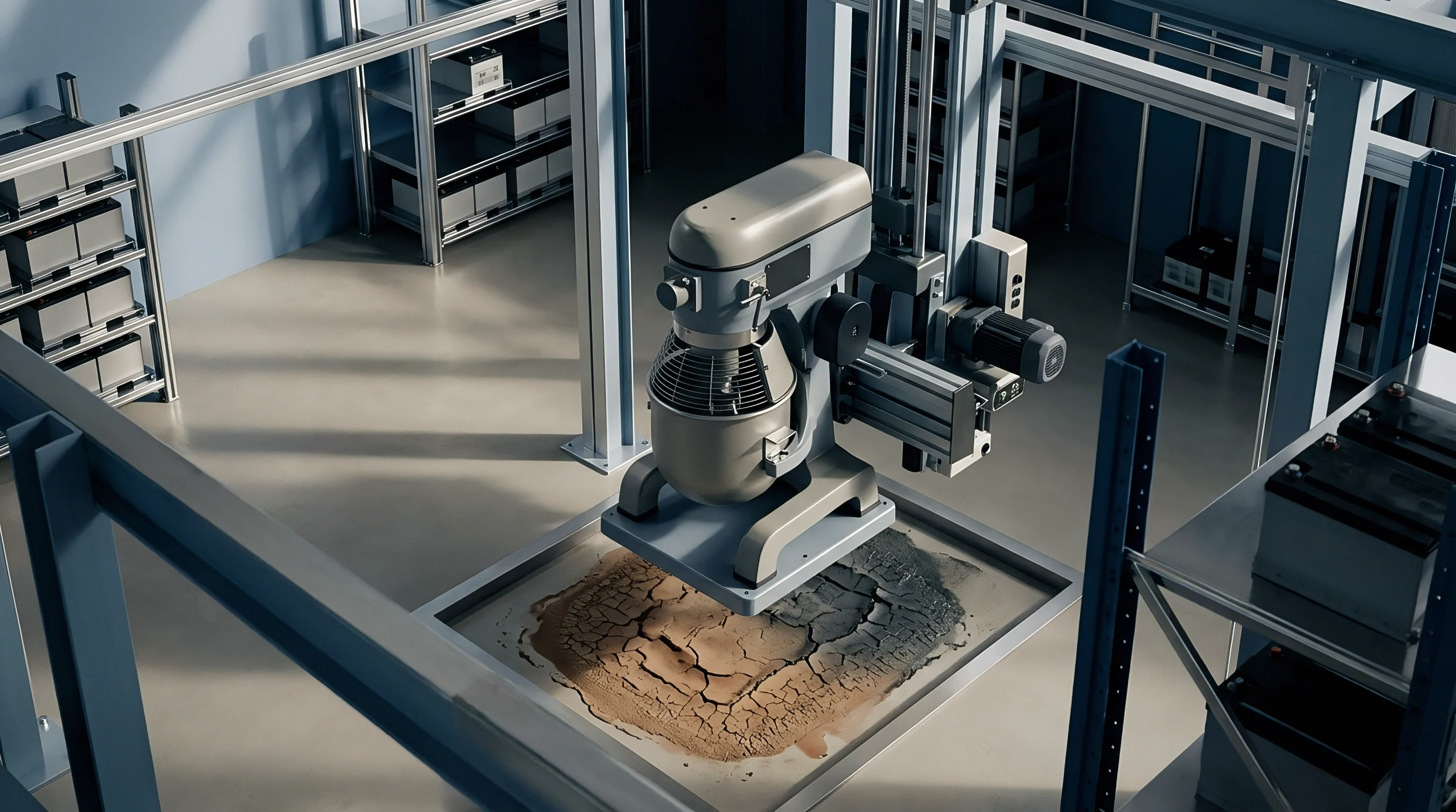
Long term mechanical loads applied across cell faces induce continuous deformation in elastomeric buffer media. Microcellular polyurethane pads and silicone foams, installed between adjacent prismatic cells to absorb cyclic swelling, exhibit visco-elastic relaxation over extended operation. Initial mechanical stack pressure set between zero point three and zero point eight megapascals steadily declines as the elastomeric matrix undergoes molecular chain reorientation under strain, reducing the restoring force exerted against the cell casing.
When stack compression drops below nominal design thresholds, internal restraint on the electrode roll decreases. Localized interfacial pressure variation develops across the active electrode area, creating regions where contact between the separator and the graphite anode coating relaxes. In rigid frame pack assemblies without dynamic tension compensation, structural relaxation leads to permanent mechanical unloading.
| Buffering Material Type | Initial Stack Load (MPa) | Load Retention at 1000h (45°C) | Creep Rate (% per decade) | Permanent Set (%) |
|---|---|---|---|---|
| Microcellular Polyurethane Foam | 0.50 | 68% | 8.2 | 14.5 |
| Silicone Sponge Rubber | 0.50 | 82% | 4.1 | 6.2 |
| Cross-linked Polyethylene Foam | 0.50 | 51% | 12.8 | 22.1 |
| EPDM Closed-Cell Sponge | 0.50 | 61% | 9.4 | 18.0 |
Microcellular polyurethane compression pads retain sixty-two percent of initial clamping pressure after five thousand thermal cycles at forty-five degrees Celsius.

Separator Polymeric Creep under Sustained Thermal Cycling
Polyolefin microporous membranes experience dimensional loss under mechanical preloads at elevated temperatures. Wet-process polyethylene and polypropylene separators carry microscopic pore architectures that deform under continuous pressure. Sustained stack loads force the polymer fibrils to collapse into adjacent void spaces, decreasing membrane porosity and increasing ionic tortuosity.
Thinner ceramic-coated separators preserve structural puncture resistance, but sustained creep strain alters electrolyte retention within the separator matrix. Reduced electrolyte volume inside compressed pores increases bulk ionic resistance across the separator layer. The physical cascade leading to localized mechanical unloading follows a predictable progression.
- Initial Viscoelastic Settling Elastomer buffering pads undergo rapid stress relaxation within two hundred hours of pack assembly and compression torque application.
- Separator Wall Thinning Sustained mechanical force at elevated operating temperatures compresses the microporous polymer matrix, reducing nominal membrane thickness.
- Localized Stack Unclamping Non-uniform swelling across the electrode face causes localized stress relaxation, creating zones where mechanical contact force drops below one hundred kilopascals.
- Interfacial Gap Formation Loss of local compression creates microscopic separations between the ceramic coated separator and the graphite anode coating.
Oversized prismatic modules operated without active mechanical compensation suffer localized delamination, non-uniform current distribution, and accelerated capacity roll-off.


Kinetics
Electrochemical reaction pathways at the graphite anode face depend heavily on uniform mechanical contact across the active electrode surface. Localized reductions in stack pressure alter salt concentration gradients within the liquid electrolyte contained in the separator pores. When compressive forces fall below minimum operational limits, interfacial distance between the separator and anode increase micro-spatially, elevating local liquid-phase charge transfer resistance.
Anode Interfacial Overpotential and Localized Potential Drops
Charge transfer resistance across the electrode interface varies inversely with applied mechanical constraint. Lower stack pressure increases the local electrolyte film thickness, extending lithium ion transport pathways during high-rate charging, where plating typically begins along edges. Higher localized internal resistance increases local ohmic drop, forcing the equilibrium potential of the graphite anode down toward negative values relative to metallic lithium.
Local overpotential shifts govern reaction selectivity during fast charging or cold weather charging. When mechanical relaxation creates low-pressure zones across large prismatic cell plates, current redistributes toward regions of lower contact resistance. Local current density spikes along boundary lines adjacent to relaxed stack zones.
Under high localized current densities, the potential of the intercalating graphite surface drops below zero volts versus the lithium reference electrode, precipitating metallic lithium deposition onto the anode face.
Anode potential drops below zero volts versus lithium reference whenever local charge transfer resistance exceeds the threshold established by bulk intercalation kinetics.

Pressure Dependent Lithium Intercalation Margins
Local current density distribution becomes highly non-uniform when local stack load fluctuates across the cell face. Unconstrained anode zones expand during lithiation, consuming available pore space and compressing adjacent separator areas. Non-uniform mechanical constraints create uneven solid electrolyte interphase film growth, further exacerbating localized resistance variations.
Lithium ions deposit as metallic dendrites or mossy structures instead of intercalating cleanly into the graphite lattice structure. Metallic deposits react with organic solvents in the electrolyte, forming secondary solid electrolyte interphase layers that consume active lithium inventory permanently as dendrites breach ceramic separators. Loss of active lithium reduces cell discharge capacity while increasing gas generation inside the sealed aluminum casing.
Whether low-temperature regeneration pulses can re-intercalate metallic lithium deposits formed under relaxed stack pressure remains an active subject of battery degradation research.


Bench
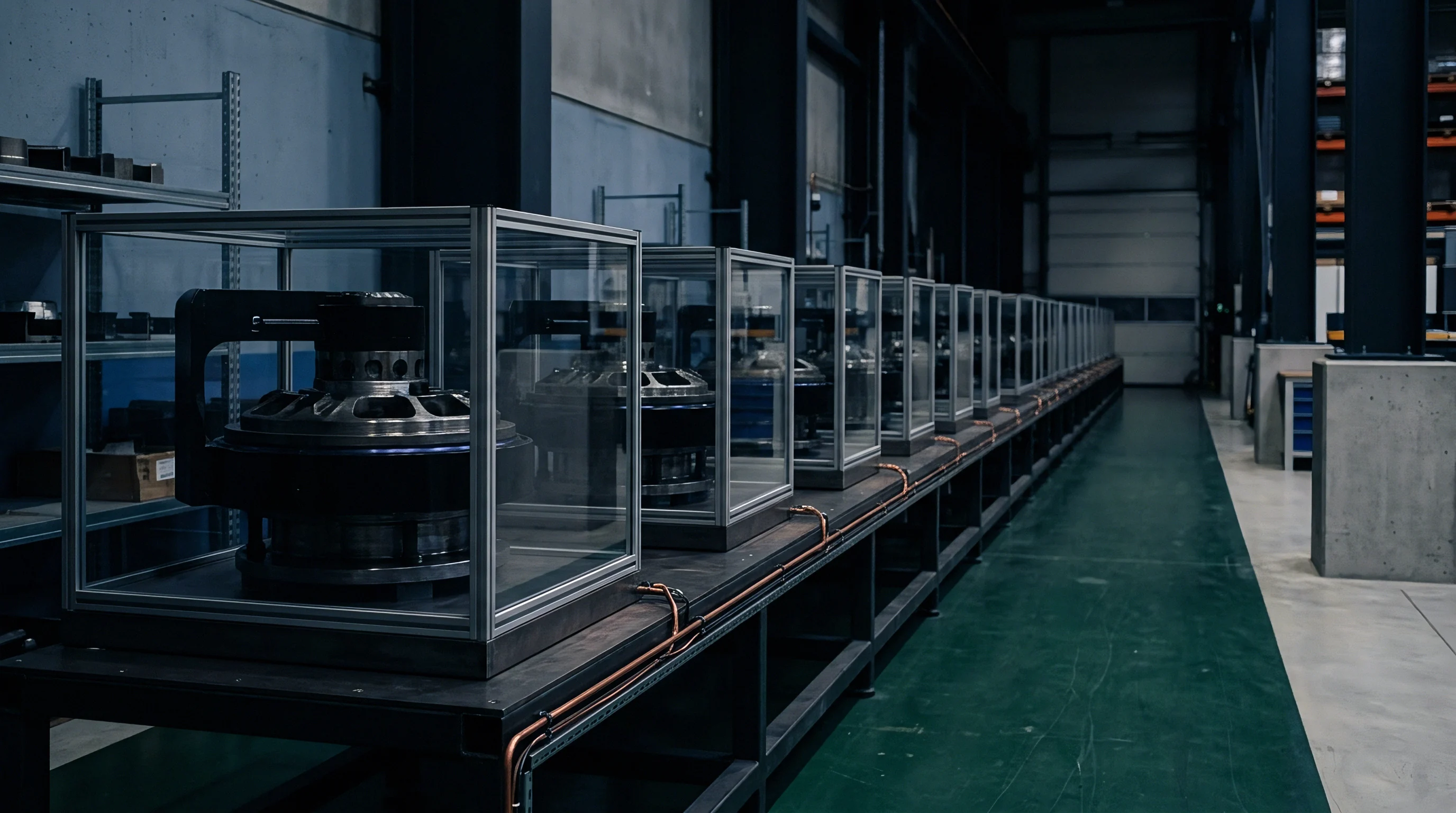
Laboratory qualification protocols isolate mechanical force relaxation from thermal aging through operando strain and impedance diagnostics. Specialized test fixtures equipped with load cells and displacement sensors track real-time changes in cell swelling force and stack pressure decay over extended cycle profiles. Integrating mechanical load control into electrical cycling channels provides direct measurement of pressure dependent degradation mechanisms.

Where Does Operational Pressure Relaxation Trigger Plating?
In situ stack pressure monitoring combined with operando dilatometry identifies exact mechanical thresholds where metallic deposition begins. Incremental capacity analysis and differential voltage spectroscopy detect subtle electrochemical signatures corresponding to early stage lithium plating. As cells swell during charge, shifts in the position and height of differential capacity peaks indicate lithium inventory loss caused by active lithium isolation in plated layers.
Electrochemical impedance spectroscopy under controlled mechanical loads reveals distinct changes in charge transfer semicircles as stack pressure decreases, accompanied by rightward shifts in Warburg tails. High-frequency intercept values track bulk electrolyte resistance, while mid-frequency semicircles reflect charge transfer kinetics at the electrode interfaces. Monitoring these parameters during prolonged cycling highlights structural relaxation points where internal impedance begins an irreversible upward trend.
Quantifying the impact of mechanical clamping systems requires evaluating dynamic spring preloads against rigid structural constraints. A representative engineering test protocol demonstrates the operational performance difference between static and active compression designs over extended cycling.
Take a three hundred and four ampere-hour lithium iron phosphate prismatic cell module in a sixteen-cell series configuration. Assume an initial applied compression stack load of zero point five megapascals across a two thousand four hundred square centimeter cell face, equal to twelve kilonewtons total clamping force. Testing evaluates two mechanical constraint frameworks operating under continuous one C fast charging at fifteen degrees Celsius over three thousand cycles.
Under a static tie-rod rigid frame assembly, viscoelastic creep in the internal separators and elastomeric spacer pads reduces stack pressure to zero point twelve megapascals after three thousand cycles. Mid-frequency charge transfer resistance increases by thirty-eight percent due to localized interfacial gap formation. Differential capacity analysis indicates an onset of localized anode lithium plating at cycle eighteen hundred, accelerating capacity loss and reducing state of health to seventy-six percent at cycle three thousand.
Under an active coil-spring compression frame designed to maintain a minimum dynamic load of zero point three five megapascals, stack pressure decay stabilizes at zero point three six megapascals over three thousand cycles. Mid-frequency charge transfer resistance growth remains constrained to eleven percent. Plating signatures remain absent from differential capacity curves, allowing the module to retain eighty-seven percent state of health at cycle three thousand while extending projected service life to six thousand two hundred cycles.
- Clean and mount the three hundred and four ampere-hour cell inside a temperature-controlled environmental chamber maintained at twenty-five degrees Celsius.
- Install dual flat load cells between the cell face and side compression plates, torquing securing bolts to apply zero point five megapascals uniform pressure.
- Connect multi-channel electrochemical impedance spectroscopy leads to measure baseline high-frequency resistance and charge-transfer semicircles from ten kilohertz to ten millihertz.
- Execute fifty baseline discharge cycles at zero point five C rate to stabilize solid electrolyte interphase film structure before initiating creep acceleration.
- Subject the assembly to dynamic mechanical stress relaxation profiles while logging face pressure decay, operational voltage curves, and differential capacity signatures.
Active spring compensation extends prismatic cell cycle life by preserving electrode contact pressure above the threshold where local overpotentials trigger metallic deposition.
Module frame deflection, spring fatigue, and structural elastic loss fall outside standard cell warranty terms.


Transit
Regulatory approval for moving high-capacity battery modules depends on proving structural stability and resistance to internal short circuits after field aging. Mechanical degradation inside oversized prismatic cells reduces their tolerance to transport shock and vibration profiles. UN 38.3 testing standards mandate rigorous physical evaluation to certify that cells remain safe during commercial movement across international borders.

Transport Testing Integrity after Long Term Stack Relaxation
Vibration and shock qualification trials verify whether aged modules retain structural integrity under mechanical excitation. UN 38.3 Test 3 specifies sinusoidal vibration sweeping between seven and two hundred hertz, while Test 4 applies half-sine shock impacts reaching one hundred and fifty g peak acceleration. Aged cells experiencing internal stack relaxation suffer internal jellyroll movement under these physical acceleration profiles.
When internal stack pressure drops, friction holding electrode layers rigid decreases. Internal components shift relative to the outer aluminum casing during transportation shaking. Friction between relaxed separator membranes and active electrode coatings induces mechanical erosion, increasing the risk of micro-shorts or localized separator tearing during international transit.
| Standard Reference | Mandated Test Parameter | Mechanical Variable Evaluated | Regulatory Failure Criteria |
|---|---|---|---|
| UN 38.3 T.3 | Vibration 7Hz to 200Hz for 3 hours | Internal electrode stack movement | Mass loss, leakage, rupture, open circuit voltage drop below 90% |
| UN 38.3 T.4 | Half-sine shock 150g peak, 6ms duration | Structural anchor and tab weld integrity | Fire, explosion, internal short circuit, enclosure breach |
| IEC 62133-2 Cl. 7.3.2 | Forced internal short circuit test | Separator puncture resistance under load | Thermal runaway, shell flame rupture, hazardous gas expulsion |
| EU Reg 2023/1542 | Annex VII State of Health parameter audit | Capacity fade and resistance accumulation | Non-compliance with battery passport data accuracy rules |
Failure to demonstrate structural stack pressure retention under UN 38.3 Test 3 invalidates the cell test summary and halts commercial dangerous goods shipments at regional freight hubs.

European Regulatory Filings for Electrochemical Safety Retention
Mandatory product passport documentation obligates battery suppliers to disclose state of health metrics and safety parameters. European Union Battery Regulation 2023/1542 Annex VII requires tracking internal resistance evolution and capacity degradation throughout the battery lifecycle. Prismatic cells exhibiting accelerated aging caused by stack relaxation fail compliance audits if logged safety parameters deviate from initial type-approval filings.
Maintaining compliance across distribution networks requires strict documentation and physical verification before releasing aged energy storage inventory for transport.
- Verification of Stack Preload Mechanical inspectors verify module endplate tension and bolt torque values against factory baseline specifications before issuing dangerous goods clearance certificates.
- Audit of Test Summaries Shipping documentation contains accredited laboratory test summaries confirming compliance with UN 38.3 clause 38.3.5 requirements after simulated creep aging.
- Isolation of Dendrite Risk Electrochemical impedance checks confirm charge transfer resistance remains within safety margins to exclude internal metallic lithium growth prior to air freight.
- Carrier File Assembly Mandatory dangerous goods documentation accompanies every shipment, carrying shippers declarations, safety data sheets, and accredited laboratory certification records.
Under UN Manual of Tests and Criteria Section 38.3.2.1, any structural modification to module compression hardware that alters internal cell mechanical constraint obligates the manufacturer to execute a full re-testing sequence before shipping.


Ledger
Commercial pack design balances initial mechanical structural costs against long term warranty liabilities arising from cell aging. Procurement strategies that select low-cost passive clamping hardware risk incurring massive field recall expenditures when mechanical relaxation accelerates cell degradation. Evaluating total cost of ownership requires incorporating mechanical maintenance mechanics into long-term financial models.

Contractual Frame Specifications and Stack Load Guarantees
Procurement contracts define acceptable limits for stack pressure drop over decade-long operating periods. Master service agreements and engineering specifications require cell and pack suppliers to specify minimum sustained compression forces. Guaranteeing active stack pressure over ten to fifteen years demands sophisticated module housing structures, active spring compensation, or periodic mechanical servicing.
Including dynamic compression hardware adds initial capital expenditure to module manufacturing costs. Structural endplates, precision tie-rods, and compression coil assemblies increase frame hardware costs while adding weight to the battery pack enclosure. Capital investment in active compression hardware yields substantial returns by extending operational cycle life and preserving asset value.

Warranty Reserve Arithmetic for Long Life Battery Energy Storage
Financial modeling of energy storage assets incorporates explicit accounting for capacity degradation driven by mechanical relaxation. Insufficient stack pressure retention causes rapid capacity roll-off, forcing project operators to execute early augmentations or replace failed battery modules prior to contractual warranty expiration dates. Calculating levelized cost of storage requires balancing initial structural hardware investments against expected warranty claims over project lifespans.
| Compression System Architecture | Initial Hardware Cost ($/kWh) | Degradation Rate (% per 1000 cycles) | Cycles to 70% State of Health | Levelized Cost of Storage ($/MWh) |
|---|---|---|---|---|
| Passive Rigid Tie-Rod Frame | 12.50 | 4.8% | 3,200 | 68.40 |
| Elastomeric Pad Buffer Frame | 15.20 | 3.6% | 4,100 | 56.10 |
| Active Coil-Spring Dynamic Frame | 21.80 | 2.1% | 6,800 | 41.20 |
| Levelized cost calculations assume a 6% discount rate, 1.5 daily cycles, and 2024 cell replacement capital expenditure forecasts. | ||||
Maintaining active spring load above the minimum creep relaxation threshold protects project capital by preventing premature module replacement and unrecoverable warranty claims.