Tool Steel Selection for Precision Electrode Slitting Blades
Precision electrode slitting requires powder metallurgy tool steels with high vanadium carbide volume to eliminate micro-chipping and maintain burr limits below 10 µm.

Substrate
Rotary shear slitting of battery electrode foils exposes cutting edges to harsh mechanical and chemical conditions. Running cathode web speeds past eighty meters per minute forces shear blades through dense coatings of nickel-manganese-cobalt oxides or lithium iron phosphate bonded to aluminum foil. The high hardness of the active material layer, paired with the ductile metallic current collector, creates competing stress fields right at the edge.
Conventional cold-work die steels fail quickly here: coarse primary carbides pull out from the martensitic matrix, starting micro-chips that show up on the slitted edge as burrs or metallic slivers.
Choosing a core metal comes down to matching carbide morphology and distribution to how the electrode web wears the tool. In ingot-cast tool steels like AISI D2, chromium-rich primary carbides grow to fifteen to thirty micrometers during slow cooling. These oversized carbide clusters form local stress risers under dynamic shear loads.
Powder metallurgy alloys bypass ingot solidification by using gas atomization, rapid cooling of spherical powders, and hot isostatic pressing. The resulting microstructure contains fine, evenly dispersed primary carbides under two micrometers across. That uniform particle size stops wide-scale micro-chipping and allows precision grinding of edge radii below one micrometer.

Metallurgical Composition and Microstructural Hard Phase Volume
Tool steel performance depends on the type, volume fraction, and dispersion of hard phase carbides embedded in the tempered martensitic matrix. Iron matrix hardness provides structural support, while vanadium, molybdenum, and tungsten carbides resist micro-abrasion from hard cathode ceramics.
| Grade Standard | Chemical Composition Weight Percent | Carbide Type and Volume Fraction | Primary Carbide Diameter Micrometers | Matrix Hardness HRC |
|---|---|---|---|---|
| AISI D2 Conventional | 1.5 C, 12.0 Cr, 0.8 Mo, 0.9 V | M7C3 Chromium Carbide 13 Percent | 15.0 to 30.0 | 58 to 60 |
| CPM 10V PM | 2.45 C, 5.25 Cr, 1.3 Mo, 9.75 V | MC Vanadium Carbide 17 Percent | 1.0 to 3.0 | 62 to 64 |
| CPM 15V PM | 3.4 C, 5.25 Cr, 1.3 Mo, 14.5 V | MC Vanadium Carbide 24 Percent | 1.5 to 3.5 | 63 to 65 |
| Bohler K390 PM | 2.47 C, 4.2 Cr, 3.1 Mo, 9.0 V, 2.0 W, 2.0 Co | MC and M6C Carbide 18 Percent | 0.8 to 2.2 | 62 to 65 |
| Vanadis 4 Extra PM | 1.4 C, 4.7 Cr, 3.5 Mo, 3.7 V | MC Vanadium Carbide 8 Percent | 0.5 to 1.5 | 60 to 62 |
| Cemented Carbide WC Co | 88 WC, 12 Co binder | Tungsten Carbide 88 Percent | 0.2 to 0.6 | 78 to 81 equivalent |
High vanadium content produces MC-type carbides with Vickers hardness values between 2800 HV and 3000 HV ~ well above the 800 HV to 1200 HV seen in NMC or LFP particles. Standard M7C3 chromium carbides reach roughly 1600 HV to 1800 HV, giving a much smaller margin against abrasive scoring. Powder metallurgy grades with nine to fifteen percent vanadium generate high MC carbide fractions that resist matrix erosion during continuous cathode slitting.
On double-sided coated cathode foil, CPM 10V holds its edge geometry far longer than D2 steel because the fine MC carbide dispersion handles local shear impacts without fracturing.
Tungsten carbide substrates offer extreme hardness and compressive strength, reaching Vickers values above 1600 HV10. Ultra-fine submicron grain tungsten carbide with ten to twelve percent cobalt binder allows edge sharpening down to a zero point three micrometer radius. However, its lower fracture toughness compared to powder metallurgy tool steels leaves tungsten carbide prone to micro-flaking whenever axial runout or machine vibration creates uneven shear clearance.
Powder metallurgy tool steels bridge this gap, delivering fracture toughness values between thirty and forty Joules per square centimeter while maintaining enough wear resistance for long production runs.
CPM 10V blades operating with an edge radius below one micrometer sustain less than zero point four micrometers of tip recession per ten thousand meters of slurry-coated cathode slitted under stable overlap conditions.
Anode slitting presents a different wear profile than cathode slitting. Graphite and silicon-graphite active materials have lower Mohs hardness than cathode oxides, which reduces severe abrasive erosion. But copper foil current collectors, usually six to ten micrometers thick, exert strong adhesive forces against the tool edge.
High-speed shearing of copper with an improper shear gap forces localized copper transfer onto the blade faces. Steel selection for anode blades therefore prioritizes resistance to adhesive galling and micro-pitting along the shear land.
Microstructural Defect Mechanisms in Blade Stock
Raw material verification for slitting tooling calls for strict inspection of bar stock or forged rings before rough machining. Ingot-cast steels exhibit severe alloy segregation along the central axis in larger diameters. Carbides cluster into continuous bands or net-like structures along grain boundaries, creating planes of structural weakness.
Under the cyclic lateral pressure of rotary shearing, these carbide networks serve as cleavage paths that lead to spalling along the clearance bevel face.
Gas-atomized powder metallurgy tool steels eliminate macroscopic carbide segregation, though atomization settings must minimize hollow powder particles caused by argon gas entrapment. Entrapped gas leaves micro-porosity in the billet after hot isostatic pressing. When a precision diamond grinding wheel cuts across an argon pore on the knife bevel, the cavity acts as a structural notch right at the edge.
Under optical microscopy, these defect sites show up as premature chipping centers during blade commissioning. Procurement specs should require hot-isostatically pressed stock certified to zero micro-porosity under ASTM E45 standards.
Edge chipping during early production shifts is often attributed to machine alignment errors or incorrect shear overlap setups, but internal micro-fissures or residual grinding stresses within the supplied stock frequently trigger those breakdowns under normal shearing tension.

Abrasion
Friction and plastic deformation during rotary shear slitting concentrate mechanical load directly on the knife tip. Current collector foils coated with ceramic active material act like a moving lap against the blades. As the edge penetrates the slurry layer, hard particles crush against the steel matrix, producing microscopic scratch grooves, plastic displacement, and micro-fatigue.
The wedge gradually rounds off, and the dull profile begins tearing the foil instead of shearing it cleanly.
Dull blades increase tensile strain on the uncut foil ahead of the shear point. Once edge recession passes three micrometers, the current collector stretches excessively before tearing. This localized deformation creates standing burrs along the slit edge, uneven web edge tension, and loose metallic particles on the coating surface.
In cell manufacturing, burrs over fifteen micrometers or conductive particles larger than twenty micrometers can pierce the separator film, causing accelerated self-discharge or internal short circuits.
Wear Rates across Specific Electrode Slurry Chemistries
Cathode and anode formulations show vastly different abrasive severity based on particle hardness, binder elasticity, coating density, and current collector yield strength.
Nickel-rich NMC formulations with high fractions of NMC 811 or NMC 9 0.5 0.5 are highly abrasive due to particle hardness and compaction densities reaching three point two grams per cubic centimeter. Single-crystal NMC particles reach micro-hardness levels of seven hundred to eight hundred HV. Continuous shearing at high compaction density gouges the steel matrix and rapidly exposes embedded vanadium carbides.
Lithium iron phosphate wears tools differently. Primary LFP particles are smaller ~ ranging from one hundred nanometers to two micrometers ~ but their high total surface area and stiff carbon coating act as an abrasive slurry. LFP electrodes often include ceramic insulation coatings, like alumina or boehmite, applied directly along uncoated foil margins or top layers.
Alumina particles exceed two thousand HV, accelerating edge rounding through micro-plowing and three-body abrasion.
| Electrode Chemistry | Coating Compaction Density g/cm3 | Current Collector Thickness µm | Critical Edge Radius Threshold µm | Slit Distance to Max Burr Height Km |
|---|---|---|---|---|
| NMC 811 Cathode | 3.35 | 13.0 Aluminum | 2.0 | 18.5 |
| NMC 622 Cathode | 3.20 | 15.0 Aluminum | 2.5 | 24.0 |
| LFP Cathode with Alumina Margin | 2.45 | 13.0 Aluminum | 1.2 | 11.0 |
| Synthetic Graphite Anode | 1.65 | 8.0 Copper | 3.0 | 42.0 |
| Silicon-Graphite 15% Anode | 1.70 | 6.0 Copper | 1.8 | 22.5 |
Anode webs coated with synthetic graphite cause the lowest abrasive wear. But adding silicon alloys or sub-micron silicon monoxide to boost capacity increases wear drastically. Hard silicon grains in the softer graphite matrix act like tiny cutting tools against the edge.
When processing silicon-graphite anodes on six-micrometer copper foil, blades dull twice as fast as with pure graphite, requiring steels with higher hard-phase carbide volumes.
Mechanical interaction between upper and lower knives adds adhesive wear to the mix. The blades run with controlled horizontal clearance and precise vertical overlap. Side-wall contact creates frictional heat, adhesive friction, and material pickup.
If alignment drifts during operation from thermal expansion in the arbor shafts, metal-to-metal rubbing strips vanadium carbides from the matrix, leading to rapid flank wear and galling.

Burr Formation Mechanics and Shear Gap Physics
Blade sharpness dictates the stress distribution in the foil during shearing. A sharp edge focuses shear stress across a narrow line, producing a clean ductile fracture with minimal web distortion. As wear rounds the cutting tip, force spreads over a wider contact area, driving up tensile stresses through the foil thickness.
Horizontal clearance scales with foil thickness. A standard rule of thumb sets the horizontal gap to ten percent of current collector thickness ~ meaning a target clearance of one point two micrometers for a twelve-micrometer aluminum collector. If edge recession rounds the blade radius past two micrometers, the effective gap expands dynamically as the foil bends between dull corners.
Bending takes over from clean shearing, drawing out an elongated tensile burr.
Vertical overlap depth also governs shear geometry. Excessive overlap increases lateral side force between upper and lower blades, driving friction, heat, and premature flank wear. Too little overlap allows the tensioned web to lift or flex while cutting, producing wavy edges and inconsistent burr directions across the web width.
Micro-chipping creates localized notches around the blade perimeter. Each chip produces a periodic defect along the slitted strip, generating burrs over thirty micrometers at regular intervals. These spikes breach cell quality limits immediately, forcing operators to halt the line, swap the blade set, and scrap thousands of meters of processed web.
Worked Analysis on Micro-Chipping Yield Loss Mechanics
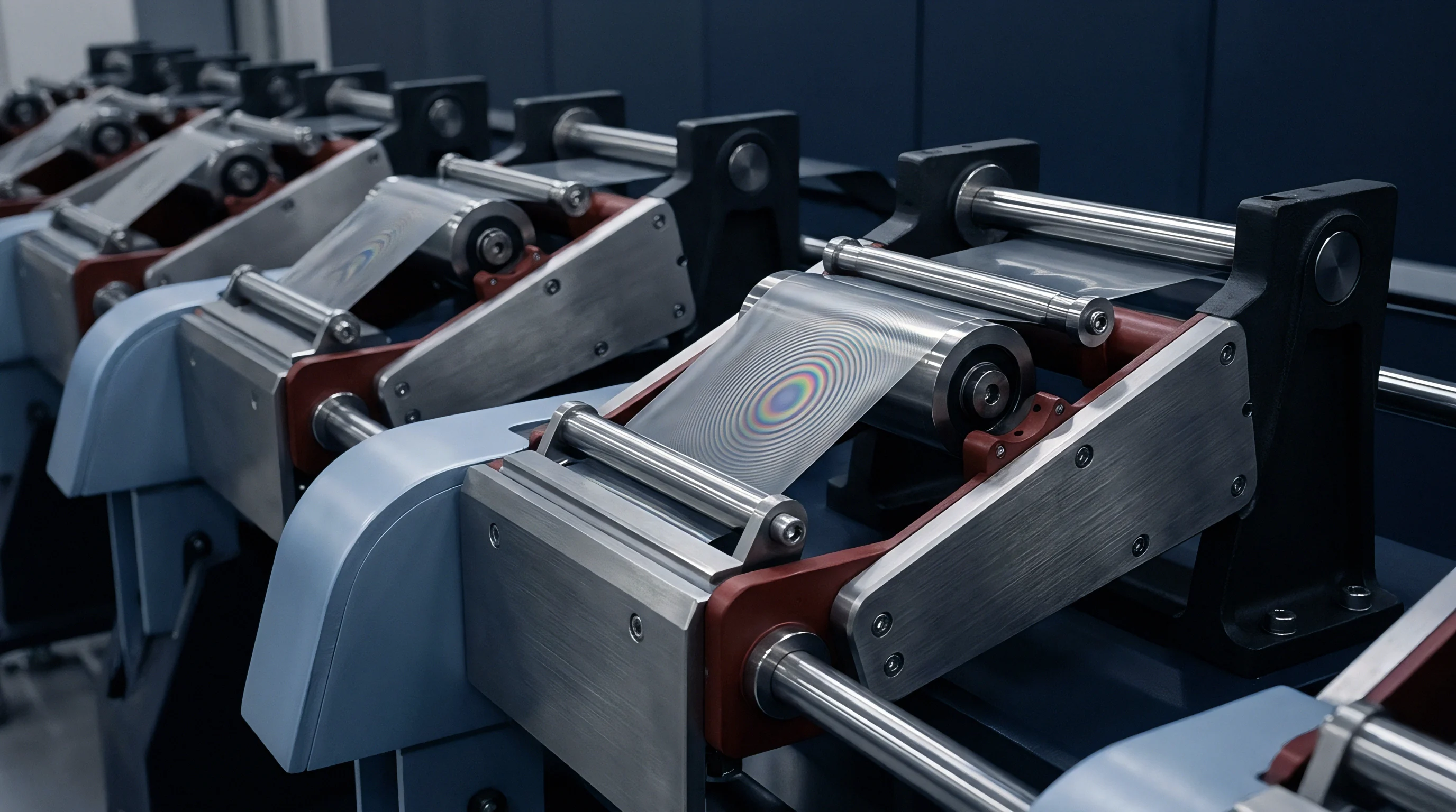
Consider a high-speed slitting line running NMC 811 cathode web on thirteen-micrometer aluminum foil at sixty meters per minute. The line uses a gang-slitting setup with eight lower blades and seven upper blades to produce six individual electrode strips, with a maximum allowable burr height of twelve micrometers.
The setup uses conventional AISI D2 steel blades at 59 HRC matrix hardness. Because of the coarse primary chromium carbides inherent in D2, micro-chipping appears along two upper knife edges after twelve thousand meters. Each chip measures roughly eight micrometers deep and twenty-five micrometers wide.
Every time a chipped section hits the aluminum web, local shear force drops, causing incomplete tearing rather than a clean cut.
Downstream inspection detects periodic burr spikes reaching eighteen micrometers once per blade rotation ~ matching the circumference of the one-hundred-and-eighty-millimeter blades. Without real-time inline laser profile monitoring at every knife station, the defect goes unnoticed for twenty minutes. The financial loss breaks down as follows:
- Production Web Velocity ~ Sixty meters per minute continuously feeding the slitting arbor assembly.
- Defective Run Duration ~ Twenty minutes before offline optical quality audit flags the periodic burr defect.
- Total Scrapped Electrode Length ~ Twelve hundred linear meters of processed cathode web destroyed.
- Coated Cathode Material Cost ~ Calculated at eight point five dollars per linear meter across total web width, yielding ten thousand two hundred dollars in direct material loss.
- Line Reset Down-Time Cost ~ One hour of production halt for blade arbor disassembly, cleaning, re-alignment, and clearance calibration, valued at eighteen hundred dollars per hour.
- Total Single Failure Financial Impact ~ Twelve thousand dollars direct loss from one micro-chipping breakdown event.
Replacing D2 with CPM 10V powder metallurgy steel eliminates coarse chromium carbides and boosts microscopic fracture toughness at the edge. Its fine vanadium carbide structure resists chipping under identical web tension. A CPM 10V blade set reaches fifty-five thousand linear meters before edge rounding slowly pushes burr height toward the twelve-micrometer limit.
While powder metallurgy tooling increases initial blade cost by forty percent, it cuts scrap events by over seventy-five percent per quarter.
Powder metallurgy tool steels with uniform sub-micron carbide dispersions prevent periodic burr spikes caused by structural edge micro-fracture.
Failing to control edge micro-chipping leads directly to severe financial loss through immediate scrap, unscheduled stoppages, and catastrophic cell short-circuit risks downstream during stacking or winding.
Temper
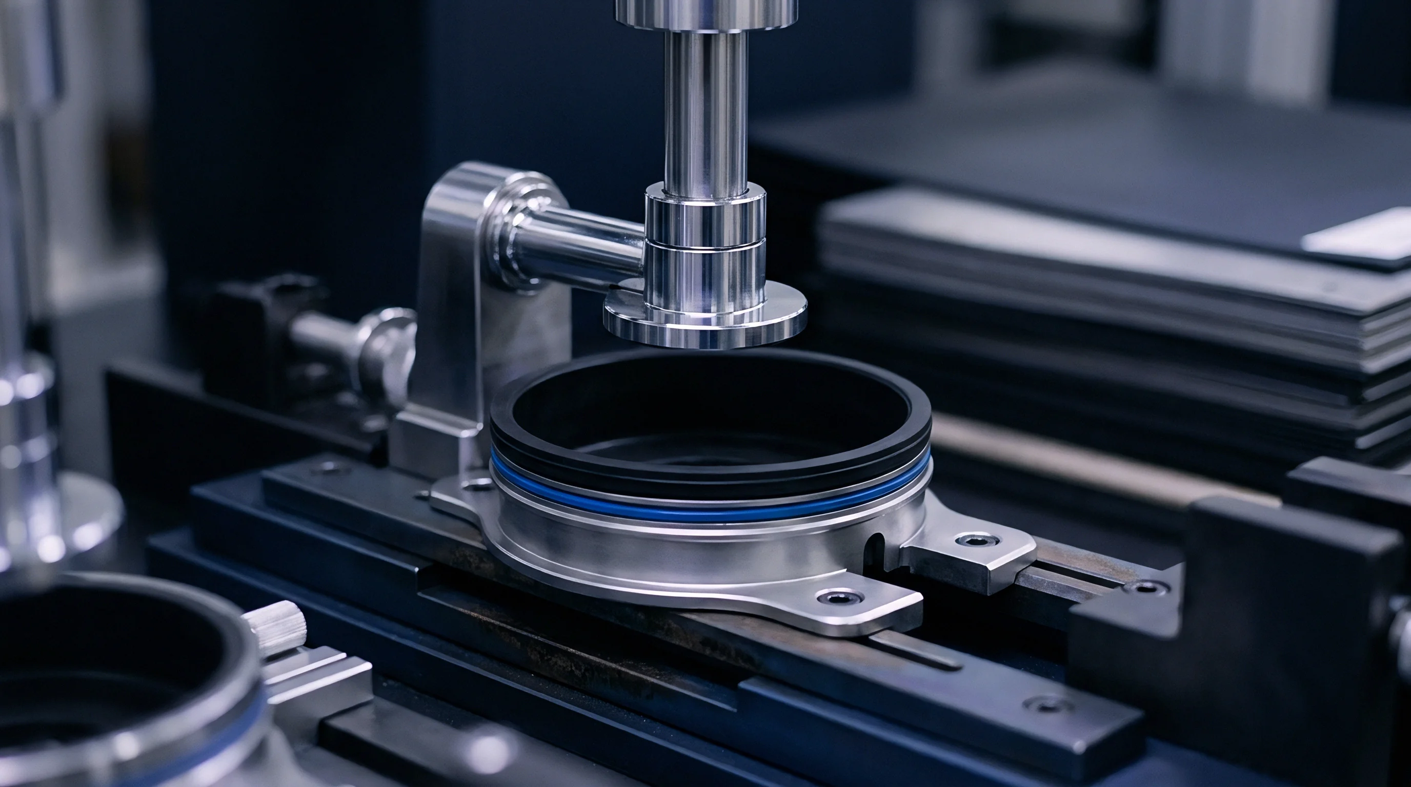
Heat treatment turns soft, annealed blanks into stable, wear-resistant rotary knives. The tools need high surface hardness to resist continuous ceramic abrasion, but also enough core toughness to absorb mechanical shocks along the line. Meeting both requirements in high-vanadium powder metallurgy grades means running vacuum austenitizing, high-pressure gas quenching, and multiple high-temperature tempering cycles to break down retained austenite.
Hardening begins with vacuum austenitizing between 1080°C and 1150°C, depending on the alloy grade. These temperatures dissolve primary carbides into the austenite matrix, enriching the iron phase with carbon, vanadium, molybdenum, and chromium. Soaking time requires careful control: too little time leaves carbon undissolved and lowers matrix hardness, while too much promotes grain growth and reduces fracture toughness.

Retained Austenite Transformation and Cryogenic Processing
Quenching high-alloy tool steels to room temperature converts bulk austenite into untempered martensite. High carbon and alloy concentrations push the Martensite Finish temperature well below room temperature. As a result, standard gas quenching leaves ten to twenty percent of unconverted face-centered cubic retained austenite in the matrix.
Retained austenite is a metastable phase prone to converting over time or under stress. Under operational mechanical pressure, it slowly transforms into body-centered tetragonal martensite. This shift involves a volume expansion of about one to two percent.
On a knife ground to sub-micrometer axial runout tolerances, that localized expansion distorts the blade body and causes lateral runout drift during storage or use.

Does Deep Cryogenic Treatment Eliminate Retained Austenite Drift?
Deep Cryogenic Treatment cools quenched components down to liquid nitrogen temperatures (-196°C) for an extended hold. This sub-zero processing forces the structure past the Martensite Finish point, converting nearly all retained austenite into fresh untempered martensite before tempering.
To achieve maximum structural stability and eliminate dimensional movement over time, tool steel blades follow a strict heat treatment sequence:
- Vacuum austenitizing at target temperature within plus or minus two degrees Celsius under partial pressure nitrogen to prevent surface decarburization.
- High-pressure positive gas quenching with pure nitrogen at six bar pressure down to sixty degrees Celsius to form an initial martensitic matrix.
- Immediate deep cryogenic submersion at minus one hundred and ninety-six degrees Celsius with a controlled cooling rate of one degree Celsius per minute to prevent thermal shock cracking.
- Extended cryogenic hold at minus one hundred and ninety-six degrees Celsius for twenty-four hours to ensure complete conversion of retained austenite down to less than zero point five volume percent.
- Primary high-temperature tempering at five hundred and forty degrees Celsius for two hours to stress-relieve fresh martensite and initiate secondary alloy carbide precipitation.
- Secondary high-temperature tempering at five hundred and forty degrees Celsius for two hours to temper fresh martensite generated during cooling from the primary temper cycle.
- Tertiary high-temperature tempering at five hundred and twenty degrees Celsius for two hours for final structural relaxation and exact hardness targeting within zero point five HRC band.
Triple secondary tempering relies on secondary hardening. In high-vanadium steels with molybdenum and chromium, tempering between 520°C and 560°C precipitates sub-micron secondary carbides from the matrix. These precipitates increase matrix hardness beyond the initial quenched state ~ reaching peak values between 62 HRC and 65 HRC ~ while reducing internal residual stresses.
Skipping deep cryogenic treatment or running only two tempering cycles leaves residual retained austenite above three percent. Over months of storage or thermal cycling on the machine, this untransformed austenite gradually decomposes, creating lateral wobble that ruins tight shear gap settings.
Thermal stability testing measures dimensional movement of finished blades subjected to thermal aging between 20°C and 80°C. Deep-cryogenically treated CPM 10V blades show lateral dimensional changes below zero point one micrometers per one hundred millimeters of diameter. By contrast, non-cryogenically treated blades expand up to zero point eight micrometers over identical test intervals.
Heat treatment parameter choices still leave questions about the exact stress state at the edge after final grinding. High-energy grinding introduces local thermal spikes that can re-temper surface layers or induce phase transformations, leaving residual tensile stresses along the shear edge regardless of cryogenic treatment history.

Grind
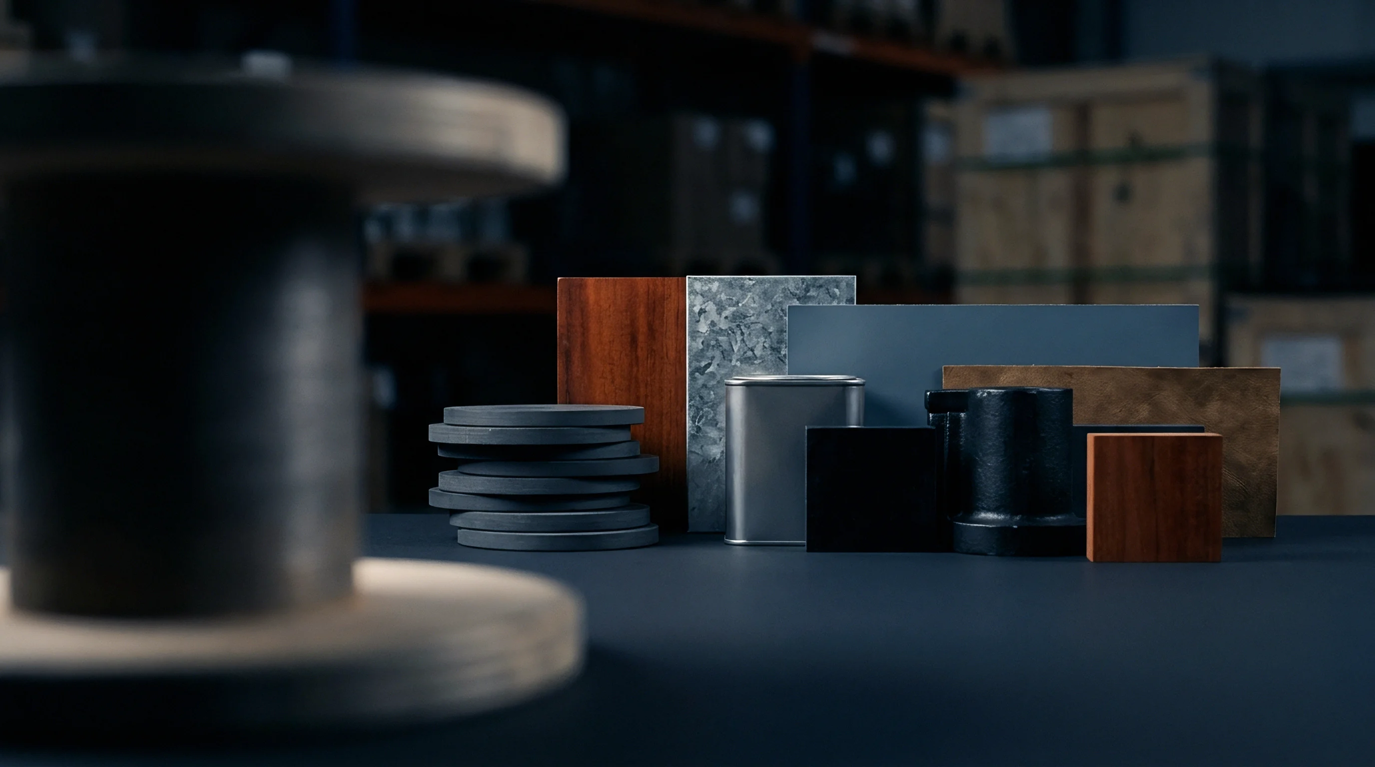
Grinding hardened tool steel blanks into precision cutting discs requires multi-stage grinding with super-abrasive wheels. Grinding defines the functional geometry of the knife ~ establishing plane parallelism, outer diameter concentricity, edge radius sharpness, and surface roughness. Finishing operations must achieve sub-micrometer tolerances to maintain stable cutting dynamics during high-speed slitting.
This degree of geometric accuracy is necessary because shear gaps on modern battery slitting lines are exceptionally tight. A six-micrometer copper substrate demands horizontal shear gaps around zero point six micrometers. If a rotary knife has lateral runout or wobble over zero point five micrometers, the effective shear gap oscillates every revolution, swinging between contact rubbing and excessive clearance.
Geometrical Tolerances and Precision Metric Definitions
Precision manufacturing drawings for rotary shear knives set strict geometric boundaries for key blade dimensions. Deviations directly impair cut quality and shorten tool life.
| Geometrical Feature Parameter | Target Precision Limit | Measurement Method Standard | Operational Consequence of Out-of-Spec |
|---|---|---|---|
| Axial / Lateral Face Runout | < 0.5 µm TIR | Non-contact Laser Interferometry | Shear gap instability, periodic burrs, side rubbing |
| Radial Outer Diameter Runout | < 0.5 µm TIR | High-Precision Air Bearing Spindle Indicator | Variable overlap depth, periodic web tension spikes |
| Face Parallelism | < 0.3 µm total | Sub-micron Optical Flat Gauge | Non-uniform contact pressure against arbor shoulders |
| Cutting Edge Radius r_e | 0.5 to 0.8 µm | White Light Interferometry 100x | Immediate web tearing if > 2.0 µm; edge chipping if < 0.3 µm |
| Clearance Face Roughness Ra | < 0.02 µm | Stylus Profilometry / AFM | Adhesive pickup of copper/aluminum foil particles |
Plane parallelism of the side mounting faces governs how true the blade sits against arbor spacers. If side faces deviate by more than zero point three micrometers, axial clamping force tilts the blade relative to the shaft axis. This angular misalignment translates into amplified lateral runout at the outer cutting edge, causing side-wall interference and rapid wear.
Edge geometry typically uses a single bevel or double bevel profile. Single bevel blades have a flat mounting face and an inclined clearance face angled between thirty and forty-five degrees. The corner formed where the side face meets the bevel does the actual shearing.
The radius of this corner ~ the edge radius ~ determines initial blade sharpness. Uncoated powder metallurgy blades achieve edge radii down to zero point five micrometers when ground with vitrified-bond diamond wheels under controlled oil cooling.

Super-Abrasive Wheel Selection and Surface Integrity
Grinding hardened PM steels with high vanadium carbide fractions requires cubic boron nitride or resin-bonded diamond wheels. Conventional aluminum oxide or silicon carbide wheels dull rapidly because vanadium carbides easily score and fracture softer abrasive grains. Diamond super-abrasives maintain sharp cutting points, slicing through the matrix and vanadium carbides simultaneously without generating excessive heat.
Wheel grit selection follows a multi-step grinding progression. Roughing uses grit sizes from B126 to B46 to establish basic geometry. Intermediate finishing uses fine diamond wheels from B25 down to B15 (FEPA standard).
Final edge honing and face polishing rely on ultra-fine resinoid or polycrystalline diamond slurries on lap plates, using particle sizes down to one to three micrometers.
Coolant delivery and filtration heavily influence surface finish during final grinding. Thermal micro-cracking occurs if grinding fluid fails to flood the contact zone immediately, creating steep thermal gradients in the martensitic steel. Frictional temperature spikes over 600°C locally re-temper surface martensite into soft zones prone to early wear.
Coolant filtration must capture swarf particles down to one micrometer; recirculated steel swarf dragged through the contact zone leaves deep micro-scratches across the polished clearance face.
Edge inspection protocols use white light interferometry or atomic force microscopy to verify edge integrity around the full three hundred and sixty degrees of the knife perimeter. Standard optical microscopes lack the depth of field and resolution to measure sub-micron edge radii accurately. Quantitative edge validation confirms that the edge radius stays within spec while checking for micro-burrs left by grinding wheel exit forces.
Quality management specifications set explicit runout limits:
Standard ISO 286 IT1 grade tolerance limits applied to rotary cutting disc assemblies mandate that total indicator radial and lateral runout must not exceed zero point five micrometers across the complete three-hundred-and-sixty-degree rotational sweep under dynamic operational speed conditions.
If incoming inspection reveals lateral runout over zero point five micrometers on high-speed slitting arbors, the tooling engineering group must reject the lot, as running out-of-spec tools invalidates process capability guarantees and ruins slitting yield targets.

Coating
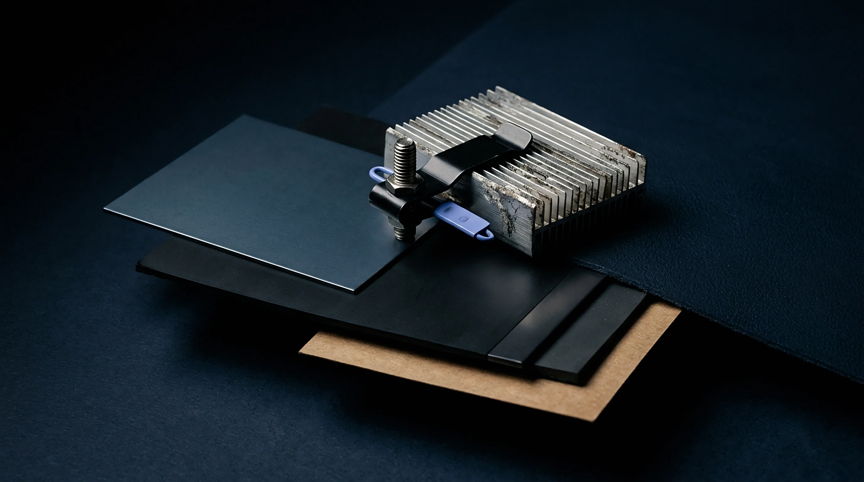
Surface engineering via thin-film Physical Vapor Deposition extends tool life by establishing a micro-hard barrier between the tool steel and the abrasive electrode web. Thin films lower friction against abrasive ceramic powders and prevent direct metal-to-metal contact that causes adhesive copper transfer. However, depositing thin coatings over sharp edges requires tight control over film thickness, residual stress, and deposition temperatures.
Deposition temperatures must respect the tempering history of the underlying substrate. Conventional Chemical Vapor Deposition operating above 800°C ruins heat-treated tool steels, causing core softening and heavy dimensional distortion. PVD processes operating between 350°C and 480°C permit thin-film deposition without exceeding secondary tempering temperatures, keeping substrate hardness above 62 HRC.

PVD Film Formulations and Mechanical Performance
Selecting the right PVD film chemistry requires balancing high nanohardness against low internal compressive stress. Excessive compressive stress can spall coatings along sharp corners, while insufficient hardness fails to protect against micro-abrasion.
- Titanium Aluminium Nitride (TiAlN) ~ High oxidation resistance with nanohardness values between 30 and 33 Gigapascals. TiAlN forms a protective aluminum oxide surface layer during high-speed cutting, effectively resisting abrasive erosion during cathode slitting.
- Aluminium Chromium Nitride (AlCrN) ~ Higher thermal stability and lower thermal conductivity than TiAlN, achieving nanohardness values up to 32 Gigapascals. Excellent resistance against adhesive galling when slitting ductile copper anode foils.
- Diamond-Like Carbon (DLC) ~ Amorphous carbon films rich in sp3 carbon bonds, yielding extreme nanohardness between 40 and 60 Gigapascals with very low friction coefficients against aluminum below zero point one. Film thickness must be kept below two micrometers to prevent high internal stress delamination.
- Nanocomposite AlTiN / a-Si3N4 (nACo) ~ Nanocrystalline AlTiN grains embedded in an amorphous silicon nitride matrix, providing super-hardness exceeding 40 Gigapascals. High toughness prevents crack propagation through the coating layer during dynamic web tension fluctuations.
PVD coatings deposited onto acute knife edges alter the cutting geometry. Standard cathodic arc PVD applies a film thickness between two and four micrometers. Because film growth occurs uniformly around the corner, applying a three-micrometer coating over an edge with an initial radius of zero point five micrometers rounds the final radius up to three point five micrometers.
This rounding significantly increases cutting forces and triggers early burr formation on thin foils.
Overcoming coating-induced edge dulling requires specialized sharp-edge coating protocols. Using Ion-Beam Assisted Deposition or High-Power Impulse Magnetron Sputtering enables thin, dense coatings between zero point five and one point two micrometers thick. Focused ion beam etching prior to sputtering cleans the surface at atomic scales, boosting coating adhesion without dulling the steel edge.
Advanced HiPIMS deposition maintains a final cutting edge radius below one point two micrometers on coated CPM 10V blades.
Scratch testing verifies coating bond strength to the tool steel matrix. Critical load values (L_c) above forty Newtons indicate strong interfacial bonding that can resist shear stresses during continuous slitting. Poor adhesion leads to localized flaking along the bevel, releasing coating debris into the electrode web and exposing the softer steel matrix to accelerated wear.
Coating thickness must never exceed the radius of the underlying ground tool steel edge if acute shear performance is to be preserved.
Substrate preparation is the single most vital factor governing PVD performance; residual grinding stresses or microscopic oil contaminants cause premature spalling regardless of how advanced the chemical formulation is.


Life
Managing precision slitting blades over their lifecycle requires tracking edge decay, quantifying sharpening limits, and establishing clear quality protocols. Refurbishment programs restore worn knives to original geometric tolerances, maximizing total slit distance from high-cost tool steel alloys. A sound lifecycle strategy tracks total cost per linear kilometer of slit web rather than initial tool price.
Edge decay follows a distinct three-stage wear curve during continuous electrode production. Initial primary wear occurs rapidly over the first few thousand meters as sharp microscopic grinding peaks wear down to a stable land. Secondary steady-state wear progresses linearly, maintaining stable cutting forces and acceptable burr heights over long runs.
Tertiary wear sets in when edge rounding passes critical thresholds, driving rapid temperature spikes, exponential friction increases, and severe burrs that force tool retirement.

Sharpness Monitoring and Refurbishment Economics
Inline vision inspection systems mounted directly on slitting frames provide real-time edge quality measurements. Optical linescan cameras capture high-resolution images of the slitted edge, calculating burr height dynamically at line speeds up to one hundred meters per minute. When inline monitoring shows burrs approaching eight micrometers on copper or ten micrometers on aluminum, schedulers flag the knife set for refurbishment during the next batch changeover.
Refurbishment involves disassembling blade arbors, cleaning discs, inspecting structural integrity, and regrinding bevel faces. Precision diamond grinding removes worn material, advancing the bevel face until fresh tool steel forms a sharp cutting corner. Each regrind removes between twenty and fifty micrometers of outer diameter.
Rotary slitting knives have outer diameter grinding allowances that permit multiple refurbishments before reaching minimum dimensions. A knife with an initial outer diameter of one hundred and eighty millimeters can undergo twelve to fifteen regrinds before diameter reduction interferes with overlap adjustments or drive gear ratios. Total lifetime slitting distance for a single CPM 10V blade with scheduled refurbishments exceeds six hundred thousand linear meters of cathode web.
Quality management systems require documentation tracing blade history from raw material billet certification to final scrap disposition. Complete verification dossiers must accompany every tooling lot entering the plant.
Required documentation inside the quality dossier includes:
- Material Test Report ~ Certified ladle chemical composition analysis confirming compliance with target tool steel standards and ASTM E45 cleanliness ratings.
- Heat Treatment Certificate ~ Vacuum cycle temperature logs, gas quench pressure records, deep cryogenic process time logs, and hardness testing reports verifying triple secondary tempering execution.
- Dimensional Inspection Protocol ~ Individual blade measurement reports documenting radial runout, axial runout, face parallelism, and outer diameter tolerances recorded on precision air-bearing measurement stations.
- Edge Geometry Certificate ~ Optical interferometry edge profiles quantifying cutting edge radius and bevel angles across four geometric quadrants.
- Coating Lot Verification Report ~ PVD film thickness measurements, adhesion scratch test data, and surface roughness records for coated blade batches.
- Refurbishment Traceability Log ~ Historical record tracking cumulative re-grind cycles, removed material volumes, remaining outer diameter allowances, and past operational wear metrics.
Comparing overall tooling costs across substrates highlights the economic advantage of powder metallurgy alloys over conventional die steels. While an AISI D2 blade set carries a low purchase price, frequent micro-chipping, high scrap rates, and short total lifespans result in a higher cost per slitted kilometer. CPM 10V or CPM 15V powder metallurgy blades require higher initial investment but deliver three to four times greater slit length per sharpening cycle, significantly lowering manufacturing costs per battery megawatt-hour.
Managing the blade lifecycle also requires systematic tracking of arbor spacer maintenance alongside regrinding schedules. Arbor spacers determine axial positioning and parallel alignment between upper and lower blade sets across multi-strip setups. Spacers made from hardened stainless steel or ceramic materials must maintain face parallelism within zero point three micrometers.
Dirt accumulation, micro-burrs, or excessive locknut torque distort spacers, transferring angular runout directly onto ground knife faces during high-speed runs. Establishing strict ultrasonic cleaning procedures and torque control for arbor assembly prevents alignment errors that ruin knife edges long before normal abrasive wear takes its toll.