Meaning
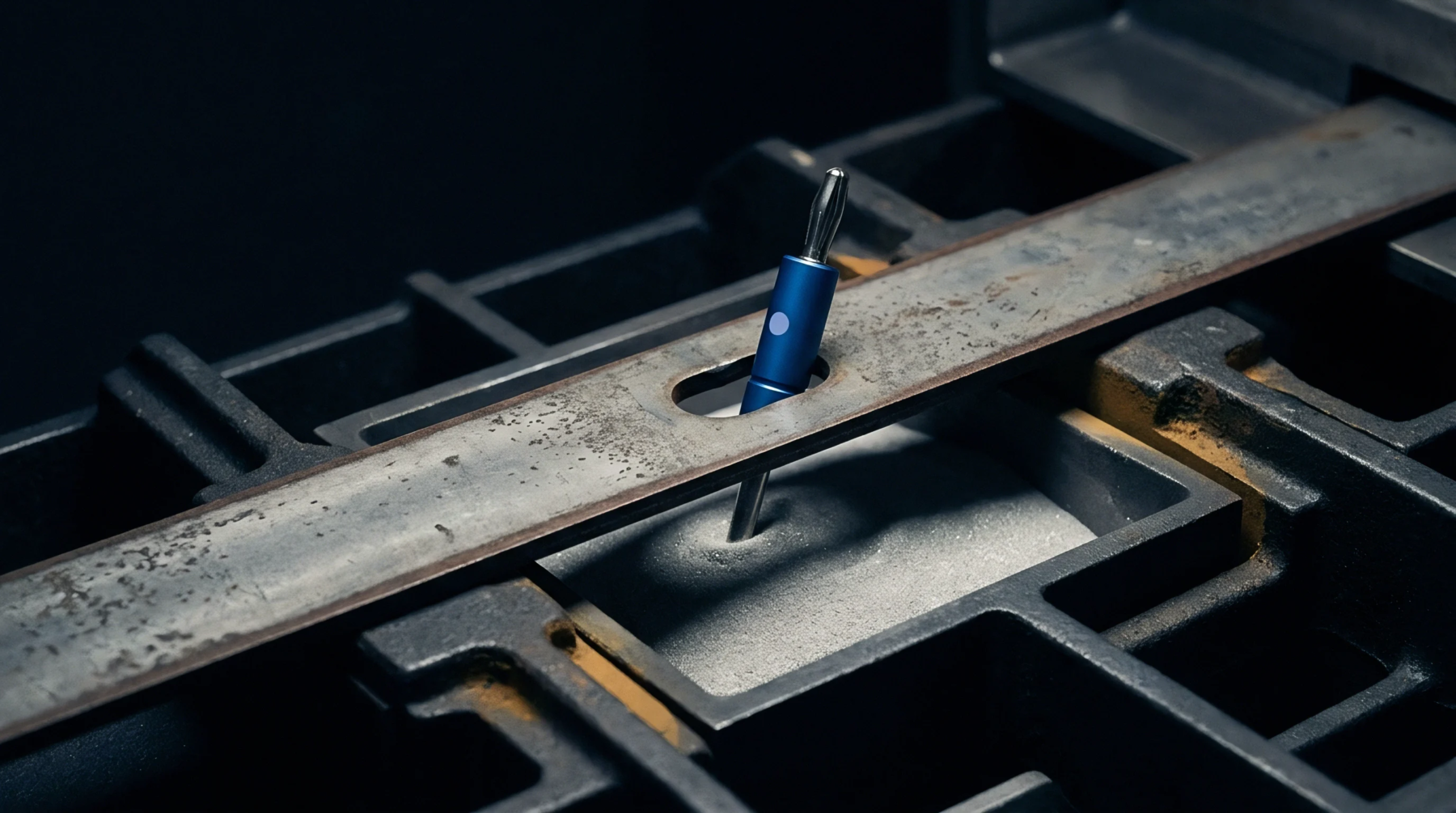
Electrical test configurations utilize a nested arrangement of conductors to measure the resistance of thin film materials. The coaxial probe geometry places a central sensing pin inside a circular outer shield to minimize the effects of external electromagnetic noise. This design is common in high-frequency characterization where the signal must be protected from interference to achieve a stable reading.
Signal Integrity
Maintaining a constant impedance along the measurement path prevents the reflection of the test signal. The coaxial probe geometry ensures that the electromagnetic field is contained within the space between the inner and outer conductors. This confinement is vital when testing the conductivity of battery electrodes at millivolt levels.
Clean signals allow for the detection of subtle variations in the coating quality.
Interference Shielding
Protection from laboratory environment noise comes from the grounded outer shell of the probe. In a busy production facility, the coaxial probe geometry blocks the radio frequency emissions from nearby motors and power supplies. This isolation enables the measurement of low-resistance paths that would otherwise be lost in the background noise.
The grounded shell acts as a continuous barrier against capacitive coupling.
Measurement Accuracy
Consistent contact between the probe and the material surface determines the reliability of the data. Because the coaxial probe geometry provides a defined contact area, the resulting resistance values can be converted into resistivity without complex geometric corrections. Technicians use this data to verify the uniformity of the electrode slurry application across a wide roll.
Reproducible results ensure that every batch of material meets the conductive specifications.