Automated Four Wire Kelvin Probe Testing Fixture Calibration and Maintenance Requirements
Regular calibration and maintenance of automated four-wire Kelvin test fixtures prevent contact resistance drift from mis-grading cell internal resistance.


Contact
Measuring resistance below a milliohm requires total separation between current drive circuits and voltage sensing lines. In high-volume cell production, internal resistance is the main metric used to screen for energy density, power capability, and thermal stability. Automated test systems process thousands of cells an hour, so probe contacts must stay electrically stable through rapid mechanical cycling.
Standard two-wire setups break down at sub-milliohm levels because lead resistance and contact impedance blend directly into the measured signal. A contact interface with even fifty micro-ohms of unstable resistance skews cell grading metrics, masking real defects or flagging good cells as scrap.
Cell internal resistance comprises ohmic and charge-transfer polarization components. Isolating these parameters to check cell health takes either a one-kilohertz AC impedance measurement or a high-current DC pulse test. Four-wire Kelvin probe architectures eliminate parasitic impedance by splitting the terminal connection into two paths: a force circuit to drive excitation current and a sense circuit to measure the voltage drop across the connection.
Because a high-impedance voltmeter draws almost no current through the sense leads, the potential drop across the sense contact interface stays near zero, leaving the measured voltage to reflect only the cell’s internal resistance.
A 50-microohm contact resistance drift at 1 kHz excitation frequency shifts measured battery cell impedance by 12 percent on 0.4-milliohm LiFePO4 cells.
High-speed test fixtures introduce electromagnetic issues that do not show up on static bench setups. Fast mechanical engagement triggers contact bounce, micro-arcing, and brief localized heating at the contact point. High-current DC pulses also generate magnetic flux that links into nearby sense loops.
Unless sense lines are routed as tight coaxial or twisted pairs all the way to the probe block, this inductive coupling creates voltage spikes that distort digital signal processing algorithms.

Kelvin Principle Mechanics in High Throughput Testing
Automated grading equipment sends high AC or DC currents through battery terminals while independent sense lines record true potential drop. The physical placement of the probe tips determines measurement accuracy. Crown and spear geometries break through thin surface oxides on aluminum positive terminals and nickel-plated copper negative terminals.
Force pins deliver current perpendicular to the terminal surface, while sense pins contact the metal within millimeters of that point to limit potential gradients across the terminal face.
Internal resistance directly governs a cell’s high-rate discharge capability.
Incorrect probe spacing distorts the electrical field around the terminal cap assembly. If sense probes touch points too far from the injection site, the measurement captures structural resistance from the terminal plate itself, introducing artificial offsets. Automated fixtures maintain sub-millimeter concentric tolerances between force and sense contacts to keep current paths consistent across every cell in a production lot.

Parasitic Impedance and Sense Loop Geometry
At excitation frequencies like one kilohertz, inductive coupling develops between parallel conductors in the probe block. The loop area formed by force and sense wiring acts like an antenna, picking up noise from nearby linear motors, pneumatic solenoids, and switching power supplies. Keeping this loop area small requires routing sense lines as shielded twisted pairs, separated from current-carrying force cables.
Shifts in contact resistance alter sorting limits and misclassify cells.
Unshielded sense leads running parallel to force cables pick up mutual inductance, injecting a phase-shifted voltage into the sense channel. This shift distorts the real component of AC impedance, causing falsely inflated resistance values during automated cell sorting. High-precision test fixtures place differential sensing amplifiers right on the moving probe head, boosting fragile signals before sending them down drag-chain cables.
| Cell Format | Test Signal Type | Nominal Cell Impedance | Contact Force Target | Max Parasitic Error Limit |
|---|---|---|---|---|
| Cylindrical 21700 | 1 kHz AC-IR | 12.0 to 18.0 mΩ | 1.5 to 2.2 N | 0.05 mΩ |
| Cylindrical 4680 | 100 ms DC-IR (30A) | 0.3 to 0.6 mΩ | 4.5 to 6.0 N | 0.01 mΩ |
| Prismatic LiFePO4 (300Ah) | 1 kHz AC-IR / DC Pulse | 0.15 to 0.35 mΩ | 8.0 to 12.0 N | 0.005 mΩ |
| Pouch Cell (High Power) | 1 kHz AC-IR | 0.4 to 0.8 mΩ | 2.5 to 4.0 N | 0.02 mΩ |
IEC 61960-3 Clause 5.2 mandates four-wire differential sensing to isolate lead impedance during cell AC resistance tests, requiring suppliers to build active contact resistance compensation into automated test systems.


Pin
Pogo probe assemblies undergo hundreds of thousands of engagement cycles on high-volume production lines. Continuous contact with battery terminals subjects probe tips to mechanical wear, friction, and chemical residue. Spring-loaded pins rely on internal sliding contacts to pass current from the moving plunger to the outer barrel.
Over time, plunger wear, spring fatigue, and degraded internal lubricant raise pin resistance, adding noise that compromises cell binning accuracy.
Tip geometry dictates contact force distribution and oxide penetration. Multi-crested crown tips spread pressure across several points, biting through surface oxidation without puncturing thin terminal caps. However, metal particles, crystallized electrolyte, and debris collect in the recesses of crown tips.
As this material builds up, effective contact area shrinks, current density spikes at remaining contact points, and localized micro-welding melts the protective gold plating.
Mechanical sliding gradually wears away surface gold electroplating.
A nickel barrier layer under the gold stops copper from diffusing out of the beryllium copper substrate. Once friction strips the gold, the bare nickel oxidizes quickly in air. Because nickel oxide is far less conductive than gold, contact resistance can jump from a few milliohms to tens of ohms in a few hundred cycles.
Automated fixtures need to track contact resistance baselines continuously to spot pin wear before it impacts production yield.
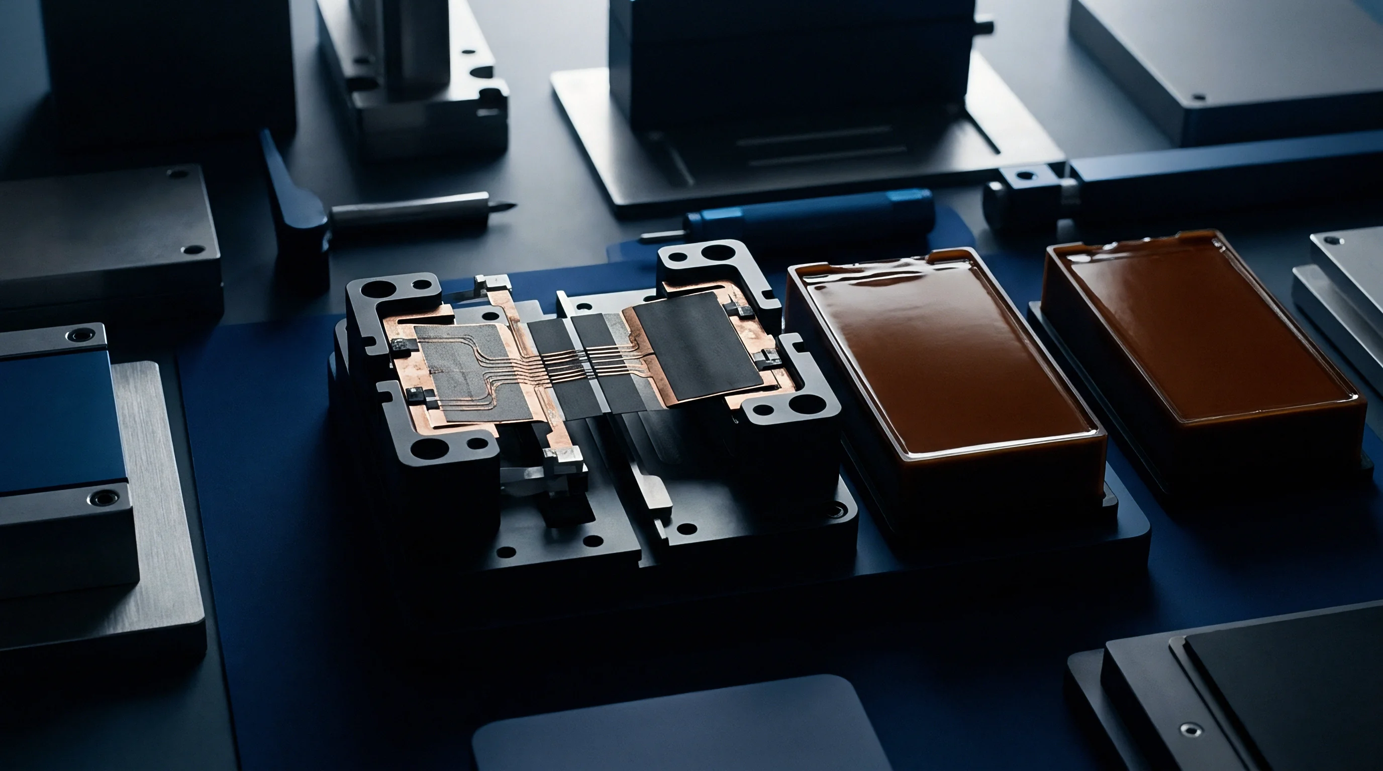
Wear Mechanisms of Plated Test Pins
Coating loss on probe tips stems from localized mechanical friction and concentrated current density. As pneumatic actuators press pins onto cell terminals, small alignment offsets cause minor lateral scraping. This micro-fretting strips precious-metal coatings and exposes the underlying copper alloy substrate to humidity and chemical contaminants.
Worn probe tips change voltage drop readings across the contact point.
High-current pulse testing worsens surface damage. Running 30-ampere pulses through tiny contact points produces rapid thermal expansion that stresses the plating interface. If probes disengage while current is still flowing, micro-arcing erodes metal through localized plasma discharge, leaving microscopic craters that collect non-conductive oxides.
- Gold Layer Erosion Abrasion exposes the nickel underlayer, driving rapid oxidation and causing resistance spikes during voltage sampling.
- Fretting Oxide Buildup Micro-movements form non-conductive debris between the plunger and barrel, leading to intermittent open-circuit voltage spikes.
- Micro-Arcing Cratering Current interruption during probe lift-off pits the tip geometry, creating hot spots and accelerating spring fatigue.
- Spring Stress Relaxation Cumulative thermal cycling and mechanical fatigue lower spring force, preventing probe tips from penetrating surface oxides.
- Alignment Shear Wear Asymmetrical side loading deforms internal probe barrels, leading to mechanical binding and erratic electrical contact.

Structural Fatigue and Tip Contamination Dynamics
Internal helical springs lose compression force over extended operational lifecycles. Lower spring force reduces contact pressure at the terminal, keeping probe tips from breaking through non-conductive surface films. This variation in force causes measured resistance values to fluctuate on consecutive tests of the same cell channel.
Debris build-up acts as an electrical insulator inside probe assemblies. Electrolyte vapors in formation and grading cleanrooms react with ambient moisture to form acidic residues that corrode nickel and copper parts. Dissolved salts settle on probe barrels, increasing internal friction and preventing smooth plunger travel during rapid fixture cycling.
Minor probe tip oxidation is sometimes treated as an acceptable operational tolerance, though it directly degrades cell binning accuracy.


Standard
Calibrating precision electrical test systems relies on physical reference elements with stable, known resistance values. High-volume automated fixtures require regular checks against zero-point references and golden cell standards to maintain accuracy across operating shifts. Calibration procedures establish zero-offsets for parasitic lead resistance, internal instrument drift, and fixture contact impedance.
Master reference standards use low-inductance, four-terminal precision shunts made from specialized copper-manganese alloys such as Manganin or Zeranin. These materials offer near-zero temperature coefficients and long-term resistance stability. Calibration artifacts match the physical shape of production cells so automated handlers can load them using the same mechanical alignment, clamping force, and spatial orientation.
ISO 17025 calibration certification for reference low-resistance artifacts specifies annual re-calibration against primary standards to preserve measurement traceability.
Zero-point calibration removes systematic fixture resistance offsets. Shorting blocks featuring gold-plated copper surfaces establish an ideal zero-resistance baseline. When an automated fixture clamps onto a shorting block, any detected resistance comes from parasitic fixture impedance, wiring, or instrument channel offset.
System software subtracts this offset from cell measurements. If the zero-offset exceeds defined control limits, the system halts operation and flags the channel for maintenance.
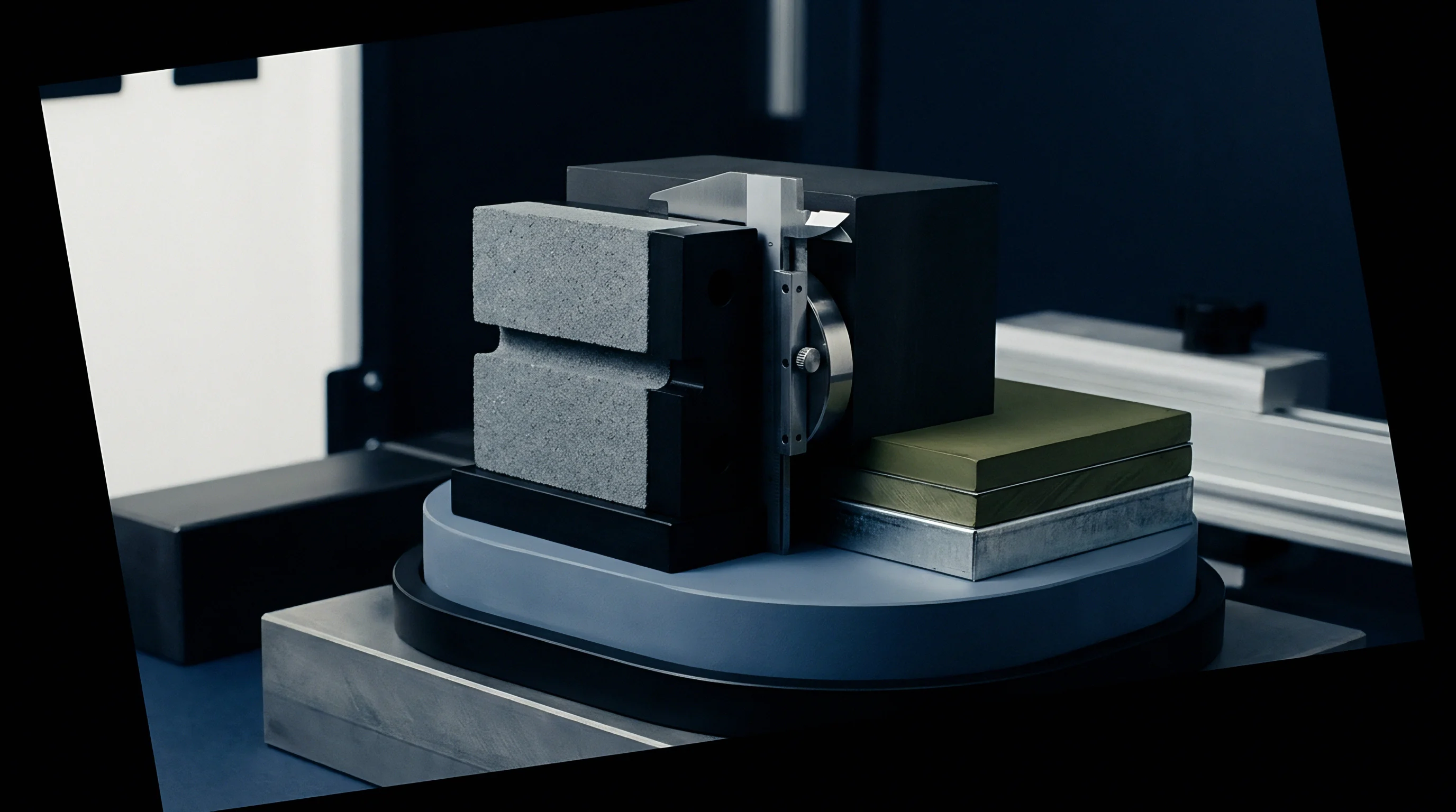
Calibration Artifacts and Reference Resistance Standards
Four-terminal shunts engineered from solid copper or manganese alloys serve as master references for fixture qualification. High-precision shunts are aged to stabilize internal lattice structures and prevent physical drift over years of use. Accredited calibration laboratories certify these resistance values with measurement uncertainties under 0.05 percent.
Reference shunts confirm instrument zero and scale factors.
Calibration artifacts must work across both 1 kHz AC impedance and high-current DC pulse channels. Inductance from wire-wound designs or poor trace layouts distorts 1 kHz AC excitation signals, causing false phase angle shifts. Coaxial or planar strip-line reference shunts maintain pure ohmic behavior up to ten kilohertz, allowing integrated vector impedance analyzers to calibrate accurately.

Temperature Compensation and Fixture Baseline Calibration
Temperature swings on the factory floor directly alter copper trace conductance and probe lead resistivity. Copper has a positive temperature coefficient of resistance of roughly 0.393 percent per degree Celsius. A ten-degree shift in ambient test bay temperature alters probe wiring resistance by nearly four percent, introducing notable measurement error on low-impedance cell sorting lines.
Measuring micro-ohms reliably requires strict thermal stability.
Automated fixtures place digital temperature sensors near probe blocks to enable active real-time mathematical thermal compensation. Calibration algorithms adjust channel offset coefficients based on measured probe block temperatures relative to a 25 degrees Celsius baseline. System software enforces thermal stabilization routines on startup, holding automated cell testing until fixture temperatures reach equilibrium within specified operating bands.
| Calibration Standard Type | Nominal Value | Tolerance | Temperature Coeff. | Recalibration Interval |
|---|---|---|---|---|
| Zero-Point Shorting Block | 0.000 mΩ | ± 0.001 mΩ | N/A (Gold plated) | Daily / Shift Start |
| Low-Impedance Master Shunt | 0.200 mΩ | ± 0.05 % | < 5 ppm/K | Monthly Traceable |
| Mid-Range Reference Standard | 10.000 mΩ | ± 0.02 % | < 2 ppm/K | Quarterly Traceable |
| High-Current Pulse Reference | 1.000 mΩ | ± 0.10 % | < 10 ppm/K | Bimonthly Traceable |
| Values derived from 1 kHz AC-IR and 100 ms DC-IR test channels under controlled ambient temperature of 25 degrees Celsius. | ||||
Uncalibrated reference artifacts at a packaging vendor misclassified an entire container of high-rate lithium iron phosphate cells, resulting in forty-two thousand dollars in rework expenses.
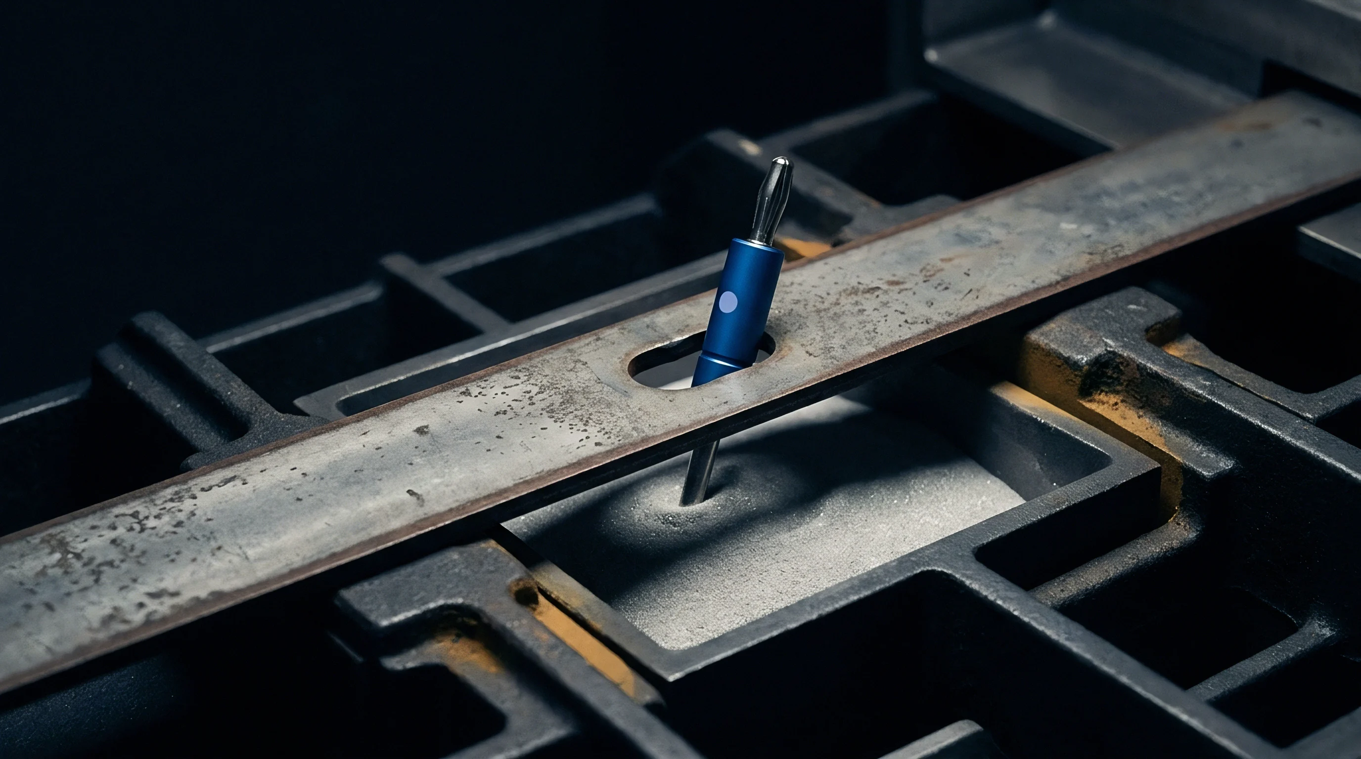

Rig
Mechanical positioning structures determine how consistently probes engage battery cell terminals. Automated grading stations use high-speed pneumatic slides, precision servo-electric actuators, and floating probe holders designed to absorb dimensional variations in mass-produced cells. Poor alignment creates uneven contact force across multi-pin probe clusters, causing localized stress, rapid pin wear, and measurement instability.
Consistent pneumatic force keeps contact resistance stable.
Pneumatic clamping mechanisms supply constant force to drive probe tips through surface oxide layers on cell terminals. Air pressure regulator drift directly alters contact pressure, shifting contact resistance baselines. Load cell force sensors mounted behind probe blocks feed real-time force data back to automated control systems, confirming contact pressure stays within designated windows before triggering electrical measurement hardware.
Pneumatic fixture alignment degrades faster on high-speed lines handling cylindrical cells than on pouch cell lines. Rapid acceleration imposes lateral shear forces on probe guide bushings, introducing mechanical play over millions of stroke cycles. Mechanical play shifts probe land positions away from terminal centers, risking short circuits against outer cell casings or improper contact with non-conductive terminal seal gaskets.

Pneumatic Force Delivery and Alignment Engineering
Pressurized air actuators drive probe carrier blocks down onto stationary battery cell terminals during automated sorting. Air line filtration and precision pressure regulation prevent force fluctuations caused by factory air drops. Proportional valves dynamically adjust actuation force to match specific cell formats, applying lower force to fragile pouch tab foils and higher force to rigid prismatic aluminum terminal posts.
Guidance shafts and linear ball bushings hold alignment accuracy within twenty micrometers. Floating probe mounting plates self-align to accommodate cell height variations resulting from electrode stacking tolerances or casing expansion. Precision alignment pins index into cell carrier trays, ensuring probe tips land on exact target coordinates every cycle.
Maintenance Routines and Cleaning Protocols
Solvent wiping removes non-conductive oil residues and particulate matter accumulating inside probe tip crowns. High-speed automated cell testing transfers drawing lubricants, residual electrolyte, and airborne dust onto probe assemblies. Cleaning schedules must combine automated inline air blowers with manual solvent cleaning using high-purity isopropyl alcohol to preserve low contact resistance.
- Isolate test channel electrical power and shut off pneumatic air before servicing to prevent accidental mechanical movement.
- Inspect probe tips under magnification for gold plating erosion, tip cratering, mechanical bending, or heavy debris packing within crown valleys.
- Use isopropyl alcohol on non-linting swabs to dissolve organic contamination and wipe away loose metallic dust from pin barrels and guide plates.
- Verify pneumatic actuation pressure with an inline digital load cell to confirm contact force falls within specified tolerance limits across all channels.
- Execute automated zero-point calibration and verify master reference shunt measurements against certified values before re-releasing the channel to production.

Fixture Maintenance Thresholds for Sorting Accuracy
Tracking contact resistance variance across consecutive shift cycles establishes clear triggers for mechanical refurbishment. When standard deviation of zero-point calibration measurements doubles relative to baseline values, automated maintenance systems flag probe blocks for pin replacement. Setting statistical control boundaries eliminates subjective maintenance decisions and stops degraded test channels from outputting corrupted cell sorting data.
Replacing probe springs at the first sign of resistance oscillation during pneumatic engagement prevents catastrophic cell binning errors.

Variance
Measurement errors introduced by uncalibrated test channels corrupt internal resistance data recorded during cell binning. Internal resistance sorting boundaries for premium EV-grade lithium-ion cells operate within tight margins, often spanning narrow bands of less than 0.05 milliohms. Uncorrected measurement uncertainty shifts cell populations across sorting boundaries, misclassifying high-impedance defective cells into premium grades or rejecting acceptable production yields into scrap bins.
Uncalibrated test channels corrupt cell binning results.
In audits of cell manufacturing facilities, fixture drift records provide the clearest picture of sorting integrity. A test channel exhibiting unrecognized positive resistance drift systematically understates true cell quality. Cells measured on a drifted channel appear to have higher internal resistance than their actual physical values, pushing good cells into lower performance tiers, reducing supplier margins, and inflating unit landed costs for pack assemblers.
Uncorrected probe resistance drift transforms high-grade low-impedance cells into nominal scrap while passing high-resistance outliers into battery modules.
Negative measurement bias poses an even greater field reliability threat. If a test channel measures cell resistance as lower than actual physical reality, defective cells with elevated internal resistance pass incoming inspection and enter multi-cell parallel module strings. High-resistance cells placed in parallel strings suffer excessive Joule heating under heavy discharge loads, accelerating local thermal degradation and triggering premature battery pack capacity loss.

Financial Mechanics of Measurement Uncertainty
Inaccurate AC-IR values skew cell distribution models and compromise parallel battery module balance. High-power battery packs demand tight resistance matching among parallel-connected cells to prevent localized current crowding. A resistance mismatch of ten percent causes uneven current distribution, forcing lower-resistance cells to supply excess current while higher-resistance cells operate under reduced load.
Uneven current sharing accelerates localized cell degradation.
The financial impact of uncalibrated test channels extends directly to warranty reserves and field return liabilities. If mis-sorted cells cause premature battery pack failure within the warranty window, replacement costs dwarf the minor expense of maintaining calibrated testing fixtures. Sourcing practices must quantify fixture measurement uncertainty to calculate true landed cell risk before approving high-volume supplier purchase contracts.
| Fixture Drift Parameter | Measurement Offset | Yield Impact | Field Failure Risk | Estimated Landed Cost Spike |
|---|---|---|---|---|
| Zero-Point Drift (+0.08 mΩ) | Positive Bias | 8.5 % False Scrap Rate | Low (Over-rejection) | +$0.42 per kWh |
| Contact Resistance Spikes | Random Noise | 4.2 % False Scrap Rate | Moderate (Mis-sorting) | +$0.18 per kWh |
| Uncompensated Thermal Drift | Negative Bias (-0.05 mΩ) | 0.0 % False Scrap Rate | High (Defective Pass) | +$1.65 per kWh (Warranty) |
| Uncalibrated Phase Angle | Impedance Distortion | 3.1 % False Scrap Rate | Moderate (Phase shift) | +$0.25 per kWh |

Statistical Process Control for Test Fixture Drift
Continuous tracking of open-circuit zero offsets and standard reference measurements yields early detection of fixture wear. Automated cell testing lines execute check routines at designated intervals, inserting reference standards into testing stations every two hundred cycles. Statistical process control software plots recorded resistance values on control charts, tracking mean drift and range variance against upper and lower control limits.
Impedance imbalances create uneven load distribution across modules.
Process capability indices like Cpk quantify fixture measurement stability relative to cell sorting specifications. A fixture Cpk value below 1.33 indicates that measurement variance consumes an unacceptably large portion of the cell resistance tolerance window. Automated cell sorting systems lock out channels that breach statistical control limits, enforcing maintenance intervention before corrupted data reaches manufacturing execution databases.
- Statistical Outlier Lockout Automatic suspension of testing channels whose reference shunt readings exceed three standard deviations from historical baseline averages.
- Contact Noise Threshold Enforcement Immediate fixture shutdown upon detecting resistance variance exceeding ten micro-ohms across consecutive measurements on standard artifacts.
- Thermal Drift Limits Programmed lockout triggered when probe block temperature sensors detect ambient temperature swings greater than three degrees Celsius per hour.
- Cycle Count Threshold Interlocks Mandatory physical inspection and cleaning enforced upon reaching pre-set stroke counts regardless of real-time measurement metrics.
- Dual-Channel Difference Checks Cross-channel verification flagging discrepancies between primary AC impedance analyzers and auxiliary DC pulse measurement cards.
It remains uncertain whether high-frequency AC impedance calibration accurately reflects DC pulse resistance degradation under high continuous current discharges.

Audit
Cross-border battery buyers protect cell quality by inspecting test equipment logs and calibration infrastructure at manufacturing plants. Reliance on cell supplier datasheets without verifying production line test fixture maintenance invites substantial quality risks. Sourcing teams perform detailed audits of factory automated testing channels, reviewing calibration certificates, probe replacement frequencies, zero-point baseline tracking, and real-time statistical control logs.
Audits frequently catch uncalibrated test channels in active production.
Factory audits evaluate physical probe fixtures on active production lines. Auditors examine probe alignment tolerances, cleanliness of probe tips, condition of wiring harnesses, and thermal management of measurement blocks. Evaluating supplier equipment reveals whether automated sorting lines maintain true four-wire Kelvin isolation or utilize compromised probe geometries that allow parasitic contact resistance to taint recorded cell data.
Automated sorting lines lacking real-time contact resistance monitoring exhibit double the field failure rate in multi-cell parallel strings due to cell impedance imbalance.
Master cell procurement agreements mandate zero-point baseline validation protocols. Contract terms require suppliers to maintain fully documented traceability for master reference standards back to international measurement institutes. Procurement agreements specify maximum allowable measurement uncertainty limits and define financial penalties for shipments found to contain mis-graded cells resulting from uncalibrated line channels.

Supplier Fixture Qualification and Verification Schedules
Formal evaluation of factory testing channels covers mechanical force repeatability, pin maintenance intervals, and reference master traceability. Suppliers submit comprehensive qualification packages prior to mass production sign-off. The qualification package includes gauge repeatability and reproducibility studies demonstrating that automated test fixtures contribute less than ten percent of total observed process variation during cell resistance sorting.
Routine cleaning extends pin life and delays mechanical replacement.
Verification schedules mandate daily zero-point calibrations, weekly reference shunt checks, and monthly recalibrations of primary measurement hardware. Supplier quality teams maintain digital audit trails recording every calibration event, pin replacement, and fixture lockout episode. Buyer audit teams reserve the right to perform unannounced verification audits, running certified reference blocks through production test channels to confirm fixture accuracy on active assembly lines.

Contractual Terms for Automated Testing Integrity
Clear purchase agreements define acceptable drift limits and standard recalibration frequency for automated cell production channels. Sourcing contracts stipulate that cell sorting data provided in final batch certificates of analysis must derive exclusively from test channels meeting certified capability indices. If auditing reveals uncalibrated test channels on supplier production lines, buyers maintain contractual rights to reject entire manufacturing lots associated with affected testing windows.
- Traceable Artifact Documentation Certified calibration certificates for all physical master shunts and zero-point reference blocks used on production line fixtures.
- Automated Log Submission Raw digital records detailing daily zero-point offsets, channel lockouts, and maintenance interventions for every test channel assigned to order fulfillment.
- Gauge R and R Compliance Reports Experimental evidence proving fixture measurement variance accounts for under ten percent of total cell sorting specification limits.
- Mandatory Maintenance Schedules Documented Standard Operating Procedures defining probe cleaning protocols, load cell verification steps, and mechanical replacement thresholds.
Continuous automated monitoring of test fixture resistance paired with strict contractual recalibration triggers ensures that incoming battery cell lots meet tight internal resistance specifications before module assembly.