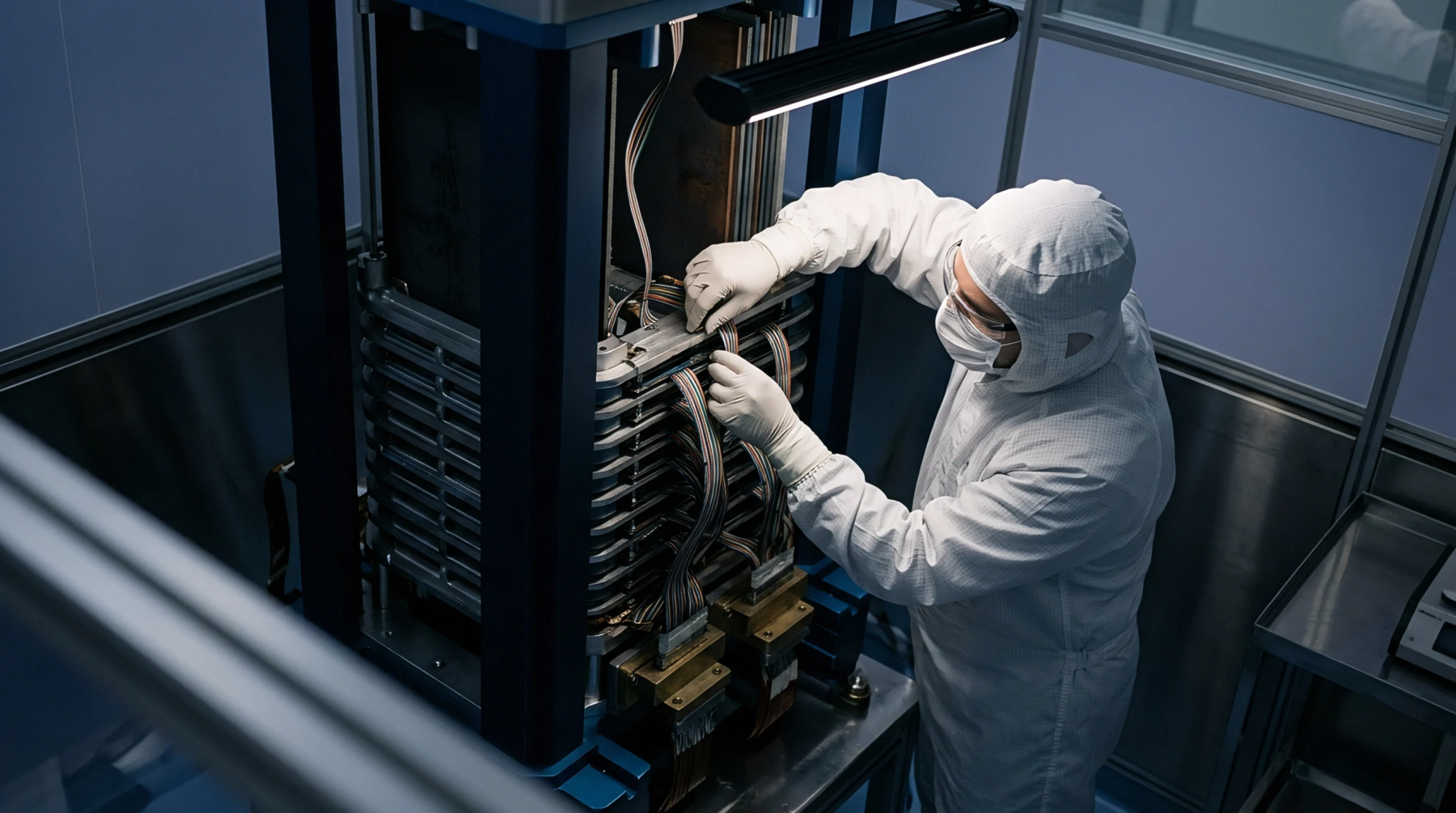
Coupled Thermomechanical Degradation and Structural Clamping in Large Format Cells
Mechanical pre-load between 0.2 and 0.5 MPa optimizes cycle life by preventing graphite delamination while maintaining pore network ionic diffusivity.
Structural containment housing surrounds and mechanically secures an array of interconnected electrochemical cells within an energy storage system. Fabricated from stamped steel, extruded aluminum alloys or reinforced composite polymers, this assembly serves as the primary boundary providing structural rigidity, physical positioning and environmental shielding for internal cell matrices. The module enclosure resists cyclic mechanical forces induced by electrochemical cell swelling, carries integrated cooling interfaces and provides mechanical points for pack-level mounting.
Its definition stops at the boundary of individual cell groups, distinguishing it from full battery pack housings that incorporate master disconnects, high-voltage battery management systems and vehicle-level mounting frames. Sourcing specialists review enclosure drawings for weld integrity, structural stiffness limits, dielectric coatings and thermal performance tolerances.
Rigid exterior walls resist substantial internal pressures generated by dynamic and calendar cell expansion. When prismatic or pouch cells are charged, active material dilation attempts to expand the stack outward along its longitudinal axis. Strong end plates connected through tensile side bands or structural baseplates constrain this motion, converting displacement into beneficial interfacial pressure that preserves active layer contact.
Finite element analysis validates that enclosure wall deflection remains below millimeter thresholds under worst-case end-of-life swelling conditions. Inadequate enclosure stiffness allows excessive displacement, which stresses internal electrical interconnects and leads to busbar fatigue cracking.
Heat rejection paths within the structure govern cell operating temperatures and minimize internal thermal gradients. Module enclosures integrate flat thermal interface plates along their bottom or side profiles, allowing direct contact with pack cooling circuits or embedded internal liquid channels. Precision geometric tolerances must be maintained during enclosure manufacturing to prevent gaps between cell surfaces and thermal interface materials, as air gaps introduce significant thermal resistance.
High thermal conductivity aluminum alloys are widely specified to transfer waste heat efficiently away from the center of the cell block toward active cooling loops. Thermal barrier coatings are simultaneously applied to perimeter surfaces to suppress unwanted heat transfer between adjacent modules during abnormal thermal events.
Dielectric isolation barriers applied to interior enclosure surfaces prevent catastrophic short circuits between high-voltage busbars and chassis ground. Manufacturing operations apply electrostatic powder coatings, pet films or composite sheet liners over raw metallic walls to ensure continuous electrical clearance and creepage requirements are met. Enclosure joints must also accommodate safe venting conduits to direct dangerous off-gas away from sensitive module electronics if cell thermal runaway occurs.
Module enclosure specifications dictate flame retardant classifications and rigorous dielectric breakdown voltages to satisfy international electric vehicle safety standards.
Mechanical pre-load between 0.2 and 0.5 MPa optimizes cycle life by preventing graphite delamination while maintaining pore network ionic diffusivity.
Expertise is a utility, not a secret. sentiention™ publishes its working knowledge as open reference: intelligence layer covering the materials it sources, the markets it enters, and the reference that serves both.