Module Level Thermal Dissipation and Mechanical Clamping Optimization Mechanics
Optimizing module heat dissipation demands matching thermal interface wet-out and structural clamping spring rates to compensate for cyclic cell expansion.

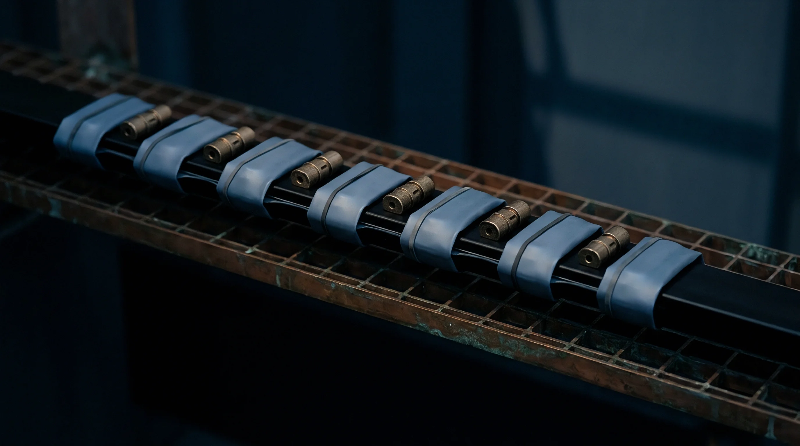
Gap
Rejection of heat across the interface in high-energy battery modules depends on maintaining continuous contact across microscopic surface asperities between cell casings and cooling plates. Dimensional variations in extruded aluminum prismatic cells, cold plates, and structural framing leave inconsistent gaps across mating surfaces. Mounting metal directly to metal without elastomeric fillers traps air across ninety percent of the nominal contact area.
Air carries a thermal conductivity of only 0.026 W/(m·K), creating a severe thermal barrier that drives up local temperatures during high discharge rates. Bridging these voids requires interface materials that conform under moderate clamping force while preserving low thermal impedance across operating temperature ranges.
Total impedance through a thermal interface material breaks down into two resistances in series: bulk thermal impedance of the material itself and contact resistance at the boundaries. Bulk thermal conductivity between 1.5 W/(m·K) and 6.0 W/(m·K) controls internal heat flow, while surface wetting governs boundary contact. Higher loadings of alumina, boron nitride, or aluminum oxide particles raise bulk conductivity, but they stiffen the compound and increase viscosity.
Liquid phase-change materials lower initial contact resistance by melting between 45°C and 55°C, spreading into micro-voids under clamping pressure. Dispensable liquid fillers conform more readily than pre-cured elastomeric pads, taking up planar variations up to 1.2 mm without putting excessive stress on thin pouch or prismatic cell walls.
At a clamping pressure of 0.30 MPa, liquid silicone gap fillers achieve an interfacial thermal resistance below 0.45 cm²·K/W across a 0.20 mm tolerance band.
How a material deforms under compression dictates how thick it needs to be when designing a module. Compressive force flattens out surface peaks, deforming the material and thinning the bond line. Elastic silicone pads need continuous compression of twenty to forty percent of their uncompressed height to perform effectively.
Squeezing elastomeric sheets past fifty percent deformation can buckle cell walls and squeeze out silicone oil, which degrades long-term dielectric breakdown voltage over time.

Thermal Interface Material Impedance Breakdown
Bulk thermal resistance scales directly with thickness and inversely with contact area. Below a bond-line thickness of 0.15 mm, contact resistance takes over total thermal impedance as microscopic roughness dictates the heat path. High-viscosity liquid compounds require precise dispense patterns to prevent trapping air during module assembly.
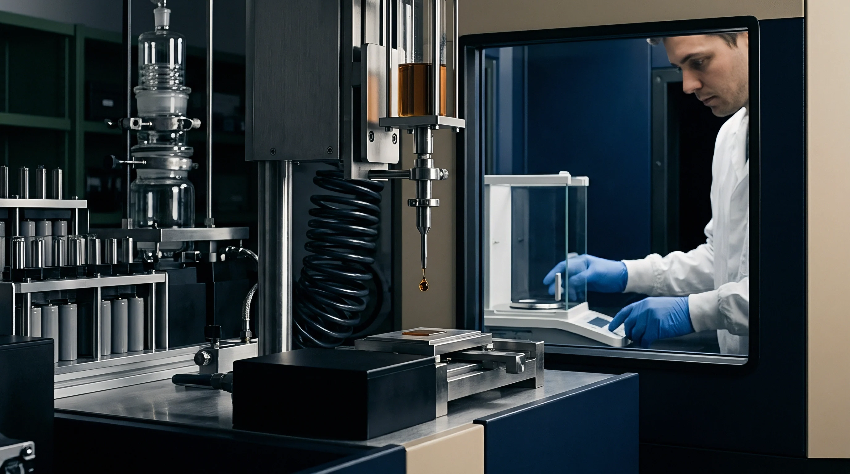
Automated systems lay down cross-hatch, serpentine, or parallel beads to ensure the material wets out evenly without leaving isolated voids.
Dielectric insulation must be evaluated alongside thermal performance to prevent shorting between cell canisters and grounded aluminum chill plates. Standard gap-filling elastomers deliver dielectric breakdown strengths between 8 kV/mm and 12 kV/mm. Cyclic shear stress from mismatched thermal expansion among steel frames, aluminum cold plates, and plastic cell holders can degrade dielectric films over time.
Evaluating interfacial thermal impedance across five distinct surface roughness profiles establishes minimum dispense volume targets.

Surface Flatness and Roughness Tolerance Stacks
Tolerance stack-ups across long prismatic cell strings accumulate substantial mechanical variation over the length of a module. Machined cold plates typically hold flatness within 0.10 mm per 100 mm run, but structural welding introduces distortion up to 0.50 mm across the finished bed. On top of that, prismatic cell bases can bow convex or concave by up to 0.35 mm after formation filling and sealing.
Adding these variations together defines the maximum gap an interface material must bridge without trapping dry air.
Surface roughness measured in Ra and Rz metrics quantifies the microscopic peaks and valleys on mating aluminum surfaces. Standard extruded aluminum cold plates give Ra values between 1.6 µm and 3.2 µm, which take soft, conformable compounds to fill the tiny voids. High-pressure die-cast aluminum surfaces are rougher, often exceeding 6.3 µm Ra, requiring thicker dispensable fillers or soft pads with low hardness ratings between Shore 00 30 and Shore 00 60.
| Material Architecture | Bulk Conductivity (W/m·K) | Optimal Pressure (MPa) | Thermal Resistance (cm²·K/W) | Minimum Thickness (mm) | Dielectric Strength (kV/mm) |
|---|---|---|---|---|---|
| Silicone Gap Pad (Pre-cured) | 3.0 | 0.35 | 1.10 | 0.50 | 10.0 |
| Acrylic Non-Silicone Pad | 2.5 | 0.40 | 1.35 | 0.50 | 12.0 |
| Phase Change Elastomer Sheet | 4.5 | 0.20 | 0.30 | 0.12 | 8.5 |
| Two-Part Dispensable Liquid Silicone | 3.5 | 0.15 | 0.45 | 0.20 | 11.5 |
| Compressible Polyurethane Foam Pad | 1.2 | 0.50 | 2.10 | 1.00 | 6.0 |
| Data measured at 25°C baseline ambient temperature under steady-state heat flux of 50 W/cm² according to ASTM D5470 test conditions. | |||||
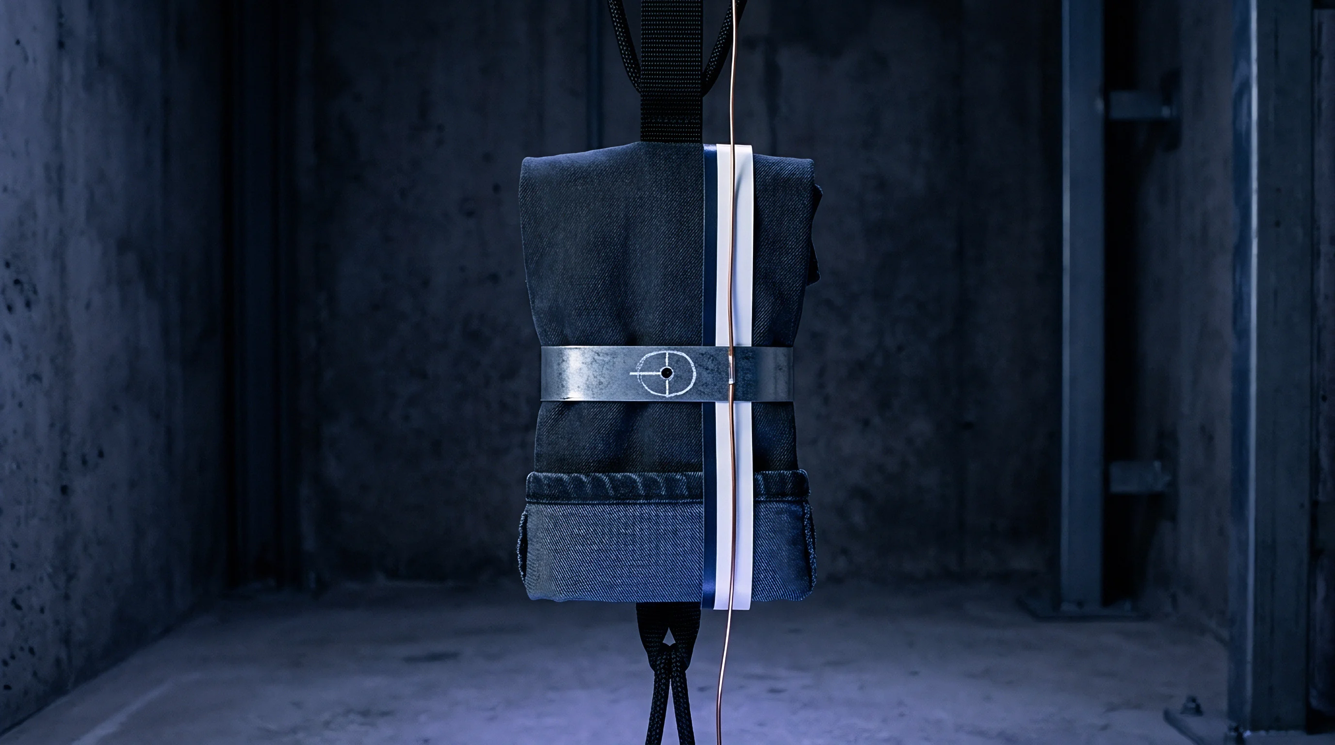
Compressive Deflection Characteristics under Assembly Stress
Polymeric gap fillers show non-linear stress-strain curves under compression during module assembly. Initial low-force compression causes quick displacement as polymer chains align. As compression continues, ceramic filler particles interlock within the silicone matrix, sharply increasing resistance to further displacement.
Setting clamping preloads within this steep transition zone risks high loads that can distort thin aluminum cooling channels.
Automated assembly presses regulate force to avoid structural damage while ensuring complete wet-out. Real-time force-displacement monitoring during insertion flags fill volume errors, dry spots, or cell misalignment before curing starts. Dispense variations beyond five percent alter stress distribution across cell walls, creating local pressure points that accelerate degradation during cycling.
Improper interface thickness directly compromises module reliability. Excess thermal resistance lets cell temperatures exceed critical limits during peak loads. Temps above 55°C accelerate solid electrolyte interphase breakdown, causing rapid capacity loss and severe thermal gradients across cell strings.
Undersized gaps cause direct mechanical interference, cracking ceramic isolation layers, creating immediate chassis grounds, and driving up scrap during high-pot testing.


Preload
Applying continuous compression across a battery cell stack holds the structure together and counters internal pressure built up during lithium intercalation and deintercalation. Graphite anode layers expand by up to ten percent during charging, driving physical swelling across both prismatic and pouch cells. Left unconstrained, these expansion cycles cause active material to delaminate from current collector foils, spiking internal ohmic resistance and cutting cycle life short.
Precision clamping keeps compressive pressure within target bounds across the full state-of-charge range and service life.
Setting target compression limits means balancing active material stability against structural yield limits of module components. Minimum mechanical pressure, usually set between 0.15 MPa and 0.30 MPa for prismatic formats, keeps internal layers from separating and prevents gas pockets from moving in pouch cells. Upper limits should not exceed 0.80 MPa to 1.20 MPa when fully charged late in life.
Going over these pressures crushes separator pores, restricting lithium ion transport and causing metallic lithium plating on graphite anodes during fast charging.
Compliance with UN 38.3 T4 mechanical shock testing mandates that mechanical retention frame deflection remains within 0.15 mm under a 50g peak acceleration pulse.
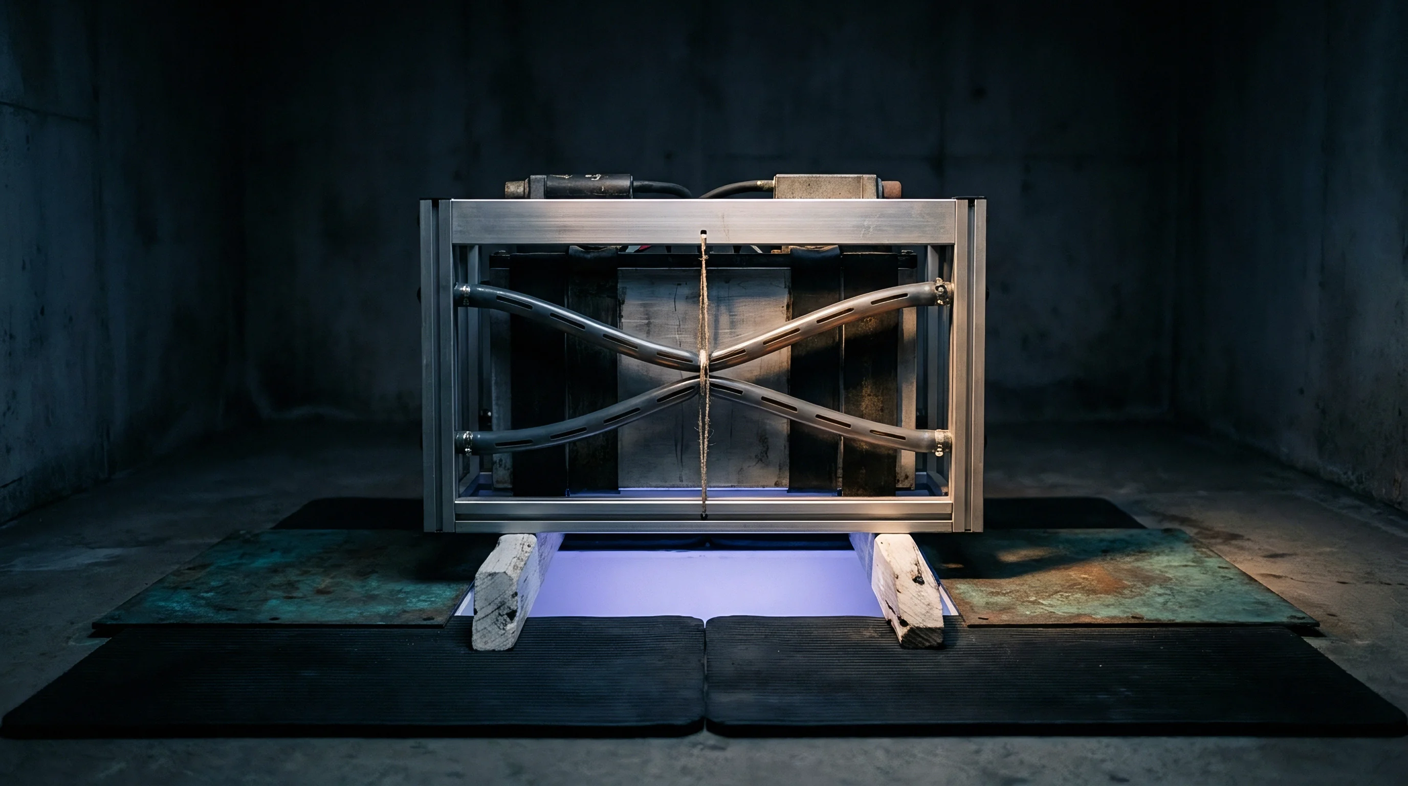
End plates, side straps, and tie-rods translate initial bolt torque or strap tension into uniform planar compression across the stack. End plates need tailored stiffness profiles to spread loads evenly over cell faces. Thin aluminum end plates tend to bow outward at the center, concentrating high stress along cell edges while leaving the center under-restrained.
Adding structural ribs or parabolic face profiles keeps plates flat under peak end-of-life expansion forces.

Initial Assembly Compression versus End-of-Life Expansion Pressure
Managing module stress requires accounting for the dimensional shift between new, uncycled cells and aged, swollen ones. Fresh cells sit at their minimum thickness and need accurate initial preloads to seat thermal interfaces without crushing compression foams. Over three thousand cycles, solid electrolyte interphase growth, oxidation, and gassing cause cells to permanently expand by two to six percent.
Structural frames must accommodate this growth without exceeding tensile limits.
Placing compressible polyurethane or silicone foam pads between adjacent cells adds compliance to an otherwise rigid stack. These foam layers act as springs in series with the expanding cells, absorbing swelling and tempering peak stresses. Choosing foams with flat stress-strain plateaus across their working deflection range keeps internal pressure stable even as cell thickness grows.
- Position target battery cells into precision alignment fixtures to lock terminal positions and maintain planar parallelism across the module stack.
- Place calibrated compressible foam interlayers between individual cell faces to establish distributed mechanical spring elements across the cell string.
- Install structural end plates and side enclosure panels, engaging guide pins to prevent shear load transmission into cell casings during loading.
- Apply controlled hydraulic compression across structural end plates until reaching target initial clamp load within a two percent force tolerance band.
- Torque structural tie-rod fasteners or execute high-energy laser welds along side retaining straps while under active hydraulic press load.
- Release hydraulic press pressure slowly while logging load retention cells to verify residual static friction and structural frame elastic springback.
Structural Frame Deflection and Tie-Rod Stress Mechanics
Side straps and longitudinal tie-rods carry continuous tensile loads driven by expanding cell stacks. Structural steel or high-strength 6061-T6 aluminum alloys are chosen for these members because of their high elastic modulus and predictable creep resistance under thermal load. Sizing tie-rods requires factoring in differential thermal expansion among aluminum cold plates, steel side straps, and plastic cell frames across temperatures from -40°C to +85°C.
Threaded fasteners lose preload over time through joint embedding, thread micro-yielding, and foam creep. Placing Belleville disc spring washers under bolt heads maintains axial compliance, absorbing thermal growth while preserving minimum bolt tension. Tie-rod stretching must stay well within the linear elastic range to prevent permanent frame deformation that would drop stack compression at lower states of charge.

Pouch and Prismatic Cell Swelling Force Evolution
Pouch cells are mechanically far more compliant than rigid aluminum prismatic cans, so internal gas and electrode swelling show up directly as surface displacement. Their flexible walls require steady, even pressure across the face to maintain contact with inter-cell cooling plates. Prismatic cells use thick aluminum walls that contain internal forces up to their yield point, though long-term cycling eventually causes central face bulging that concentrates stress against surrounding components.
Modeling cell swelling forces requires combining reversible electrochemically driven expansion with permanent aging growth. Reversible swelling tracks state of charge, rising during lithium intercalation and falling on discharge. Permanent swelling accumulates over years of operation, driven by temperature history, average state of charge, and cumulative throughput.
Retention frames must be designed for peak combined swelling forces at one hundred percent state of charge at end-of-life.
Capacity-loss warranty claims frequently center on non-compliant structural expansion limits and failure to maintain required planar contact pressure over time, complicating performance degradation liability.
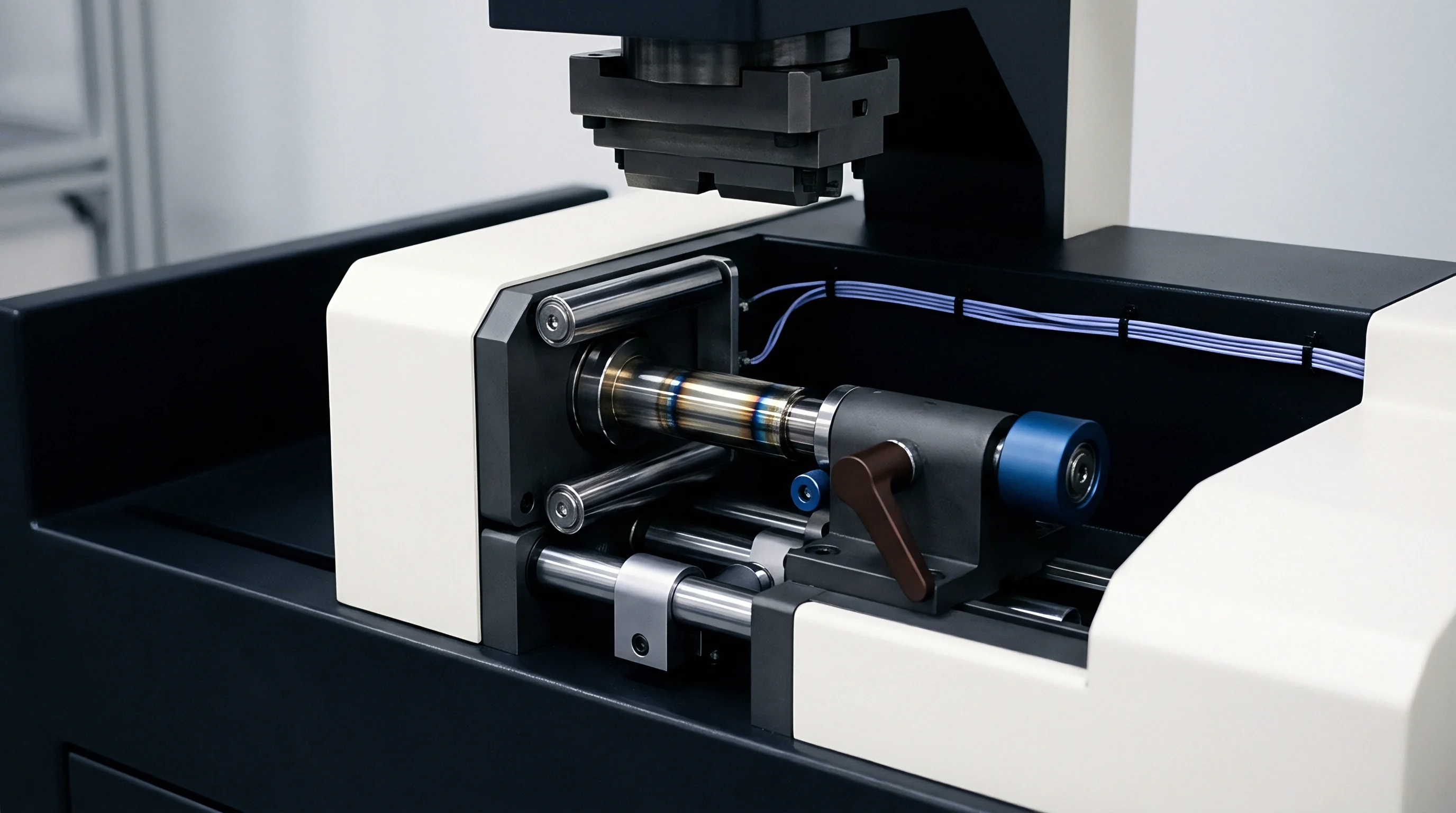

Conductance
Heat transfer from internal electrode structures to external liquid coolant involves a series of conductive and convective steps. Heat generated in current-collector foils and active coatings moves through separators, cell walls, thermal interface materials, and cold plates before entering the fluid loop. Maximizing conductance through this stack reduces core-to-surface temperature gradients, keeping peak cell temperatures within safe limits during high C-rate discharges.
In-plane heat conduction parallel to current collector foils is an order of magnitude higher than conduction through the electrode stack. Copper current collectors offer thermal conductivity near 385 W/(m·K), while organic separators soaked in electrolyte yield less than 1.0 W/(m·K) through their thickness. Because of this, tab- and edge-cooling pull heat along high-conductivity internal pathways much more effectively than surface cooling, reducing internal temperature gradients during fast charging.
Liquid cold plates operating at 10 liters per minute achieve convective heat transfer coefficients exceeding 4,500 W/(m²·K) using ethylene glycol water mixtures.
Heat transfer efficiency in liquid cold plates depends on channel geometry and boundary layer control. Micro-channel plates split fluid into numerous parallel, high-aspect-ratio streams, increasing wetted surface area and thinning the thermal boundary layer. However, the higher hydraulic resistance increases pump pressure drop and parasitic power draw.
Optimization comes down to balancing heat transfer capability against pumping losses.

What Interface Thickness Minimizes Contact Resistance?
Minimizing resistance across an interface layer requires thinning the bond line while applying sufficient pressure. Contact resistance drops sharply as pressure flattens surface peaks and forces the material into microscopic valleys. Below roughly 0.10 mm, ceramic filler particles inside gels begin to interfere with each other, resisting further compression and spiking mechanical stress on cell casings.
Thicker interface layers elevate cell temperature.
Thermal transport modeling of elastomeric pads under varying compression levels identifies where surface wet-out ends and particle jamming begins. Optimal thermal performance occurs when pressure displaces air from the surface without squeezing fluid away from filler particles. Thermal grease pump-out leaves severe voids.
- Interfacial Pump-Out Failure occurs when differential thermal expansion between cell walls and cold plates repeatedly flexes the gap, pumping low-viscosity compounds outward and leaving air-filled voids at the center.
- Phase Separation Degradation occurs when sustained pressure squeezes liquid silicone carrier oil out of the bulk material, leaving unbonded ceramic particles that crack under vibration.
- Silicone Volatile Outgassing releases low molecular weight siloxane vapors at high temperatures, which condense on electrical contacts to form insulating silica films across high-voltage busbars.
- Thermal Interface Cracking develops when rigid, two-part dispensable epoxies experience cyclic thermal shear, creating structural fractures across the heat conduction path.

Cold Plate Heat Transfer Coefficients and Coolant Channel Fluid Dynamics
Convective heat transfer inside cold plates depends on Reynolds number, Prandtl number, and hydraulic diameter. Low flow rates result in laminar flow, giving modest heat transfer coefficients between 500 W/(m²·K) and 1,200 W/(m²·K). Pushing into turbulent flow drives coefficients above 5,000 W/(m²·K), but increases pressure drop sharply across the circuit.
Adding internal pin fins or dimpled turbulence promoters disrupts boundary layers at moderate velocities, raising heat transfer without needing excessive pump power.
Coolant selection directly affects heat transfer performance and pumping demands. A fifty-fifty water-ethylene glycol mix protects against freezing down to -37°C, but has a lower specific heat capacity and higher viscosity than pure water. At sub-zero temperatures, that increased viscosity can raise pressure drops by up to four hundred percent during cold starts, requiring larger channel cross-sections or bypass loops.
| Plate Architecture | Heat Transfer Coeff. (W/m²·K) | Pressure Drop (kPa) | Coolant Volumetric Flow (L/min) | Target Heat Rejection (W) | Weight Penalty (kg) |
|---|---|---|---|---|---|
| Extruded Micro-channel Aluminum | 4,800 | 42.0 | 8.0 | 2,500 | 3.20 |
| Stamped Blister Plate (Two-Piece) | 2,200 | 12.5 | 8.0 | 1,400 | 1.85 |
| Machined Friction Stir Welded Plate | 5,500 | 58.0 | 10.0 | 3,200 | 4.10 |
| Die-Cast Pin-Fin Array Plate | 3,600 | 28.0 | 8.0 | 2,100 | 2.75 |
Transient Heat Generation during Peak C-Rate Discharges
Heat generation inside a battery cell combines irreversible Joule heating from internal resistance with reversible entropic heating from phase transformations. Joule heating scales quadratically with current (I²R losses), dominating thermal output during fast charging and hard acceleration. Entropic heating varies linearly with current and can change sign depending on reaction direction and lithium concentration in the electrode matrix.
High-power 10C discharge pulses create thermal spikes that temporarily outpace steady-state cooling capacity. During these transients, the thermal mass of internal cell components and aluminum plates acts as a buffer, soaking up heat while temperature waves diffuse through thermal interface layers. Designing cooling systems solely for steady-state operation can allow internal core temperatures to exceed safe limits long before coolant temperature registers a rise.
Thermal interface stability criteria are explicitly referenced in IEC 62619 vibration testing standards. Compliance requires that thermal resistance changes stay within a fifteen percent margin of initial baseline values after exposure to continuous random vibration. Interfacial voiding accelerates thermal runaways.

Fatigue
Repeated mechanical and thermal cycles cause gradual degradation in module framing, interface layers, and clamping hardware over battery service life. Thermal cycling drives differential expansion between dissimilar materials, inducing cyclic shear across bonded joints and fasteners. At the same time, road vibration sends dynamic acceleration loads through mounting brackets, exciting natural frequencies and threatening structural integrity.
Viscoelastic relaxation in polymeric gap fillers and side pads leads to lost clamping pressure over time. Under continuous load, polyurethane and silicone foams undergo polymer chain realignment, permanently reducing the back-pressure applied to cell faces. This creep reduces interfacial contact force, allowing thermal interface bond lines to detach or form micro-voids when cells contract during cold storage or at low states of charge.
Repeated thermal expansion cycles convert elastic compression in side foam pads into permanent set, diminishing contact force against cold plates.
Fastener preload drops logarithmically over initial operating hours before settling into steady linear decay driven by thermal cycling. High operating temperatures accelerate stress relaxation in aluminum frames and steel tie-rod threads. Bolted joints that lack elastic compensation can lose up to thirty percent of their initial torque within five hundred thermal shock cycles, compromising structural integrity under dynamic vibration.

Bolt Tension Decay and Elastomeric Pad Stress Relaxation
Compression testing maps how elastomeric pads relax under cyclic loads. Initial compressive stress drops noticeably in the first twenty-four hours as primary creep occurs. Secondary creep progresses more gradually over operational months, accelerated by elevated temperatures.
Initial stack preloads must account for an expected forty percent creep loss over service life so residual pressure remains above minimum stabilization thresholds.
Maintaining thread engagement of at least 1.5 times nominal bolt diameter in aluminum cold plates prevents thread stripping under peak thermal loads. Lock washers, micro-encapsulated adhesives, and wedge-locking washers prevent rotational loosening from vibration. Fasteners used without mechanical locking features can back out under transverse vibration, dropping clamp force to zero and interrupting thermal contact.
- Creep Rate Characterization defines the stress relaxation constant at peak operating temperatures to project residual clamp force over a ten-year design life.
- Resonant Frequency Sweep identifies primary bending modes to ensure assembly natural frequencies sit well above vehicle chassis excitation frequencies.
- Thermal Shear Stress Mapping quantifies differential expansion along the module axis to select gap fillers that endure maximum shear strain without cohesive failure.
- Fatigue Limit Verification tests strap endurance under cyclic swelling loads using high-cycle mechanical fatigue test rigs.

Dynamic Vibration Modes during Transit and Vehicle Operation
Vehicle operating environments subject battery modules to multi-axis random vibration defined by transit and automotive standards. UN 38.3, ECE R100, and ISO 12405 require sweep and random vibration testing to confirm structural survivability. Resonances between 10 Hz and 200 Hz pose the greatest risk of high-cycle fatigue to side straps, busbar welds, and thin-walled cold plate channels.
Modal analysis identifies the natural frequencies and mode shapes of assembled modules. Designing frame stiffness to keep the first structural mode above 150 Hz avoids resonance amplification from road inputs. Dampening interlayers or elastomeric cold plate mounts reduce peak resonance amplitudes, protecting structural welds and electrical interconnects.
| Interface Compression Material | Initial Clamp Pressure (MPa) | Residual Pressure at 3,000 Cycles (MPa) | Relaxation Loss (%) | Thermal Resistance Increase (%) |
|---|---|---|---|---|
| Standard Silicone Gap Pad (35 Shore 00) | 0.40 | 0.22 | 45.0 | 28.0 |
| High-Recovery Fluorosilicone Pad | 0.40 | 0.31 | 22.5 | 12.0 |
| Cross-linked Polyurethane Foam Spacer | 0.30 | 0.14 | 53.3 | 42.0 |
| Two-Part Cured Dispensable Gel | 0.25 | 0.19 | 24.0 | 8.5 |

Cyclic Thermal Swelling Acceleration Mechanics
Thermal expansion mismatches combine with cell swelling to produce severe longitudinal strain cycling. Aluminum expands at 23 × 10⁻⁶ /K, while carbon steel side straps expand at 12 × 10⁻⁶ /K. Across a 60°C temperature swing on a 1,000 mm module, this difference creates a 0.66 mm relative displacement between cold plate and side straps, driving cyclic shear through the soft thermal interface.
Silicon particles break down fluid matrices over time. Interface delamination begins at the module edges where shear stroke is highest and works inward. Continuous micro-sliding strips anodized coatings from aluminum cold plates, generating metal flakes that contaminate gap fillers and degrade dielectric margins.
Thermal conductivity drops by 0.18 W/m·K after two thousand thermal cycles.
How do long-term stress relaxation and interface delamination combine to shift a large-format module’s natural frequency into severe chassis excitation bands?

Settlement
Procurement agreements for module hardware and thermal interfaces require clear alignment among technical specifications, NRE costs, and long-term warranty liability. Assembling cells into structural modules shifts responsibility lines among cell suppliers, tier-one aggregators, and final integrators. Ambiguity in procurement contracts regarding tolerance stacks or swelling limits frequently causes disputes if field degradation exceeds warrantied levels.
Non-recurring engineering expenses for clamping systems fund stamping dies, dispense tooling, welding fixtures, and compression presses. Die-cast end plate tooling requires substantial upfront capital amortized over multi-year production volumes. Tooling ownership terms must define first-article acceptance, maintenance obligations, and dimensional re-qualification milestones to prevent component drift during mass production.
Battery health warranties require objective criteria to separate electrochemical capacity fade from assembly defects. Contracts must define physical interface metrics, including allowable planar deflection, minimum clamping pressure, and pump-out limits. Clear terms ensure that thermal issues from filler voiding fall on the integrator, while active material delamination under proper clamping stays with the cell manufacturer.
Foam pads absorb manufacturing assembly stack-up.

Tooling Amortization and Frame Structural NRE Allocation
Amortizing tooling costs over early production runs requires realistic yield and volume ramp projections. Custom extruded side rails and cold plates depend on dedicated extrusion dies, bending fixtures, and friction-stir welding tooling. Early engineering changes to cell dimensions or module layouts can render tooling obsolete, pushing unamortized costs directly onto project balance sheets.
Using modular structural components lowers capital risk by sharing extrusion profiles across different pack configurations. Standardized aluminum side rails cut to length avoid major stamping tool investments and allow flexible scaling for lower-volume builds. However, modular designs introduce extra joints and tolerance stack-ups, raising assembly labor costs compared to single-piece die-cast frames.

Interface Tolerance Stack Responsibility Boundaries
Assigning liability for tolerance stack errors requires strict geometric dimensioning and tolerancing across component drawings. The cell vendor controls cell dimensions and wall curvature tolerances. The cold plate supplier guarantees flatness, parallelism, and feature heights.
The pack integrator owns the overall statistical stack calculation, selecting gap filler volumes that absorb cumulative variations without creating high-pressure points.
Automated inline inspection using optical laser displacement sensors sets a quality baseline before assembly begins. Mapping cell dimensional profiles allows active matching during stack build, pairing thicker cells with thinner foam pads to control total module length. Storing full digital inspection records protects integrators in disputes over incoming cell thickness variations.

Thermal-Mechanical Warranty Seams in Supply Contracts
Long-term battery module supply agreements need explicit interface qualification protocols and quality audit provisions. Master service contracts should specify exact test conditions for thermal resistance, dielectric isolation, and clamping force retention across production lots. Sampling plans based on ISO 2859-1 establish statistical compliance and define clear lot rejection thresholds.
Resolving warranty claims for field thermal failures requires joint failure analysis at neutral testing labs. Standard protocols call for non-destructive acoustic microscopy or industrial X-ray CT scanning to map gap filler voids and cell distortion before teardown. Clear root-cause procedures prevent lengthy legal disputes by distinguishing cell material defects from dispense errors or frame overload.
Designing clamping systems with spring-loaded compliant elements maintains consistent retention force across wide manufacturing tolerances without risking structural yield.