Interfacial Foam Selection for Battery Module Pressure Management
Select interfacial foams by balancing beginning-of-life preload against end-of-life swell deflection to keep module cell pressure between 0.05 and 0.80 MPa.


Yield
Prismatic lithium-ion cells expand dynamically during lithiation and permanently over extended cycling. Unconstrained pouch or prismatic cells exhibit rapid interfacial delamination, localized lithium plating, and premature capacity loss. Rigid containment without compliance drives internal module stresses beyond 1.5 MPa, crushing cathode porosity, fracturing separator membranes, and inducing internal short circuits.
Interfacial compression pads regulate this mechanical boundary across hundreds of electrical cycles. Selecting an interfacial pad demands balancing compression force deflection, long-term stress relaxation, compression set resistance, and flame retardancy.
An initial mechanical preload between 0.05 MPa and 0.15 MPa maintains electrochemical contact across cell faces. Uncharged graphite anodes undergo an 8 percent to 12 percent volumetric expansion when intercalating lithium to form LiC6. Silicon-dominant or silicon-composite anodes expand past 20 percent at full charge.
Interfacial pads compress into their non-linear elastomeric regime to absorb this cyclic swelling. The mechanical pad acts as a variable spring inside a fixed structural module enclosure.
A minimum contact pressure of 0.05 MPa prevents active material isolation across prismatic cell faces.
The boundary constraints of the module housing govern the elastomeric selection window. Fixed end-plate architectures absorb load variations directly through the compressibility of the interfacial foam. Floating tension-band systems transfer a portion of the continuous swelling stress to structural perimeter tie-rods.
A foam failing to deliver adequate counter-pressure allows active material particles to lose contact with current collectors during delithiation. Conversely, an overly stiff polyurethane or silicone foam creates localized pressure spikes exceeding 2.0 MPa during end-of-life swell, risking can rupture or catastrophic separator pore collapse.
Incoming inspection confirms pad mechanical performance using standard mechanical testing apparatus. ASTM D3574 Test C establishes the compression force deflection curve by recording the force required to depress an open-cell or microcellular material to specified percentages of its original thickness. The designer maps cell expansion profiles directly against this curve.
A compliant foam accommodates dynamic swelling within a linear deflection range between 20 percent and 50 percent strain. Exceeding 60 percent strain brings the polymer matrix into its densification zone, where the stress-strain slope steepens sharply, transferring destructive mechanical loads to module side plates.
When the interfacial material lacks mechanical compliance, excessive swelling loads deform aluminum module walls and break structural welds.


Creep
Polymeric foams subjected to continuous displacement under thermal cycling undergo molecular chain slippage, manifesting as mechanical relaxation and permanent deformation. Stress relaxation reduces the pad’s counter-force over time, while compression set destroys its ability to rebound when the cell contracts during discharge. Both phenomena degrade the module’s pressure regulation envelope.
An interfacial pad specified only on initial room-temperature compression force deflection curves risks structural failure under sustained field operation.

Polymer Viscoelasticity under Thermal Cycling
Elastomeric pads experience stress relaxation under constant mechanical strain. The polymer chains slide past one another, dissipating stored mechanical energy into viscous flow. A pad installed with an initial counter-pressure of 0.10 MPa may decay to 0.04 MPa after two thousand hours at 45 degrees Celsius.
If this relaxation drops module counter-pressure below the minimum threshold required to suppress active material separation, cycling efficiency falls rapidly.
Compression set measures permanent thickness loss after prolonged compressive deformation under specific temperature conditions. ASTM D395 Method B evaluates compression set by deflecting a specimen by 25 percent, holding it at elevated temperature for 22 or 70 hours, and measuring residual deflection after recovery. Microcellular polyurethane formulations typically exhibit compression set values between 1 percent and 5 percent under moderate temperatures, but can exceed 15 percent when held at 60 degrees Celsius.
In contrast, cross-linked silicone sponges demonstrate compression set values below 3 percent up to 100 degrees Celsius, maintaining cyclic elasticity throughout extended operational lifespans.
| Elastomer Category | Density Range (kg/m³) | Compression Set ASTM D395B (%) | Thermal Conductivity (W/m·K) | Operating Range (°C) | UL 94 Rating |
|---|---|---|---|---|---|
| Microcellular Polyurethane | 240 to 480 | 2.0 to 8.0 | 0.06 to 0.10 | -40 to 70 | HBF to V-0 |
| Cross-linked Silicone Sponge | 250 to 550 | 1.5 to 4.0 | 0.08 to 0.20 | -55 to 200 | V-0 |
| Expanded EPDM Foam | 120 to 220 | 15.0 to 35.0 | 0.04 to 0.07 | -40 to 105 | HF-1 |
| Ceramic-Filled Silicone | 400 to 800 | 3.0 to 7.0 | 0.40 to 1.20 | -50 to 180 | V-0 |
Dynamic mechanical analysis characterizes the glass transition temperature and storage modulus across the module operating spectrum. Polyurethanes stiffen substantially as ambient temperatures fall toward -30 degrees Celsius, exhibiting an order of magnitude increase in compression force deflection. A sub-zero cold soak transforms a compliant polyurethane pad into an unyielding mechanical block.
Subsequent charging causes internal module forces to spike precipitously. Silicones possess a flatter storage modulus from -40 degrees Celsius to 85 degrees Celsius, making them mechanically predictable across continental freight and winter driving environments.
Automotive qualification regimes require high-temperature continuous compression relaxation evaluations lasting 1,000 to 3,000 hours. The test apparatus clamps interfacial pads between precision-ground steel platens inside environmental chambers held at 60 degrees Celsius. Calibrated load cells log stress decay continuously.
Materials exhibiting greater than 40 percent force decay within the first 1,000 hours compromise module containment integrity over ten-year warranty durations.
Suppliers frequently defend high compression set figures by asserting that module containment bands prevent rebound, rendering residual recovery irrelevant.
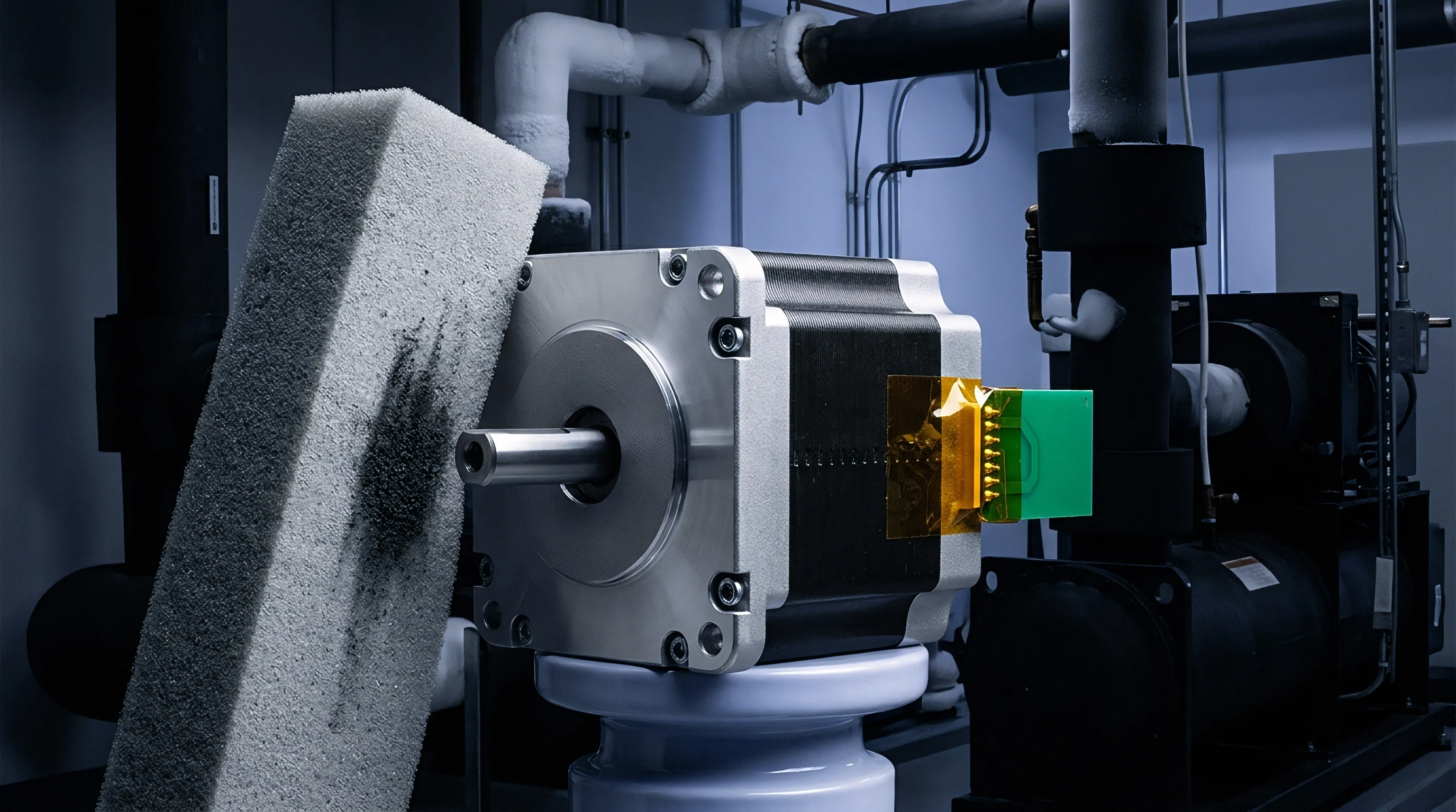
Barrier
Interfacial pads provide mechanical pressure regulation alongside thermal boundary management. The microcellular geometry inherently introduces thermal insulation between adjacent cells. During routine charge and discharge, this insulation restricts heat flow, driving thermal management through cell bottoms into cold plates.
During thermal runaway, this low thermal conductivity acts as a critical fire barrier, delaying or preventing adjacent cell propagation.
Thermal conductivity values below 0.08 W/m·K force heat dissipation downward toward liquid-cooled baseplates.
Cell failure tests expose interfacial foams to severe convective and radiative thermal loads. When a single cell undergoes catastrophic thermal runaway, surface temperatures exceed 700 degrees Celsius within seconds, accompanied by high-velocity gas venting and flaming particulates. The interfacial pad must resist burn-through to prevent cascading failure into neighboring cells.
Standard polyurethane foams depolymerize and decompose rapidly above 250 degrees Celsius, releasing volatile flammable hydrocarbons that accelerate fire spread. High-performance battery modules incorporate flame-retardant silicone sponges, inorganic aerogel blankets, or ceramic-fiber composites to withstand thermal shock.
Flame retardancy requires third-party certification under UL 94 standards for flammability of plastic materials. A horizontal burn rating like HBF proves insufficient for commercial battery pack safety cases. Transport and vehicle regulations demand vertical burn ratings of UL 94 V-0, where test specimens self-extinguish within 10 seconds of flame removal without dropping burning particles.
Achieving a V-0 classification in low-density elastomeric foams requires heavy loadings of halogen-free fire retardants, such as aluminum trihydrate, magnesium hydroxide, or intumescent phosphorus compounds. These mineral fillers increase foam density and raise the compressive modulus, narrowing the mechanical compliance window.
Ceramic-forming silicone elastomers resolve the tradeoff between mechanical compliance and thermal survivability. These hybrid formulations behave as standard flexible foams during normal operating conditions. When exposed to flame temperatures above 600 degrees Celsius, the siloxane polymer backbone oxidizes into a coherent, mechanically rigid silicon dioxide ceramic shield.
This pyrolyzed mineral crust maintains dimensional spacing between cell cans, insulating the adjacent cell against conductive heat transfer throughout the thermal event.
Dielectric isolation prevents high-voltage electrical arcing across cell casings during both cyclic operation and physical impact. Prismatic cell cans are typically fabricated from thin deep-drawn aluminum, insulated with a wrapped layer of polyethylene terephthalate film measuring 50 to 100 micrometers in thickness. Normal vehicle vibrations, combined with interfacial shearing forces caused by cell breathing, can abrade this thin exterior film over time.
The interfacial pad serves as a secondary dielectric barrier. Elastomeric pads specified for electric vehicle modules demonstrate dielectric breakdown strengths exceeding 15 kV/mm per ASTM D149, preventing isolation faults if the primary PET wrap fails.
Testing according to UL 2580 reveals that thermal barrier degradation directly invalidates module propagation containment claims.


Sizing
Determining interfacial pad thickness and modulus requires a balance between beginning-of-life assembly limits and end-of-life swelling envelopes. Module designers execute analytical tolerance stack-up calculations combined with non-linear finite element analysis to define the mechanical window. The interfacial pad must compress sufficiently to accommodate manufacturing tolerances and operational cell expansion without exerting crushing forces on cell jelly rolls.

Mechanical Sizing Workflow
- Envelope definition establishes the total internal distance between structural module end-plates, dividing this space among cell nominal dimensions, cold plate interfaces, and compression gaps.
- Tolerance stack-up calculates the statistical worst-case dimensional variance, incorporating cell thickness tolerances of plus or minus 0.3 mm alongside pad manufacturing thickness tolerances.
- Swelling quantification applies electrochemical dilation metrics, integrating reversible state-of-charge breathing with irreversible capacity-loss expansion across the target cycle lifespan.
- Modulus matching plots total anticipated compression against candidate foam compression force deflection curves to verify that minimum and maximum boundary pressures remain between 0.05 MPa and 0.80 MPa.
- Thermal validation verifies that pad mechanical properties survive specified continuous and peak environmental temperatures without transitioning into densification or extreme relaxation regimes.
Silicon-graphite composite anodes demonstrate non-linear swelling behavior over their cycling lifespan. Graphite expansion scales proportionally with state of charge, contracting during discharge. Silicon particles undergo substantial irreversible particle pulverization and continuous solid electrolyte interphase reconstruction, driving permanent volumetric dilation.
A prismatic cell with a 3 percent silicon content expands roughly 1.5 percent reversibly between 0 percent and 100 percent state of charge, but accumulates up to 8 percent permanent thickness growth after 1,500 full equivalent cycles.
| Operating Condition | Cell State | Nominal Pad Strain (%) | Target Counter-Pressure (MPa) | Mechanical Failure Risk |
|---|---|---|---|---|
| Fresh Module Assembly | 0% SOC, Fresh | 15 to 25 | 0.03 to 0.08 | Under-compression, cell vibration looseness |
| Beginning of Life High Charge | 100% SOC, Fresh | 30 to 40 | 0.10 to 0.20 | Within optimum electrochemical contact window |
| Mid-Life Cyclic Operation | 50% SOC, 500 Cycles | 35 to 45 | 0.15 to 0.30 | Within optimum electrochemical contact window |
| End of Life High Charge | 100% SOC, 1500 Cycles | 50 to 60 | 0.50 to 0.90 | Approaching foam densification threshold |
| End of Life Extreme Degradation | 100% SOC, Over-cycled | > 65 | > 1.50 | Separator pore closure, end-plate weld fracture |
Module mechanical packaging dictates physical foam retention during high-speed automated assembly. Interfacial pads incorporate pressure-sensitive adhesive backings applied to one or both surfaces. Acrylic transfer tapes chosen for module fabrication must withstand long-term exposure to trace electrolyte vapors and volatile organic outgassing without decomposing.
Single-sided adhesive configurations permit dry cell-to-pad interfaces on one face, facilitating thermal expansion slip without inducing high shear stresses in cell aluminum jackets. Adhesives must maintain thermal stability from -40 degrees Celsius to 85 degrees Celsius to prevent adhesive migration into module electrical connections.
A typical module stack contains twelve 100 Ah prismatic cells arranged in series. Nominal cell thickness measures 45.0 mm with an incoming manufacturing tolerance of plus or minus 0.4 mm. A pad thickness of 2.0 mm provides 1.5 mm of working compliance across cell interfaces, absorbing stack-up errors while buffering dynamic breathing.
The total module dimension relies on the summation of these elastomeric components.
An engineer balancing these mechanical dimensions encounters an operational limit: does increasing pad thickness to suppress end-of-life pressure compromise total volumetric energy density?

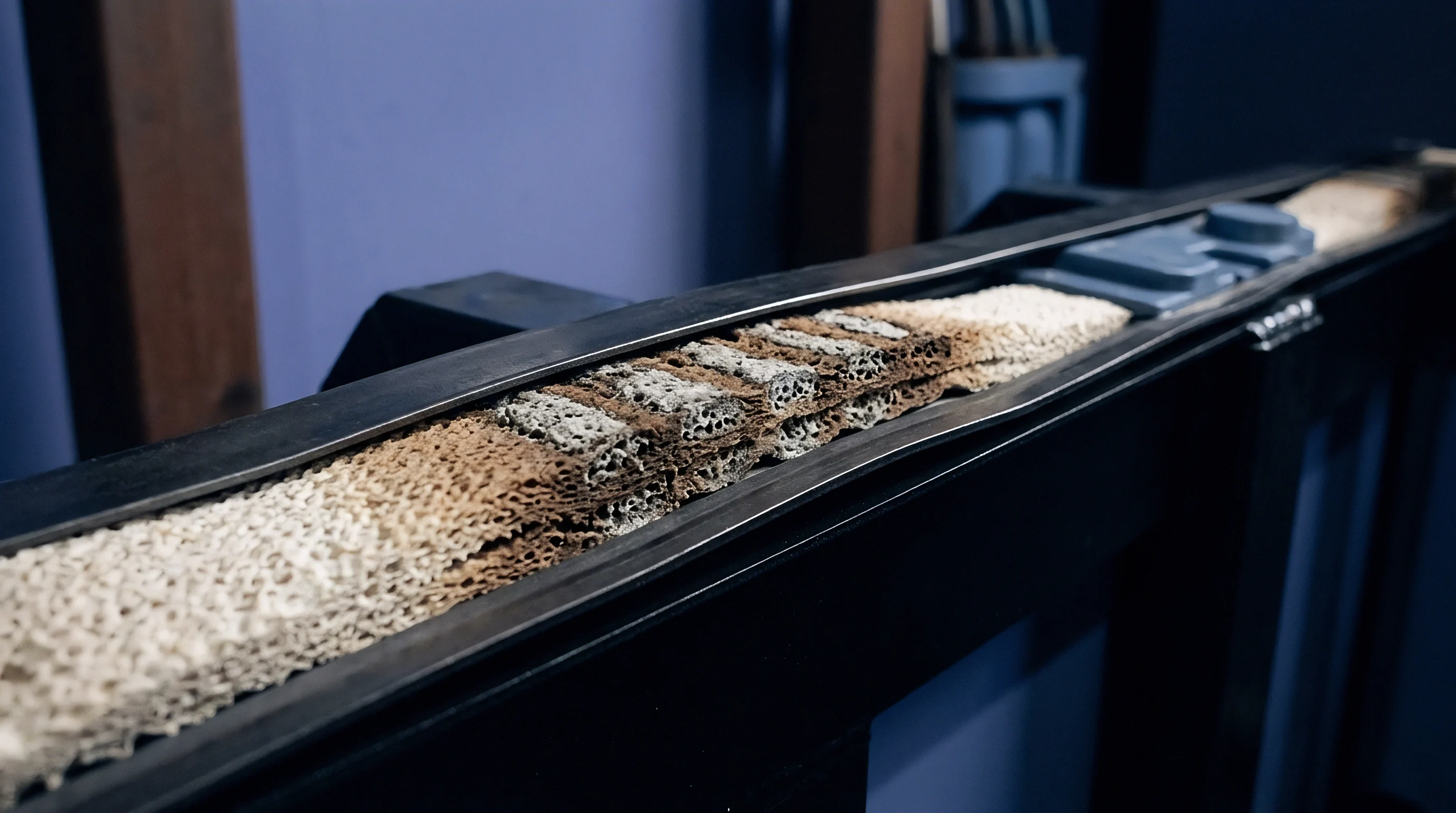
Carriage
Transporting lithium-ion cells and assembled modules demands strict compliance with international dangerous goods frameworks. Interfacial compression pads influence safety testing outcomes governed by the UN Manual of Tests and Criteria, Part III, subsection 38.3. Packaging approvals, carrier clearances, and import entries require verified test summaries demonstrating structural survivability across defined vibration, shock, and thermal environments.

Regulatory Demands under UN 38.3 Testing
Mechanical vibration profiles defined under UN 38.3 Test T.4 apply severe harmonic sinusoidal sweeps from 7 Hz to 200 Hz across three mutually perpendicular axes. If interfacial compression pads lack sufficient preload counter-force, individual prismatic cells experience internal harmonic resonance, causing physical motion within the module housing. This relative movement abrades terminal busbar welds, stresses flexible circuit boards, and wears through cell can exterior PET wraps.
Achieving compliance requires interfacial pads to exert adequate static pressure to frictionally lock cells in place throughout the 3-hour per axis test sequence.
UN 38.3 Test T.5 executes mechanical shock testing via half-sine shock pulses of 150 g peak acceleration with an 11 millisecond duration for small modules, or 50 g peak acceleration with an 11 millisecond duration for large battery assemblies. Under these inertial loads, interfacial foams act as energy-absorbing dampeners. A pad with inadequate compressive strength bottoms out instantly, transferring peak impact loads directly into adjacent cell casing walls, causing denting, internal electrode misalignment, or seal leakage.
Cells exhibiting voltage drops, electrolyte leakage, or mechanical ruptures during Test T.5 fail transport certification automatically.
UN 38.3 Test T.2 requires battery assemblies to survive thermal cycling between -40 and 72 degrees Celsius without mechanical failure.
Dangerous goods transport regulations mandate specific handling and documentation pathways:
- Packing Instruction 965 governs standalone lithium-ion cells and modules transported via cargo aircraft, limiting state of charge to 30 percent and requiring certified packaging.
- UN Test Summaries require clear disclosure of mechanical test completion, identifying the specific module architecture and interfacial pad integration status.
- Competent Authority Approvals govern prototype transport for battery packs undergoing development before complete UN 38.3 type-testing certification.
- Special Provision 376 regulates damaged or defective cells, imposing rigid non-propagation packaging containing non-combustible, thermally insulating cushioning materials.
Thermal shock conditions in UN 38.3 Test T.2 repeatedly cycle modules between -40 degrees Celsius and 72 degrees Celsius with maximum 30-minute transition times, holding plateau temperatures for at least 4 hours across 10 cycles. This severe thermal variation stresses the differential thermal expansion boundaries between aluminum cells, steel tie rods, and polymeric compression pads. If an interfacial foam shrinks or embrittles at low temperatures, module internal clamp force vanishes.
When the module returns to 72 degrees Celsius, elevated internal cell pressures combined with thermally softened foam can lead to uncontrolled can expansion.
Carriers reject lithium-ion module consignments when the accompanying UN 38.3 test summary omits structural revisions or fails to match the shipped mechanical bill of materials.


Audit
Bridging the gap between engineering specifications and shipped components requires rigorous incoming inspection and supplier quality controls. Factory-floor audits must verify that delivered foam batches match the mechanical, thermal, and flammability parameters established during initial module design qualification. Relying exclusively on supplier certificates of analysis invites significant operational and commercial exposure.

Incoming Inspection Protocols and Factory Audits
Incoming quality gates evaluate dimensional consistency and density on raw foam rolls or die-cut parts. Pad thickness variations directly distort the module’s mechanical tolerance stack-up. A thickness deviation of plus 0.25 mm across a 16-cell module stack introduces 4.0 mm of unintended mechanical displacement into end-plates, elevating beginning-of-life assembly pressures past 0.35 MPa.
Thickness verification requires continuous non-contact optical micrometers or dead-weight mechanical dial indicators conforming to ASTM D3574 Test A, applying a precisely regulated foot pressure of 140 Pa to avoid compressing the porous foam during measurement.
Density checks uncover processing defects such as improper gas blowing, microcellular collapse, or uneven filler dispersal. An operator cuts standardized 100 mm by 100 mm die specimens and evaluates mass via calibrated analytical balances to ensure density stays within plus or minus 5 percent of the master drawing specification. Significant variations in bulk density correlate directly with shifts in compression force deflection curves and thermal conductivity, signaling unstable chemical dosing on the supplier’s continuous casting line.
Lot-level compression force deflection testing acts as the ultimate mechanical gate. Automated tensile and compression testing frames compress incoming foam specimens to 25 percent and 50 percent strain at a displacement rate of 50 mm/minute, logging the resultant force profile. If the measured 25 percent CFD value deviates by more than 15 percent from the qualified baseline curve, the entire raw material lot faces quarantine.
Using an out-of-spec stiff foam crushes cell internals, while an overly soft foam allows dynamic vibration during transport.
Supplier manufacturing facility audits focus heavily on chemical cure cycles, blowing agent controls, and converted edge quality. Inspecting conversion facilities reveals die-cutting defects such as edge chamfering, roll crush, and burred edges caused by dull steel rule dies. These localized geometric defects create non-uniform stress points against fragile cell walls.
Production audits confirm that adhesive lamination processes operate under tightly regulated tension to prevent stretching the elastomeric foam prior to die cutting, which leads to unpredictable post-cut shrinkage in assembly warehouses.
Under international commercial law, when delivered elastomeric pads cause pack assembly failures or trigger field recalls, the importer of record bears primary liability unless incoming inspection records definitively prove manufacturing non-conformance.

Arithmetic
Balancing interfacial foam performance against landed pack cost reveals significant trade-offs across material chemistries. A microcellular polyurethane pad costs between 0.80 and 1.50 USD per cell interface, while an equivalent cross-linked silicone sponge ranges from 2.50 to 4.20 USD. Aerogel composite blankets carrying ceramic insulation exceed 6.00 USD per interface.
In a commercial passenger vehicle battery pack containing 192 prismatic cells, interfacial compression materials account for 150 to over 1,150 USD in direct bill-of-materials costs.
The landed cost calculation incorporates freight, tariffs, secondary conversion, and processing scrap:
- Master roll logistics carry substantial volumetric freight penalties because low-density elastomeric materials occupy container volume long before reaching maximum shipping weight limits.
- Rotary die conversion generates 15 percent to 30 percent edge trim and web skeleton scrap, which converters factor directly into finished unit pricing.
- Adhesive lamination costs add 0.30 to 0.70 USD per square meter for high-performance automotive-grade acrylic transfer films.
- Scrap allowance margins add 2 percent to 4 percent to order volumes to offset assembly floor application errors and handling damage.
Selecting an inadequate material to minimize bill-of-materials cost introduces severe downstream financial exposure. If a low-cost polyurethane foam undergoes excessive stress relaxation, cells degrade prematurely from delamination, forcing warranty replacements at hundreds of dollars per pack. Conversely, excessive compression set leading to mechanical loosening under road vibration can spark internal short circuits, triggering catastrophic pack burn-out and massive global vehicle safety recalls.
A rigorous sourcing framework balances raw material expense against long-term operational and safety reliability across the full lifecycle of the battery system.
Whether accelerated long-term aging tests accurately capture the true mechanical relaxation behavior of siloxane cross-links under dynamic mechanical swelling remains open to ongoing industry dispute.