Quantifying Impeding Voltage Relaxation Signatures to Prevent Sub-Zero Lithium Plating in Cold Stores
Post-charge voltage relaxation inflection tracking reveals sub-zero metallic lithium plating before irreversible dendrite growth damages cold storage battery packs.


Cold
Sub-zero distribution facilities operating automated guided vehicles and electric forklifts at minus twenty degrees Celsius expose lithium-ion cells to aggressive electrochemical stress. Recharging packs inside frozen storage halls alters the thermodynamics of the graphite anode. Liquid electrolyte viscosity increases by two orders of magnitude between room temperature and sub-zero thresholds, restricting lithium ion diffusion through the porous separator and within the solid electrode matrix.
When charging current flows into a cell under these thermal constraints, the electrical energy forces lithium ions toward the negative electrode faster than they can diffuse into the graphite host structure.
Energy storage systems designed for refrigerated logistics frequently run continuous high-rate fast-charge cycles during short break periods to maintain fleet operational uptime. Standard battery management electronics monitor bulk pack voltage, total current, and surface temperature sensors, but standard voltage thresholds fail to capture local kinetic bottlenecks at the graphite surface. Lithium ion movement slows as temperature drops, causing the negative electrode potential to plunge beneath zero volts relative to the metallic lithium reference couple.
Metallic lithium then begins to deposit directly onto the graphite surface instead of intercalating between the graphene sheets.
Deposition occurs quietly during high state-of-charge sub-zero fast charging, converting active lithium ions into solid metallic dendrites. Initial metallic lithium deposits remain highly reactive with the surrounding organic liquid electrolyte. This secondary reaction permanently consumes active material and forms a thick, irregular solid electrolyte interphase layer on the plated metal surface.
Over successive cold storage operational shifts, dendrites propagate across the separator, increasing internal cell resistance, accelerating permanent capacity loss, and elevating short-circuit risks during subsequent pack warming cycles.
Plating initiates whenever the local graphite potential drops below zero volts against the metallic lithium reference couple during charge.

Thermodynamic and Kinetic Thresholds
Low-temperature charge acceptance depends on the competition between two distinct reaction paths at the anode interface. Intercalation carries a distinct activation energy barrier that rises dramatically as temperature drops, whereas the metallic lithium reduction reaction exhibits a flatter kinetic temperature dependence. Charge current applied at minus fifteen degrees Celsius drives the graphite overpotential negative within seconds if the applied C-rate exceeds the solid-state diffusion capability of the carbon particles.
Standard graphite anodes operating at room temperature accept charging current up to two C without surface deposition, yet the exact same chemistry under cold storage conditions initiates metallic plating at C-rates as low as 0.05 C.
Cell design choices modify these kinetic thresholds. Thin electrode coatings, high-porosity separators, and specialized low-viscosity electrolyte blends incorporating low-melting-point co-solvents like ethyl acetate or fluoroethylene carbonate extend the non-plating operating envelope. However, commercial cold storage fleets predominantly run standardized high-energy-density graphite cells containing standard carbonate formulations due to landed cost constraints.
Sourcing managers specifying packs for zero-degree and sub-zero duty must identify the precise boundary where kinetic limitations transition from high charge transfer resistance into active metallic deposition.
Operational safety limits derived at twenty-five degrees Celsius provide zero protection against cold storage failure modes. Standard commercial battery pack warranties disclaim coverage when degradation stems from sub-zero charge execution, placing the full financial exposure of premature fleet replacement on the fleet operator. Detecting the inception of metallic plating before dendrites breach the separator requires continuous tracking of subtle electrochemical signals emitted immediately after charge current turns off.


Kinetics
Electrochemical behavior during sub-zero charging reflects a severe imbalance between charge transfer rates and bulk transport dynamics within the electrolyte phase. Solid-state diffusion coefficients for lithium inside graphite particles drop from roughly 10 raised to the power of minus nine square centimeters per second at room temperature down to 10 raised to the power of minus eleven or minus twelve at minus twenty degrees Celsius. Desolvation of the lithium ion from its surrounding organic solvent sheath creates an additional kinetic bottleneck at the interphase.
The energy required to strip solvent molecules before entering the graphite lattice dominates total cell impedance at low temperatures.
When charging current ceases, the cell does not instantly drop to its true open-circuit voltage. Voltage drops rapidly through an initial ohmic phase, followed by a slower relaxation curve governed by concentration gradient dissipation and charge transfer equilibration. If solid metallic lithium formed on the anode during charge, a secondary electrochemical process overlays this standard relaxation curve: the plated metallic lithium begins to re-intercalate spontaneously into the adjacent graphite matrix or react corrosively with the electrolyte solvent.

Electrochemical Competition Mechanics
Two simultaneous processes govern the post-charge phase when metallic lithium exists on the anode surface:
- Chemical Reintercalation drives metallic lithium to give up electrons to the graphite structure, dissolving back into lithium ions that intercalate into vacant host sites while equalizing local potential differences.
- Corrosive SEI Formation consumes metallic lithium through irreversible chemical oxidation with the electrolyte solution, building resistive interphase compounds and generating trace gaseous byproducts.
- Concentration Gradient Dissipation redistributes intercalated lithium ions evenly throughout the bulk volume of individual graphite particles over extended rest periods.
- Electrolyte Salt Redistribution neutralizes concentration polarization across the porous electrode thickness and separator matrix until ionic equilibrium settles.
The chemical re-intercalation of metallic lithium acts as an internal self-discharge mechanism localized at the anode surface. Because metallic lithium holds a fixed thermodynamic potential of exactly zero volts against the lithium couple, the presence of surface plating pins the negative electrode potential close to zero volts for as long as metallic lithium remains present. This pinning effect alters the total cell terminal voltage decay signature during the initial minutes or hours of post-charge rest.
Cell manufacturers frequently claim that proprietary electrolyte additives completely suppress low-temperature plating without providing the underlying differential voltage relaxation evidence to substantiate the assertion. Internal testing under controlled cold chamber conditions reveals that while specialized co-solvents reduce charge transfer impedance, they merely delay the onset threshold rather than eliminating the physical thermodynamic driving force. Relying entirely on supplier marketing datasheets leaves industrial cold storage fleets vulnerable to unmodeled cell atrophy.

Signature
Tracking post-charge open-circuit voltage decay yields clear diagnostic markers capable of separating pure concentration polarization from metallic lithium stripping and re-intercalation. In a cell free of metallic plating, post-charge voltage relaxation follows a smooth, monotonic decay curve that mirrors mass diffusion kinetics, decaying logarithmically over time. When surface plating occurs, the voltage relaxation profile exhibits a distinct plateau or inflection point caused by the thermodynamic potential pinning of the metallic lithium film on the anode.
Mathematical extraction of this signature relies on taking the time derivative of the relaxation voltage curve, expressed as dV/dt, or plotting differential relaxation voltage against elapsed rest time. Plotting dV/dt against relaxation time transforms subtle voltage plateaus into sharp, quantifiable peak signatures. The magnitude, time location, and area under this differential peak correlate directly with the mass of metallic lithium deposited on the negative electrode surface.
Taking the time derivative of post-charge relaxation voltage reveals hidden plateaus that prove metallic lithium deposition occurred on the anode surface.

Differential Relaxation Metrics
Quantifying the relaxation signature requires calculating three primary mathematical metrics immediately following charge termination:
- Calculate the baseline diffusion decay constant by fitting the logarithmic voltage slope during the final stage of relaxation after all metallic lithium has fully re-intercalated or dissolved.
- Identify the inflection time point where the derivative curve dV/dt reaches a local minimum or local maximum, marking the transition between metallic lithium dissolution and pure solid-state diffusion.
- Integrate the area under the differential voltage relaxation peak above the baseline diffusion curve to estimate total plated lithium mass expressed in units of milliamperes-hour.
Differential relaxation curves vary significantly across operating temperatures and initial states of charge. Lower temperatures extend the relaxation decay time, shifting the derivative peak further to the right along the time axis. Higher states of charge increase the thermodynamic driving force for lithium intercalation, altering the amplitude of the relaxation signature.
The diagnostic window remains open only for a limited period following charge termination. Once all metallic lithium chemically re-intercalates into the graphite or reacts with electrolyte, the cell voltage signature drops back to the standard diffusion decay profile. A battery management system that fails to sample post-charge voltage at adequate frequency during the initial twenty minutes misses the critical window entirely, rendering the signature invisible to remote diagnostic telemetry.

Can Differential Relaxation Curves Reliably Disambiguate Plating from Diffusion Overpotential?
Distinguishing between high concentration overpotential and physical metallic plating requires rigorous mathematical analysis of the second derivative, d2V/dt2. Pure diffusion decay exhibits a strictly positive second derivative during the entire post-charge relaxation period. Metallic lithium stripping creates a clear sign change in the second derivative, transitioning from negative to positive as the metallic phase dissipates.
This mathematical transition provides an absolute, non-subjective binary metric that embedded firmware algorithms can compute in real time without heavy computational load.
Noise in raw voltage measurements introduces challenges when calculating higher-order derivatives in field applications. Standard BMS voltage sampling channels with lower resolution or high electrical noise floor obscure the inflection signature. Smoothing raw voltage streams using moving-average filters or Savitzky-Golay polynomial filters restores signature clarity, permitting robust peak extraction under real-world cold store operational conditions.
Whether embedded microcontroller hardware can perform polynomial smoothing and derivative calculation fast enough across sixty individual cell channels without causing telemetry delays remains an open engineering question for hardware architects.


Diagnostic
Integrating relaxation analysis into operational cold storage battery packs requires a disciplined software architecture inside the battery management controller. The BMS firmware must execute a dedicated diagnostic routine whenever charge current drops to zero. Operating cold storage fleets cannot afford offline laboratory equipment for routine health tracking, making on-board differential relaxation analysis the primary defense against catastrophic dendrite accumulation.
Hardware requirements for on-board relaxation tracking are strict. Voltage measurement channels must deliver at least sixteen bits of analog-to-digital resolution with a absolute accuracy better than one millivolt per cell across the entire operating temperature band from minus thirty to plus forty degrees Celsius. Sampling rates during the initial five minutes of rest must maintain a minimum threshold of two samples per second to capture fast transient voltage shifts without signal aliasing.
Standard battery management systems that monitor only gross pack voltage and surface temperature fail to detect localized lithium plating until cell capacity drops permanently.

Embedded Firmware Implementation
Implementing relaxation diagnostics in embedded software involves systematic data handling steps within the battery management microchip:
- Current Threshold Detection triggers raw voltage array recording as soon as pack charge current drops below fifty milliamperes for three consecutive sampling intervals.
- Temperature-Compensated Calibration applies temperature-specific gain offset corrections to raw ADC voltage streams to prevent thermal drift from faking derivative signatures.
- Array Signal Filtering passes time-series voltage buffers through a low-pass digital filter to suppress electrical switching noise generated by auxiliary cold store systems.
- Derivative Peak Evaluation computes first and second discrete differences across the voltage buffer to check for sign changes indicating metallic phase dissolution.
- Flag Generation And Response sets an internal diagnostic warning code and adjusts future charge current limits downward if the derivative peak area exceeds pre-set safety thresholds.
Automated adjustment of charging parameters following a detected plating event protects pack health over extended operating lifespans. When the firmware flags a valid relaxation signature, the controller dynamically reduces maximum allowed low-temperature charging current by twenty to forty percent for subsequent charge events. This adaptive feedback loop restricts plating growth, trading small amounts of charge speed for sustained operational longevity.
Ignoring voltage relaxation signatures during cold store fleet operations results in severe commercial consequences. Lithium dendrites accumulating undetected across hundreds of operational cycles eventually pierce the polymer separator film. When a cell with compromised separators undergoes routine ambient warming during maintenance or transport, internal micro-short circuits trigger rapid thermal runaway, destroying the complete pack and risking major cold store facility fire damage.

Bench
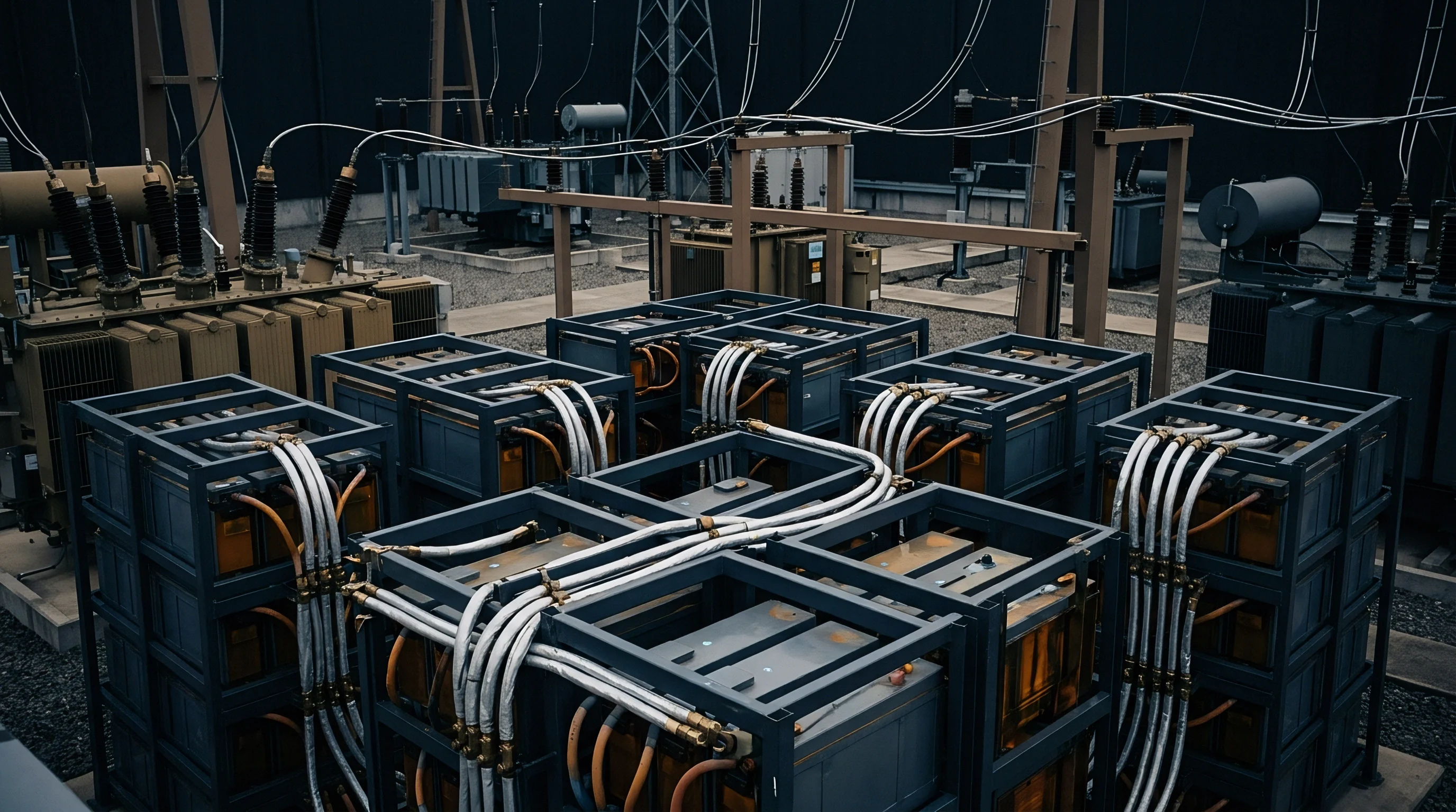
Validating voltage relaxation signature detection algorithms requires controlled laboratory testing using specialized environmental test chambers and high-precision battery cyclers. Test channels must feature four-wire Kelvin sensing leads connected directly to cell terminals to eliminate contact resistance errors during high-current pulse transitions. Thermal chambers must hold ambient temperature stable within plus or minus 0.2 degrees Celsius across multi-day testing protocols.
Constructing a reference signature library involves testing fresh cell samples across systematic temperature increments, state-of-charge steps, and C-rates. By systematically driving cells past their kinetic plating limits while logging millivolt-level relaxation curves, laboratory technicians establish the baseline derivative thresholds used to configure embedded BMS software alert triggers.

Worked Derivative Calculation Example
Evaluating an actual relaxation data sequence illustrates the mathematical procedure executed by test channel processing software. Consider a 100Ah prismatic graphite/NMC cell charged at 0.5C at minus fifteen degrees Celsius up to eighty percent state of charge, followed by an immediate thirty-minute open-circuit rest period.
The cycler records cell terminal voltage at 1.0-second intervals following charge current shutoff. Table entries below trace a twenty-second window around the inflection point where metallic lithium re-intercalation completes.