Solid Electrolyte Interphase Dynamic Impedance Evolution under Extended Sub Zero Cycling Regimes
Extended sub-zero cycling drives exponential SEI impedance growth via lithium plating and film cracking, requiring low-desolvation additives to prevent roll-off.

Chill
Sub-zero operating environments severely constrain lithium-ion battery chemistry. As ambient temperatures fall from room-temperature baselines down to minus twenty or minus forty degrees Celsius, liquid electrolyte viscosity climbs sharply while bulk ionic conductivity drops by more than an order of magnitude. Lithium ions move through the liquid phase against heightened resistance, but the primary transport bottleneck occurs at the electrode interface.
Before intercalating into the host graphite lattice, an ion must shed its solvation sheath of cyclic and linear carbonate molecules.
The activation energy required for lithium desolvation ranges between 50 and 70 kilojoules per mole depending on solvent chemistry. At sub-zero temperatures, this energetic barrier creates substantial overpotential during charge cycles. The solid electrolyte interphase ~ an organic-inorganic composite layer formed during initial factory formation ~ controls ionic flux into the anode.
Under low thermal conditions, ionic transport through this film slows down, driving up baseline cell polarization.
Continuous sub-zero cycling under high charge rates amplifies internal potential gradients across the passivating surface film. Localized potential drops at the graphite anode push the working potential below zero volts against the lithium reference couple. Under these conditions, the passivating interface undergoes simultaneous structural and chemical changes.
Secondary decomposition reactions convert soluble organic species into dense inorganic precipitates, permanently altering layer thickness and chemical stoichiometry.
Early impedance spikes at sub-zero operating temperatures stem either from transient electrolyte sluggishness or from permanent interface thickening.
Spectroscopy
Electrochemical impedance evaluation tracks internal cell resistance changes across temperature steps. At room temperature, standard Nyquist plots for commercial lithium-ion cells display a high-frequency bulk electrolyte intercept alongside two overlapping semicircles that represent passivating film resistance and interfacial charge transfer resistance. Lowering the measurement temperature to minus twenty degrees Celsius resolves these overlapping transport features into discrete spectral arcs, making it possible to isolate distinct degradation pathways.
Resolving High-Frequency Interfacial Arc
Kilohertz-frequency measurements capture bulk electrolyte conductivity shifts as liquid solvents cool. The high-frequency real-axis intercept, designated as bulk ohmic resistance, expands linearly with temperature drops due to solvent molecular friction. The first spectral semicircle at high-to-mid frequencies corresponds directly to ion migration through the solid electrolyte interphase; under extended low-temperature cycling, its diameter expands steadily over hundreds of cycles.
The expansion of the passivation arc reflects physical layer growth and chemical phase transformation. Inorganic species such as lithium fluoride and lithium carbonate accumulate within the layer matrix, increasing resistance to lithium ion diffusion.
At minus twenty degrees Celsius, charge transfer resistance expands by a factor of eighteen compared to room temperature baselines after two hundred cycles.
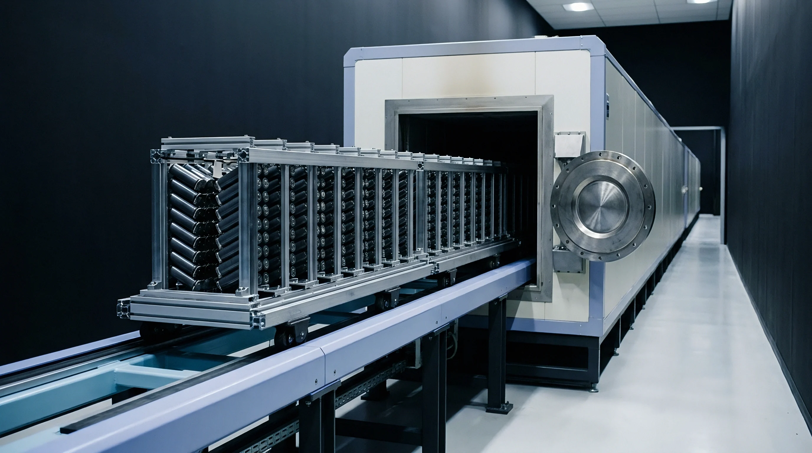
Dynamic Shift in Charge Transfer Resistance
Low operating temperatures expand the mid-frequency semicircles on complex plane impedance plots. This mid-frequency arc quantifies charge transfer resistance across the electrode interface, representing the kinetic barrier of ion desolvation and electron exchange. As low-temperature cycling continues, charge transfer resistance grows four to six times faster than bulk electrolyte resistance, dominating the total cell voltage drop during cold discharge.
| Temperature (°C) | Cycle Count | Ohmic Resistance R_omega (mΩ) | Passivation Resistance R_sei (mΩ) | Charge Transfer Resistance R_ct (mΩ) |
|---|---|---|---|---|
| 25 | 0 | 0.82 | 0.45 | 0.61 |
| -10 | 100 | 1.95 | 1.12 | 2.84 |
| -20 | 200 | 3.41 | 2.88 | 11.35 |
| -30 | 300 | 5.82 | 5.40 | 28.90 |
| -40 | 500 | 11.20 | 12.75 | 74.10 |
| Data recorded at 50% state of charge using a 10 mV sinusoidal excitation amplitude from 100 kHz to 10 mHz. | ||||
Low-frequency Warburg tails on the Nyquist spectrum map solid-state lithium diffusion within the graphite active particles. At sub-zero temperatures, solid-state diffusion coefficients drop by two orders of magnitude, shifting the Warburg slope upward into the mid-frequency charge transfer arc. Disentangling these overlapping contributions requires a multi-temperature distribution of relaxation times analysis to isolate discrete time constants tied to specific kinetic processes.
Mid-frequency arc growth under sub-zero cycling stems either primarily from inorganic film densification or from continuous organic decomposition at newly exposed graphite facets.

Morphology
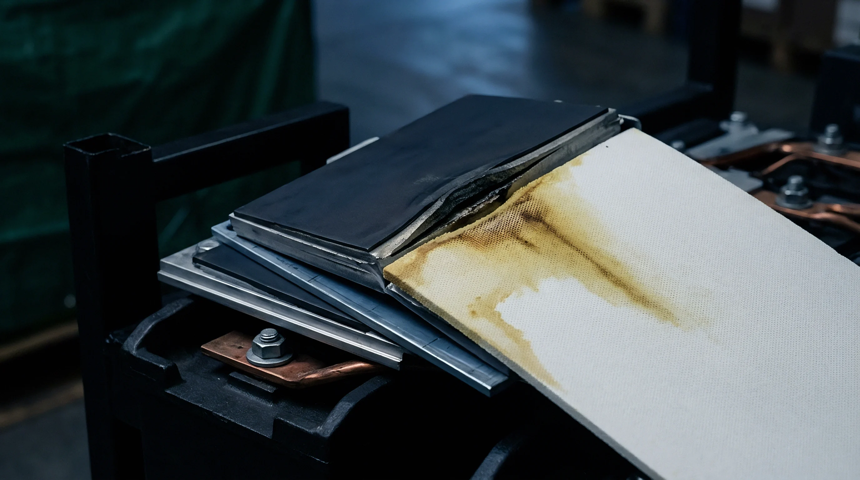
Microstructural evolution at the anode surface governs long-term capacity retention during cold-climate operation. As solid electrolyte interphase films grow non-uniformly under low-temperature stress, the layer loses mechanical integrity. This interplay between chemical precipitation and mechanical stress creates a self-reinforcing degradation loop during continuous sub-zero operation.
What Drives Interfacial Passivation Decay below Freezing?
Continuous sub-zero cycling forces localized potential drops at active graphite sites during charging. High charge rates at low temperatures push the local graphite working potential negative relative to metallic lithium deposition. As solid films thicken during extended cycling, metallic lithium precipitates directly onto the anode surface rather than intercalating cleanly into the host crystal lattice.
Deposited metallic lithium reacts aggressively with surrounding organic liquid electrolytes. Freshly plated lithium consumes solvent and salt species, generating secondary passivating compounds. This parasitic side reaction permanently traps active lithium ions, driving rapid capacity loss across consecutive cold cycles.
- Metallic Lithium Plating ~ Metallic lithium deposits on active graphite sites when charge overpotential forces the local surface potential below zero volts against the lithium reference.
- Brittle Film Micro-Fracturing ~ Thermal stress and volumetric changes crack the rigid inorganic passivating layer during sub-zero current pulses.
- Active Solvated Species Depletion ~ Continuous decomposition of organic carbonates at freshly exposed anode interfaces depletes liquid electrolyte volume and alters salt concentration.
- Dendritic Accumulation ~ Localized high current densities accelerate non-uniform metallic lithium growth, heightening short-circuit risks inside the cell core.

Structural Breakdown of Passivating Layers
Mechanical stress during rapid lithium insertion fractures brittle inorganic salt deposits on active anode surfaces. The solid electrolyte interphase is not static; volume changes in the underlying host material generate micro-cracks across the layer. At room temperature, flexible organic polymeric components accommodate modest expansion, but at minus twenty degrees Celsius, these polymers lose elasticity and turn the film into a brittle matrix prone to rupture.
Repeated plating and stripping cycles during cold charging transform compact passivating structures into porous resistive layers.
Fracturing exposes fresh graphite facets to liquid electrolyte. Freshly exposed carbon surfaces undergo immediate chemical reduction, consuming solvent species to rebuild passivating films. Repeated cracking and reforming cycles thicken the interphase layer from a typical room-temperature thickness of 20 nanometers to over 150 nanometers after extended sub-zero cycling.
This thickened, porous layer traps electrolyte pockets, increases tortuosity for incoming lithium ions, and elevates overall cell polarization.
Ignoring microstructural film fracturing during continuous cold operation leads directly to rapid capacity roll-off, elevated thermal runaway risks during fast recharges, and field warranty failures for cold-climate battery packs.
Formulation
Electrolyte engineering alters interfacial film composition and improves low-temperature transport kinetics. Standard electrolyte formulations tailored for high-temperature stability perform poorly under extended freezing conditions, imposing steep polarization penalties. Modifying liquid solvent mixtures and film-forming additives lowers bulk viscosity while reducing interfacial desolvation barriers.
Electrolyte Co-Solvent Engineering
Standard linear carbonate solvents exhibit high melting points and elevated viscosity below zero degrees Celsius. Ethylene carbonate provides the high dielectric permittivity needed to dissolve lithium salts, but its melting point of 36 degrees Celsius limits low-temperature fluidity. Blending low-viscosity carboxylate ester co-solvents such as ethyl acetate, methyl propionate, or ethyl propionate reduces liquid viscosity at sub-zero temperatures.
Incorporating ester co-solvents increases low-temperature ionic conductivity beyond 2 millisiemens per centimeter at minus thirty degrees Celsius. Consider a 100 Ah industrial lithium iron phosphate cell cycling continuously at minus thirty degrees Celsius under a 0.5C charge regime with a baseline electrolyte of 1.0 M LiPF6 in equal volumes of ethylene carbonate and dimethyl carbonate. Anode potential drops below zero volts within twelve minutes of charge initiation, triggering severe lithium plating and an impedance increase of 4.2 mΩ per one hundred cycles.
Replacing fifty percent of the dimethyl carbonate with ethyl acetate lowers electrolyte viscosity from 2.4 centipoise to 0.8 centipoise at minus thirty degrees, boosting ionic conductivity from 0.4 mS/cm to 2.1 mS/cm. Adding two percent fluoroethylene carbonate constructs a fluorinated interface rich in lithium fluoride, suppressing metallic lithium dendrite formation and cutting impedance growth to 0.9 mΩ per one hundred cycles under identical thermal loads.
| Solvent Blend | Additive System (wt%) | Conductance at -30°C (mS/cm) | Interfacial Growth Rate (mΩ/100 cycles) | Retained Capacity at 500 Cycles (%) |
|---|---|---|---|---|
| EC/DMC (1:1) | None | 0.41 | 4.20 | 54.2 |
| EC/EMC/DMC (1:1:1) | 2% VC | 0.85 | 2.80 | 68.5 |
| EC/EMC/EA (1:1:2) | 2% FEC | 2.10 | 0.90 | 88.1 |
| EC/MP (1:3) | 2% FEC + 1% LiDFOB | 2.75 | 0.65 | 91.4 |
Interfacial Salt Optimization Protocol
Fluorinated additive compounds form chemically stable surface layers with low activation energy barriers for lithium ion transport. Fluoroethylene carbonate decomposes preferentially on graphite surfaces during initial formation, building a thin, uniform passivating sheath rich in compact lithium fluoride nanocrystals. Lithium fluoride combines low electronic conductivity with high mechanical strength, suppressing secondary electrolyte decomposition during continuous sub-zero cycling.
Low viscosity co-solvents lower internal cell polarization by accelerating lithium ion transport through liquid electrolyte channels.
- Viscosity Reduction Potential ~ Low-viscosity carboxylate esters lower bulk electrolyte internal friction and maintain ionic mobility below minus twenty degrees.
- Fluorinated Layer Generation ~ Film-forming additives like fluoroethylene carbonate build a mechanically robust inorganic passivating sheath dominated by compact lithium fluoride crystals.
- Desolvation Energy Reduction ~ Co-solvents that alter the primary solvation shell reduce the energetic penalty of lithium ion release at the graphite boundary.
- Gas Generation Suppression ~ Solvents resistant to reductive decomposition prevent internal pouch swelling during prolonged sub-zero cycling.
Combining lithium difluorophosphate with fluorinated carbonates modifies the inorganic framework of the passivating layer. Lithium difluorophosphate promotes low-impedance phosphate species at the anode surface, lowering the desolvation energy barrier for incoming lithium ions and slowing charge transfer resistance growth during extended freezing cycles.
Formulations incorporating low desolvation energy co-solvents maintain lower interfacial resistance over extended cold cycles than standard ethylene carbonate blends.
Audit
Procurement teams evaluating low-temperature battery performance require qualification protocols that reflect real-world field stresses. Datasheet specs measured under benign room-temperature conditions obscure severe impedance growth that emerges only under prolonged cold cycling. Establishing rigorous incoming quality verification procedures protects commercial energy storage investments from premature field degradation.
Validation Test Matrix for Low-Temperature Verification
Standard room-temperature factory screening fails to reveal sub-zero impedance growth trajectories. Verification must rely on continuous environmental chamber cycling that combines low-temperature exposure with dynamic C-rate profiles. Test protocols should evaluate both static impedance jumps after thermal soak periods and dynamic impedance evolution over five hundred continuous sub-zero cycles.
Standard UN 38.3 transport safety testing fails to expose latent low-temperature impedance growth because test sequences evaluate short-term room-temperature stress rather than extended sub-zero cycling.
- Condition incoming production cell samples in a temperature chamber at minus twenty degrees Celsius for twenty-four hours to ensure uniform thermal equilibration.
- Execute a ten-cycle baseline charge and discharge sequence at 0.2C to measure initial low-temperature capacity and polarization.
- Perform potentiostatic electrochemical impedance spectroscopy across a frequency band from 100 kilohertz to 10 millihertz at fifty percent state of charge.
- Subject the sample batch to five hundred continuous cycles under the target sub-zero temperature profile and maximum specified charge current.
- Re-evaluate impedance spectra every fifty cycles to calculate the growth rate of passivating layer resistance and charge transfer resistance.
- Section selected cycled cells inside an argon glovebox to inspect anode surfaces for metallic lithium deposits via scanning electron microscopy.
Commercial Risk Mitigation and Standard Contract Clauses
Supply agreements for cold-climate energy storage projects set explicit performance retention thresholds tied to sub-zero cycling. Procurement contracts should define maximum allowable limits for charge transfer resistance growth and total capacity roll-off under low-temperature operation. Cell suppliers must warrant performance against verified laboratory test matrices rather than generic nominal rating sheets.
Section 7.3 of international transport testing standard UN 38.3 alters warranty allocation by assigning financial liability for sub-zero capacity degradation directly to cell manufacturers whenever low-temperature impedance growth exceeds specified benchmark boundaries.