Solid Electrolyte Interphase Plastic Creep and Long Term Mechanical Stack Expansion Baseline Dynamics
Irreversible stack expansion is governed by solid interphase plastic creep and electrolyte breakdown, requiring elastomeric foam buffers to hold stack pressure under 0.8 MPa.

Swell
Electrode Strain and Irreversible Layer Accretion
Mechanical expansion in lithium-ion battery stacks occurs through two distinct thermodynamic mechanisms. Reversible cyclic swelling takes place during intercalative phase transitions, as lithium ions enter interstitial spaces in graphitic anodes or silicide host lattices. The graphite lattice expands by up to 10 percent along the c-axis at full lithiation, while silicon particles undergo volume changes reaching 300 percent.
In unconstrained pouch cells and rigid prismatic cells, these lattice-level shifts translate into macroscopic thickness changes that peak at maximum state of charge.
Irreversible stack growth occurs over longer timescales. Continuous electrochemical decomposition of organocarbonate solvents at the anode interface forms an insoluble solid electrolyte interphase composed of lithium fluoride, lithium carbonate, and alkyl carbonates. This passivation layer grows sub-linearly following square-root-of-time dynamics, consuming active lithium and pushing adjacent double-coated electrode sheets further apart.
Secondary irreversible growth stems from metallic lithium micro-plating during low-temperature charging, localized gas evolution from electrolyte decomposition, and dead lithium trapped in isolated pores.
| Chemistry Type | Anode Composition | Cyclic Strain (Reversible) | Irreversible Rate (per 1,000 Cycles) | Peak Module Pressure Range |
|---|---|---|---|---|
| LFP Prismatic (100 Ah) | 100% Synthetic Graphite | 1.5% – 2.5% | 0.8% – 1.2% | 0.15 – 0.40 MPa |
| NMC-811 Pouch (60 Ah) | Graphite + 5% SiOx | 4.0% – 6.0% | 1.8% – 2.5% | 0.30 – 0.80 MPa |
| NMC-900 Pouch (50 Ah) | Graphite + 12% Si-C Composite | 8.0% – 12.0% | 3.5% – 5.0% | 0.60 – 1.50 MPa |
Mechanical boundary conditions alter how expansion splits between pore collapse and swelling. Constraining a cell between rigid structural plates forces part of the volumetric expansion inward, compressing the micro-porous separator and reducing electrode void fractions. When separator porosity drops below 30 percent, ionic resistance rises sharply, driving localized lithium deposition at high current densities.
A cell constrained beneath rigid end-plates shifts its volumetric expansion into internal separator compression once pre-charge pressure exceeds 0.30 MPa.
Coupling of Mechanical Restraint and Solid Phase Growth
Applying uniform mechanical restraint limits localized pouch bulging and delays delamination in high-capacity pouch formats. High initial clamping forces compress soft organic components in the passivation film, altering its ionic conductivity and density. Structural end-plates with insufficient bending stiffness flex at the center, creating non-uniform strain profiles across the electrode face.
Concentrated pressure points shift local current density distribution. Regions under high local stress suffer from restricted electrolyte diffusion paths, causing uneven state-of-charge distribution across 300 mm wide electrode sheets. Over prolonged cycling, these pressure gradients lead to localized capacity drop-offs and irregular solid interphase growth.
Designing pack enclosures without enough swelling allowance leads to structural wall buckling, cooling plate seal ruptures, and permanent chassis deformation.


Creep
Viscoelastic and Plastic Response of Interphase Layers
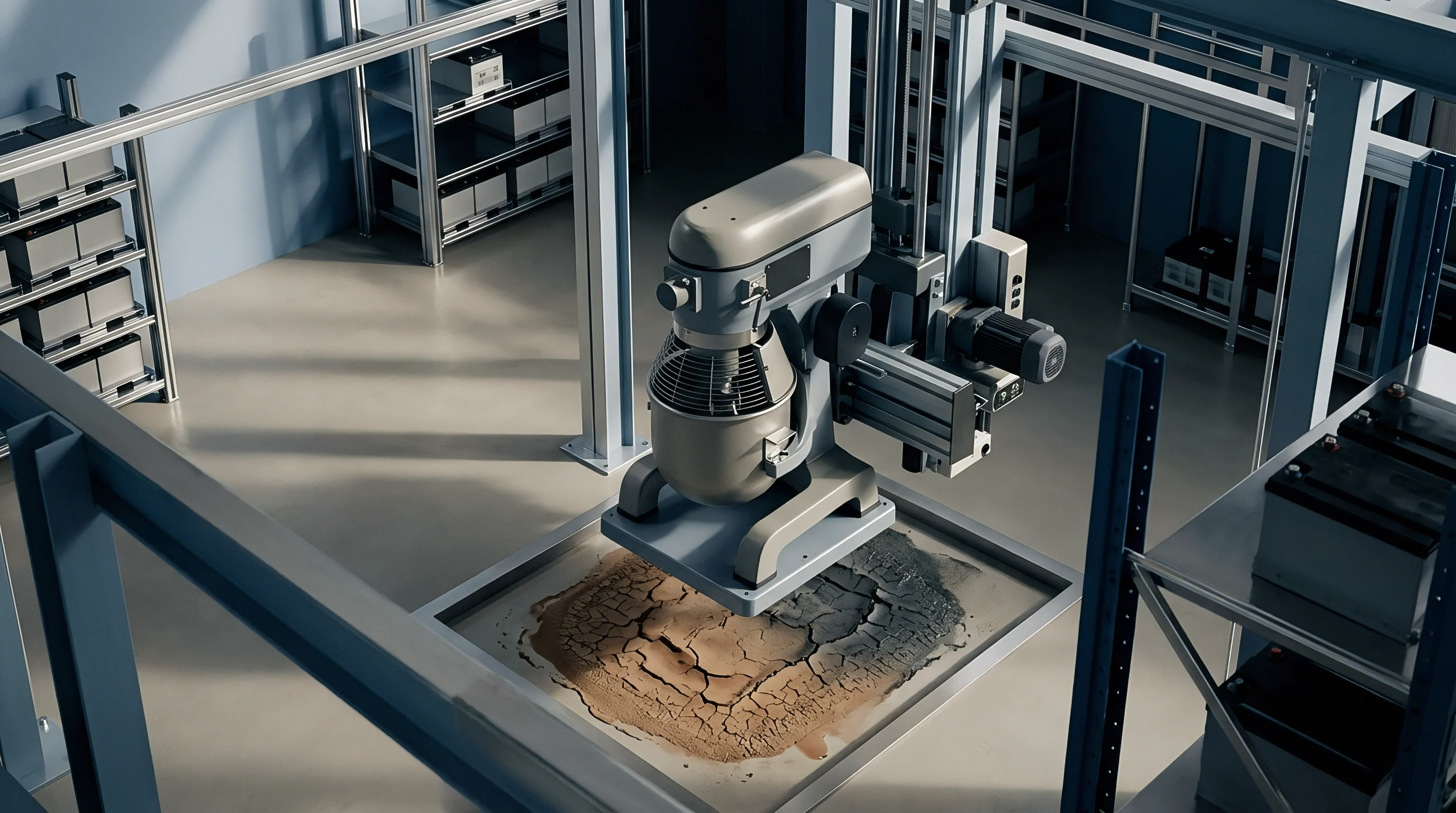
The solid electrolyte interphase is not a static, rigid solid. Inorganic components like lithium fluoride (LiF) and lithium carbonate (Li2CO3) build a semi-crystalline framework, while organic oligomers like lithium ethylene dicarbonate (LEDC) form an amorphous, ductile matrix. Under continuous stack pressure, this composite layer undergoes time-dependent plastic creep and viscoelastic stress relaxation.
Sustained compressive stress between 0.2 MPa and 1.0 MPa slowly forces organic interphase domains into porous interstitial voids. This lateral extrusion thins the passivation film directly beneath contact points, exposing pristine anode surfaces to active electrolyte. fresh reduction reactions initiate at these exposed areas, consuming solvent molecules and active lithium to rebuild the interface layer.
The plastic flow rate of organic lithium alkyl carbonates accelerates when stack temperatures exceed 45 degrees Celsius under continuous compressive loads.
Creep rates increase at higher temperatures. Operating cell modules at 45 degrees Celsius lowers the yield strength of amorphous interphase polymers, accelerating plastic flow under nominal clamping pressures. This deformation alters the stack’s baseline mechanical resistance, causing long-term decay of pre-load forces in spring-constrained module assemblies.
Microstructural Reorientation under Continuous Pressure
Sustained compression aligns polymer interphase chains parallel to the current collector plane. Microstructural reorientation lowers effective lithium-ion diffusion coefficients across the layer thickness, elevating interfacial transfer resistance (R_sei). Electrochemical impedance spectroscopy captures this compaction through a widening semi-circular arc in the mid-frequency spectrum.
The structural transformation of the interphase follows a multi-stage strain evolution model:
- Elastic Compression Stage instantly compresses macro-pores inside the organic interphase matrix upon initial pre-load application.
- Primary Viscoelastic Creep shows a logarithmic strain rate decrease over the initial 100 thermal cycles as molecular chains realign.
- Secondary Steady-State Creep maintains a constant creep rate driven by continuous chemical breakdown and organic film extrusion under steady stack pressure.
- Tertiary Mechanical Breakdown triggers localized interphase shear fractures when total strain exceeds film ductility limits, precipitating accelerated lithium consumption.
Electrolyte additives directly modify film ductility. Adding fluoroethylene carbonate (FEC) yields an inorganic-rich interphase dominated by LiF, raising yield stress and reducing plastic creep rates compared to standard vinylene carbonate (VC) formulations. Higher film yield stress maintains structural interphase integrity under extreme stack swelling loads.
Does sustained mechanical creep permanently alter interphase ionic conductivity at low ambient temperatures?


Rigidity
Buffer Interface Selection and Compression Curves
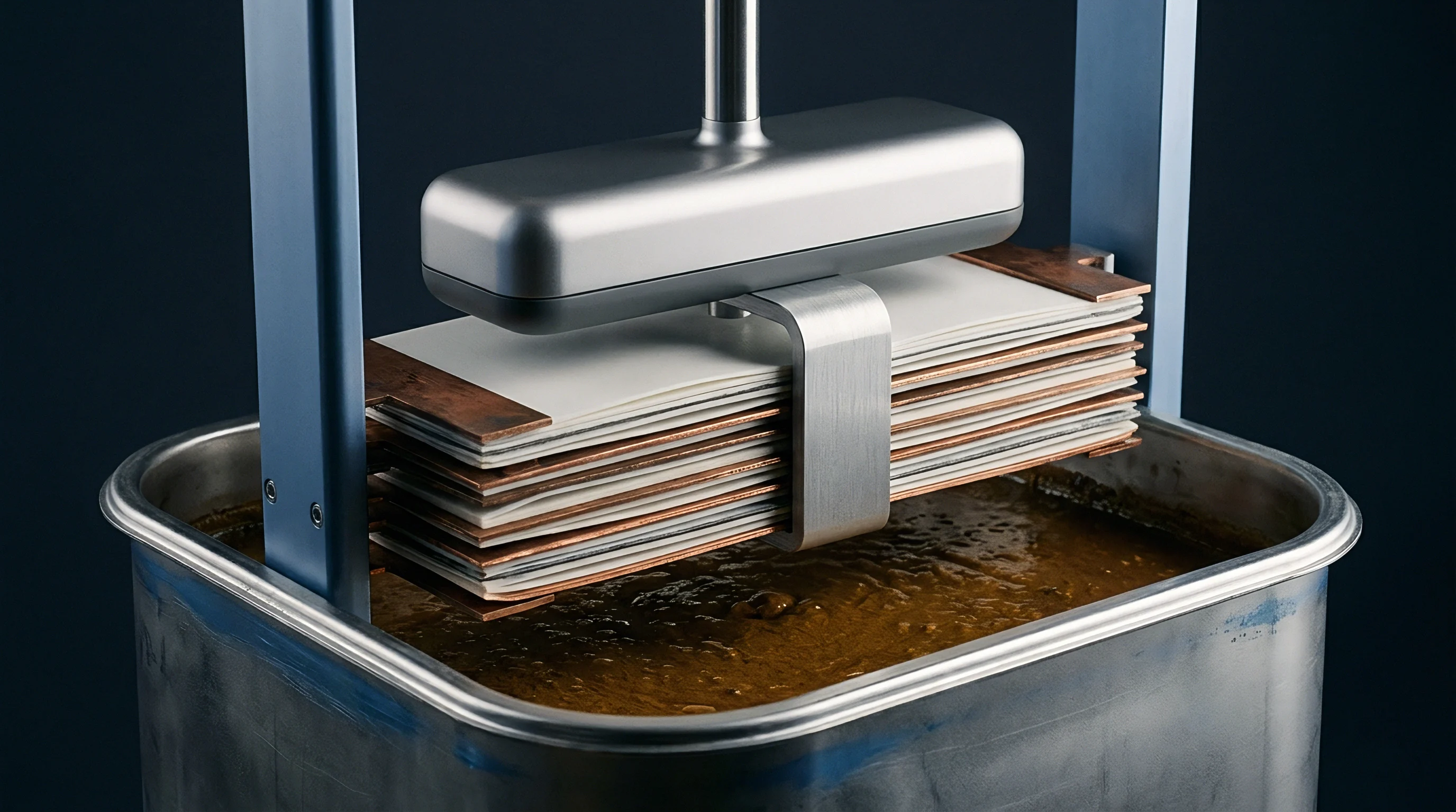
Accommodating irreversible thickness growth over a 10-year service life requires elastomeric compression pads between adjacent cells. Microcellular polyurethane foams and closed-cell silicone elastomers represent the dominant material choices for stack tension control. These pads act as non-linear mechanical springs, absorbing cell expansion while keeping module clamping pressures inside designated operating windows.
Stress-strain curves for microcellular polyurethane exhibit three distinct regions: an initial elastic response, a broad plateau governed by cell wall buckling, and a sharp densification region where open pore space collapses completely. Buffer pad design must target the plateau region to minimize stress rises during cycle swelling.
| Pad Material | Initial Elastic Modulus | Compressive Stress at 30% Strain | 10-Year Creep Relaxation Factor | Thermal Conductivity |
|---|---|---|---|---|
| Microcellular Polyurethane | 0.85 MPa | 0.22 MPa | 0.45 | 0.08 W/m·K |
| Closed-Cell Silicone Foam | 1.40 MPa | 0.38 MPa | 0.18 | 0.12 W/m·K |
| Aerogel Composite Sheet | 3.50 MPa | 0.85 MPa | 0.08 | 0.02 W/m·K |
Selecting buffer pad thickness involves balancing initial volume efficiency against long-term mechanical survival. Undersized foam pads undergo early densification. Once a pad reaches complete cell wall collapse, stack stiffness increases by two orders of magnitude, turning minor residual interphase growth into massive compressive loads that crush internal cell components.

Worked Load Progression in Module Tie-Rod Assemblies
Consider a 12-cell prismatic module utilizing 100 Ah LFP cells stacked in series. Initial cell thickness measures 27.00 mm with a manufacturing tolerance of plus or minus 0.30 mm per cell. The structural frame employs steel tie-rods pinned to 15.0 mm thick aluminum end-plates.
Compression pads with a nominal thickness of 2.00 mm sit between every cell face.
Initial assembly pre-charge targets 0.20 MPa pressure across an electrode area of 0.045 square meters, yielding a initial clamping force of 9,000 Newtons. The elastic modulus of the tie-rods measures 210 GPa with a total tension rod cross-section of 120 square millimeters. Microcellular polyurethane pads exhibit an initial compressive strain of 25 percent under 9,000 Newtons.
After 3,500 full charge-discharge cycles, cumulative irreversible interphase creep and silicon particle expansion add 1.20 mm of thickness per cell. Total stack thickness expands by 14.40 mm across the 12-cell group. The foam pads absorb 10.80 mm of this growth, pushing pad compression strain to 70 percent, directly entering the steep densification region of the material stress-strain curve.
Remaining stack growth (3.60 mm) forces elastic strain into the structural tie-rods and deflects the aluminum end-plates. Tie-rod elongation generates 6,300 Newtons of added force, while end-plate bending contributes an additional 2,100 Newtons. Peak stack pressure rises to 0.38 MPa at full state of charge.
This stress increase compresses the polyethylene separator from its nominal 16-micron thickness down to 11.5 microns in the central cell region. Separator pore closure reduces local ionic conductivity by 38 percent. The resulting impedance rise accelerates localized cell aging and drops total pack power output.
Standard IEC 62660-2 test protocols specify module stress tracking under fixed mechanical boundaries during multi-year thermal cycling.
Dynamic pressure balancing prevents structural component fatigue over long operational lifespans. Elastic buffer selection must match the long-term chemical swell profile of the specific cell lot.

Metrology

In-Situ Measurement Protocols and Sensor Topologies
Quantifying solid interphase plastic creep requires decoupling transient thermal expansion, cyclic intercalative swelling, and permanent interphase layer accumulation. Metrology rigs utilize multi-point optical laser displacement sensors combined with inline load cells to track micro-meter strain increments inside climate-controlled chambers held to plus or minus 0.5 degrees Celsius.
Testing configurations split into constant-displacement and constant-force regimes. Constant-displacement fixtures utilize rigid steel frames with sub-micron deflection tolerances to capture force escalation profiles over time. Constant-force fixtures employ pneumatic actuators or calibrated spring packs to measure dimensional growth under fixed pressure baselines.
How Does Pad Viscoelasticity Shift Under Constant Strain?
Piezoelectric sensor arrays placed directly between cell interfaces provide dynamic pressure distribution mapping across active surface areas. Edge effects routinely generate force spikes 40 percent higher than central electrode region metrics due to separator wrap tension and pouch enclosure seal stiffness.
| Instrument Type | Measurement Range | Resolution | Thermal Drift Error | Primary Measurement Focus |
|---|---|---|---|---|
| Optical Laser Triangulation | 0 to 20.0 mm | 0.10 microns | 0.05 microns/K | Pouch Thickness Expansion |
| Piezoresistive Film Matrix | 0 to 2.5 MPa | 0.01 MPa | 0.40 %/K | Interfacial Pressure Map |
| Inline S-Beam Load Cell | 0 to 50 kN | 1.0 Newton | 0.02 %/K | Total Module Clamping Force |
| LVDT Displacement Transducer | 0 to 10.0 mm | 0.05 microns | 0.01 microns/K | Long-Term Creep Kinetics |

Baseline Verification Procedure
Verifying stack swelling claims requires a strict sequential test protocol:
- Mount fresh single cells or sub-modules into calibrated mechanical test fixtures equipped with inline force and displacement instrumentation.
- Apply specified initial pre-charge pressure at 25 degrees Celsius and allow mechanical stress relaxation for 24 hours to establish stable baseline dimensions.
- Execute three full formation cycles at C/20 charge and C/10 discharge rates to measure initial reversible intercalative swelling amplitude.
- Transfer test assembly to a 45 degree Celsius environmental chamber to accelerate interphase chemical reaction rates.
- Subject cells to continuous C/2 cycling while recording continuous thickness growth at 100 percent state of charge and 0 percent state of charge endpoints.
- Extract stress relaxation curves during scheduled 48-hour open-circuit rest periods every 250 cycles to isolate plastic creep components.
Data normalization requires removing fixture thermal expansion signatures. Sensor calibration certificates must list temperature correction coefficients across the full operational range from minus 20 to plus 65 degrees Celsius.
Discrepancies in baseline growth can stem from thermal chamber calibration variance rather than underlying interphase degradation.


Warrant

Contractual Boundaries and Pre-Charge Specifications
Managing long-term mechanical stack expansion demands clear technical and financial allocation between cell manufacturers, pack integrators, and end-system integrators. Cell datasheets defining cycle life under zero-pressure unconstrained conditions offer no legal protection when cells are clamped into rigid pack structures. Master service agreements must define precise physical boundaries, acceptable pressure ranges, and compliance baseline shifts.
Pre-charge force specifications on cell drawings establish initial manufacturing responsibility. If a cell supplier specifies an initial assembly pre-charge of 0.30 MPa plus or minus 0.05 MPa, the pack assembly facility must demonstrate process capability (Cpk greater than 1.33) for fixture tightening torques or press displacements during module build operations.
Irreversible thickness limits govern warranty claims for capacity fade. When cell thickness expansion exceeds drawing baseline limits prior to target cycle metrics, financial liability transitions to the cell vendor for unpredicted solid interphase growth or aggressive electrolyte consumption.

Responsibility Allocation Matrix
Documenting module structural parameters protects engineering investments throughout the battery warranty period:
- Cell Manufacturer Warranty Scope covers initial cell thickness tolerances, baseline interphase growth rates under fixed laboratory clamping pressures, and maximum safe internal pressure thresholds before seal degradation.
- Pack Integrator Engineering Responsibility includes total mechanical stack tolerance stack-ups, compression buffer selection, structural end-plate flexure limits under peak swelling, and enclosure safety margins.
- BMS Firmware Operational Scope mandates enforcing high-temperature dynamic charging power derating to limit interphase plastic creep acceleration during elevated thermal operating states.
Quality audit documentation must archive first-article inspection records for every batch of elastomeric compression pads. Material batch variations altering foam density by more than 5 percent destabilize module pressure trajectories across multi-year field deployments.
Section 14.3 of standard supply agreements mandates that cell thickness growth exceeding 8.0 percent of initial drawing dimensions voids supplier performance indemnities if module compression fixtures exceed 1.20 MPa maximum clamp pressure.