Amortization Seams for Mold Cavity Surface Treatment Failure Risk between Toolmaker and Molder
Decouple cavity surface treatment warranties from tool steel structural guarantees in procurement RFQs to allocate early recoating costs fairly.


Grain
Injection mold cavities for electric vehicle battery enclosures work under harsh mechanical and chemical conditions during high-volume production. Components such as structural cell carriers, module retaining frames, and high-voltage junction housings are routinely molded from engineering thermoplastics filled with short glass fibers and flame-retardant additives. Running materials like polyamide six-six with thirty percent glass fiber reinforcement, or flame-retardant PC/ABS blends, generates severe melt shear and corrosive outgassing against cavity walls.
Surface treatments on cavity steel protect tool life, preserve parting line shut-offs, and maintain consistent part ejection. The practical wear boundary of the core ultimately comes down to choosing between physical vapor deposition coatings, plasma nitriding, micro-textured laser graining, and nickel-polytetrafluoroethylene release layers.
Tooling engineers generally select cavity steel grades based on core mechanical toughness, thermal conductivity, and chemical resistance. High-spec builds pair chromium-alloyed martensitic stainless steels like AISI 420 or Stavax with hot-work steels like AISI H13 hardened to 48 through 54 Rockwell C scale. Bare tool steel, however, lacks the hardness needed to withstand continuous glass fiber impingement at high melt velocities.
Uncoated cavities suffer rapid wash near gates where resin velocities exceed thirty meters per second, with micro-cracks propagating along grain boundaries. Applying targeted cavity surface treatments lifts surface hardness from roughly 500 Vickers to over 2000 Vickers, protecting the base steel against abrasive wear while lowering ejection forces.
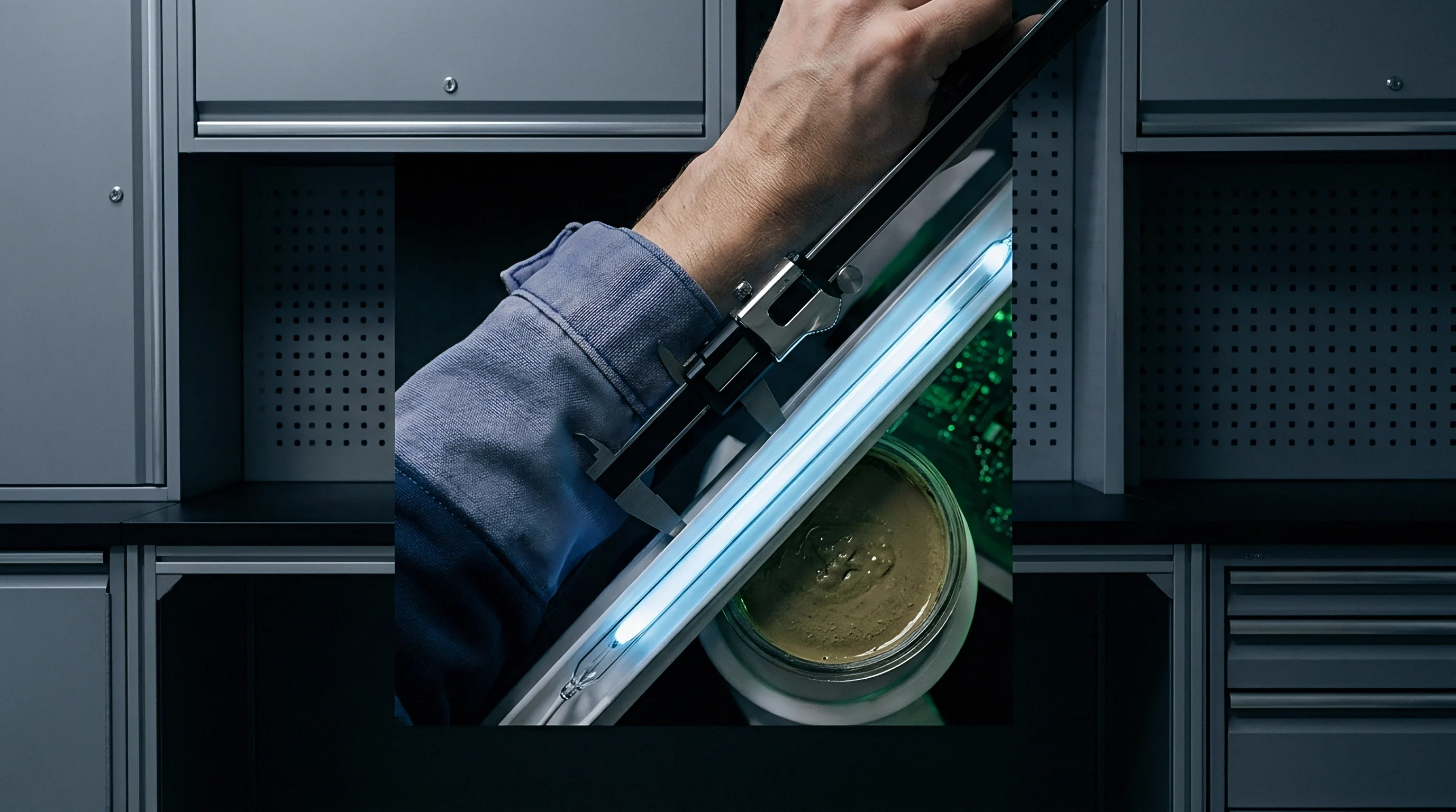
Interface Dynamics in Polymer Tooling Cavities
High-pressure injection molding demands tight thermal control and uniform microstructure across tooling faces. As molten polymer enters the cavity at injection pressures between 800 and 1500 bar, the surface coating experiences severe cyclic thermal shock. Melt temperatures for glass-filled polyamide run from 290 to 310 degrees Celsius against mold cooling circuits maintaining bulk steel at 80 to 120 degrees Celsius.
This sharp temperature gradient induces localized compressive stresses in thin hard coatings during filling, followed by tensile relief as the part cools and ejects. Additives such as brominated or red phosphorus flame retardants off-gas acidic volatiles at processing temperatures, adding chemical micro-pitting on top of mechanical shear.
Coating adhesion depends heavily on pre-deposition surface preparation. Toolmakers follow multi-stage polishing steps down to VDI 12 or Ra 0.1 microns before running deposition cycles. Micro-blasting with aluminum oxide media strips free iron contaminants and creates mechanical anchoring sites for physical vapor deposition layers.
Substrate cleanliness dictates atomic bond strength across the interface; any residue missed during ultrasonic degreasing leaves localized pinholes in the deposition film. These defects open paths for corrosive volatile compounds to reach the base metal, sparking sub-layer oxidation that eventually causes the coating to flake during production.

Coating Adhesion Mechanics under Molded Resin Shear
Substrates like AISI H13 or Stavax 420 establish the structural foundation for module housing tooling. Thin protective coatings applied via physical vapor deposition ~ such as chromium nitride or titanium aluminum nitride ~ are typically built up to thicknesses of two to five microns. These processes run at deposition temperatures around 400 to 500 degrees Celsius, aligning well with the steel’s tempering range so substrate hardness stays intact.
Plasma nitriding, by contrast, creates a diffusion zone 50 to 150 microns deep directly into the steel matrix, boosting hardness to approximately 1000 Vickers without forming a distinct boundary that might delaminate under impact.
Duplex surface treatments layer physical vapor deposition over a plasma-nitrided base to establish a gradual hardness transition. This gradient prevents thin exterior coatings from flexing into softer underlying steel under concentrated loads ~ a failure mode known as the eggshell effect. When abrasive glass fibers strike an unsupported physical vapor deposition coating, deflection in the base steel quickly fractures the ceramic top layer.
A nitrided transition layer supports that hard outer film, substantially improving scratch resistance and fatigue life over extended molding campaigns.
Physical vapor deposition coatings applied at 4 microns thickness lose cohesion when mold core temperatures exceed 180 degrees Celsius under 1200 bar injection pressure.
Laser texturing and chemical graining impart functional micro-textures onto mold cavity walls to control finished part appearance and tactile friction. Molded battery module covers require defined surface roughness textures to optimize thermal pad adhesion and automated mechanical gripping during pack assembly. As fiber orientation influences local surface erosion, laser texturing uses short-pulse laser ablation to carve precise micro-geometry directly into hardened tool steel, avoiding the hazardous chemical baths required for traditional acid etching.
Laser-ablated cavities display sharp topographical peaks that require secondary micro-polishing or light physical vapor deposition coating to smooth aggressive asperities that would otherwise cause mechanical binding during part ejection.
Surface treatments alter cavity thermal boundary conditions during polymer solidification. Nitrided layers and ceramic physical vapor deposition coatings exhibit lower thermal conductivity than bare tool steel, slightly slowing initial resin skin freezing upon cavity wall contact. This micro-second delay in skin formation allows molten polymer to fill intricate ribs and thin-walled structural webs before freezing, improving filling efficiency for thin-walled battery structural components.
Lowering friction across core pins reduces required ejection pin forces, minimizing stress whitening and warpage in molded flame-retardant enclosures. Toolmakers must balance coating hardness against brittleness, as excessively hard physical vapor deposition formulations chip along sharp cavity parting lines when tools slam shut under clamp force.
Disputes over coating warranties often center on whether mold temperature spikes during processing caused localized thermal expansion mismatches that stripped adherence.


Degradation
Fiber-reinforced engineering polymers erode mold steel through continuous abrasive contact at high flow velocities. In battery module housing manufacturing, structural brackets and cell separators require thirty to forty percent short glass fiber loading to meet structural stiffness requirements. Glass fibers possess hardness values around 1200 Vickers, significantly harder than standard 50 Rockwell C hardened tool steel.
As polymer melt flows through runner systems, restricted gates, and thin cavity walls, glass fibers align parallel to flow direction while exposed fiber tips scour cavity surfaces. Abrasive wear strips surface textures, rounds sharp draft angles, and erodes gate lands over high volume manufacturing campaigns.
Chemical degradation acts concurrently with mechanical abrasion inside mold cavities. Flame-retardant packages added to engineering polymers to achieve UL 94 V-0 flammability ratings emit halogen gases or phosphorus compounds at elevated melt temperatures. Moisture present in inadequately dried resin combines with volatile emissions during plasticolating to form aggressive acid compounds.
Acid condensates accumulate in unvented mold pockets, attacking unprotected steel grain boundaries and initiating stress corrosion cracking. Corrosion weakens the mechanical bond holding cavity coatings to underlying tool steel, accelerating coating flaking under fluid dynamic shear.
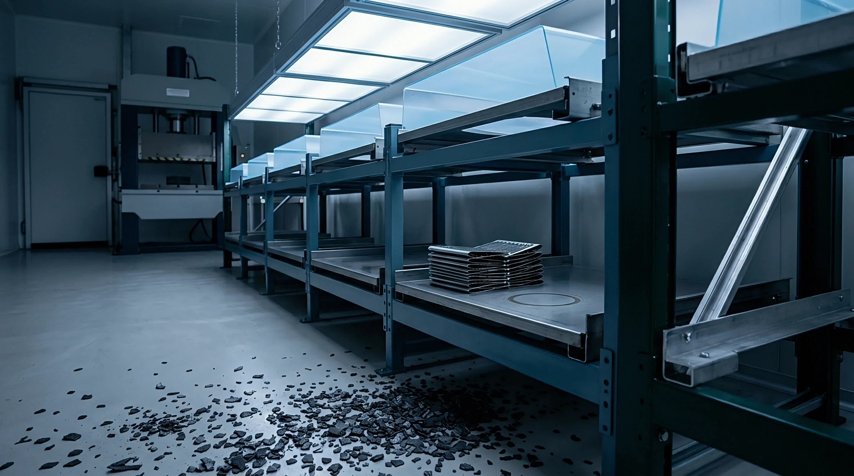
Tribological Wear and Chemical Attack Sequences
Glass fibers suspended within fluid polymer melts act like micro-cutting tools against cavity walls. Micro-abrasion proceeds through three distinct stages: polishing, micro-plowing, and micro-fatigue chipping. Initial molding cycles gently polish sharp surface asperities created during tool manufacturing.
Continued shot progression introduces micro-plowing, where high-speed fiber ends gouge microscopic grooves into soft steel matrices. Repeated cyclic stress from millions of resin passes induces micro-fatigue, causing localized surface steel grains to fracture and break free from cavity walls. This micro-scale breakdown increases local surface roughness Ra from 0.2 microns to over 1.5 microns in high-wear zones.
Corrosive outgassing targets tool steel intergranular boundaries, dissolving chromium oxides and creating micro-pitting along cavity faces. Mold venting channels designed at depths between 0.015 and 0.025 millimeters frequently clog with condensed flame-retardant volatiles. Blocked vents force acidic gases back into cavity surfaces during high-pressure pack filling stages.
Over thousands of injection cycles, these localized chemical pits coalesce into macro-scale surface pits, creating visible defects on molded cell carrier surfaces. Pitted cavity faces increase mechanical interlocking between molded plastic parts and cavity walls, raising required ejection forces and inducing mechanical stress in delicate molded components.

Can Mold Surface Flaws Compromise Dielectric Isolation?
Battery pack designers specify tight surface finish parameters on structural cell trays to eliminate micro-burrs and sharp flash. When mold cavity surfaces erode, part dimensions drift away from nominal engineering drawings. Cavity wall wear increases molded part thickness, causing dimensional stack-up issues across multi-cell pack module assemblies.
Worn mold core pins produce oversized alignment holes, leading to slop during automated robotic module assembly. Gate land erosion permits resin flash to form along part edges, requiring costly secondary manual deflashing operations that introduce handling risks into pack assembly lines.
Surface texture failure alters electrical creepage and clearance behavior across battery module insulators. Polymer busbar covers and cell isolation plates rely on pristine molded surface contours to prevent tracking along high-voltage paths under humid operating conditions. Eroded mold cavity texturing creates irregular surface ridges on molded plastic components that collect atmospheric dust and moisture during pack field operations.
Altered surface topography lowers electrical breakdown resistance across insulation boundaries, compromising safety compliance under IEC 60664 surface isolation standards.
| Coating Type | Primary Resin | Wear Mechanism | Failure Threshold Shots | Surface Roughness Shift Ra |
|---|---|---|---|---|
| Chromium Nitride PVD | PA66-GF30 FR | Glass fiber micro-plowing | 250,000 | 0.2 to 0.8 µm |
| Titanium Aluminum Nitride | PC/ABS UL 94 V-0 | Acid Outgas Pitting | 400,000 | 0.1 to 0.5 µm |
| Plasma Nitriding | PBT-GF20 FR | Adhesive wear and erosion | 150,000 | 0.3 to 1.4 µm |
| Diamond-Like Carbon DLC | PA6-GF40 | Thermal shock spalling | 180,000 | 0.1 to 1.1 µm |
| Electroless Ni-PTFE | PP-GF30 FR | Chemical dissolution | 80,000 | 0.4 to 2.0 µm |
Eroded mold core pins create subtle dimensional taper shifts in molded battery cell retainer pockets. Cell retainers hold cylindrical or prismatic cells in precise spatial grids to maintain consistent cooling air gaps or thermal pad contact pressures. When tool wear alters pocket dimensions by more than 0.05 millimeters, cell placement force shifts, leading to improper seating during automated cell insertion.
Misaligned cells generate uneven mechanical pressure against module cold plates, creating localized hot spots that accelerate battery cell degradation. Tool wear directly compromises module thermal management performance long before complete mechanical structural failure occurs.
Parting line wear creates heavy flash along component split lines. Battery enclosures require robust environmental seals meeting IP67 or IP69K ingress protection ratings to prevent water and dust entry into high-voltage battery compartments. When tool parting line surfaces erode due to clamp pressure and abrasive resin blow-by, molded sealing grooves deform or display excessive parting line flash.
Deformed gasket grooves fail to compress rubber seals uniformly, creating potential leakage paths for external moisture. Gasket sealing failures in field applications lead to high-voltage isolation faults, short circuits, and expensive pack warranty claims.
Standard IEC 60664 surface tracking distance calculations drop by two creepage tiers when cavity texture erosion creates longitudinal molded resin ridges exceeding 25 microns depth.
Monitoring cavity surface degradation demands disciplined tooling inspection schedules. Standard quality checks measure molded part dimensions but often fail to catch micro-scale surface texture breakdown during early stage tool wear. Wear begins quietly at high-velocity flow points, spreading across cavity surfaces before dimension shifts cross part rejection limits.
Implementing routine optical inspection of mold core cavities identifies coating erosion before part flash compromises cell clearance or dielectric isolation integrity.
Whether molders can reliably monitor localized tool erosion before part flash compromises cell clearance remains an open technical challenge across high-voltage pack lines.

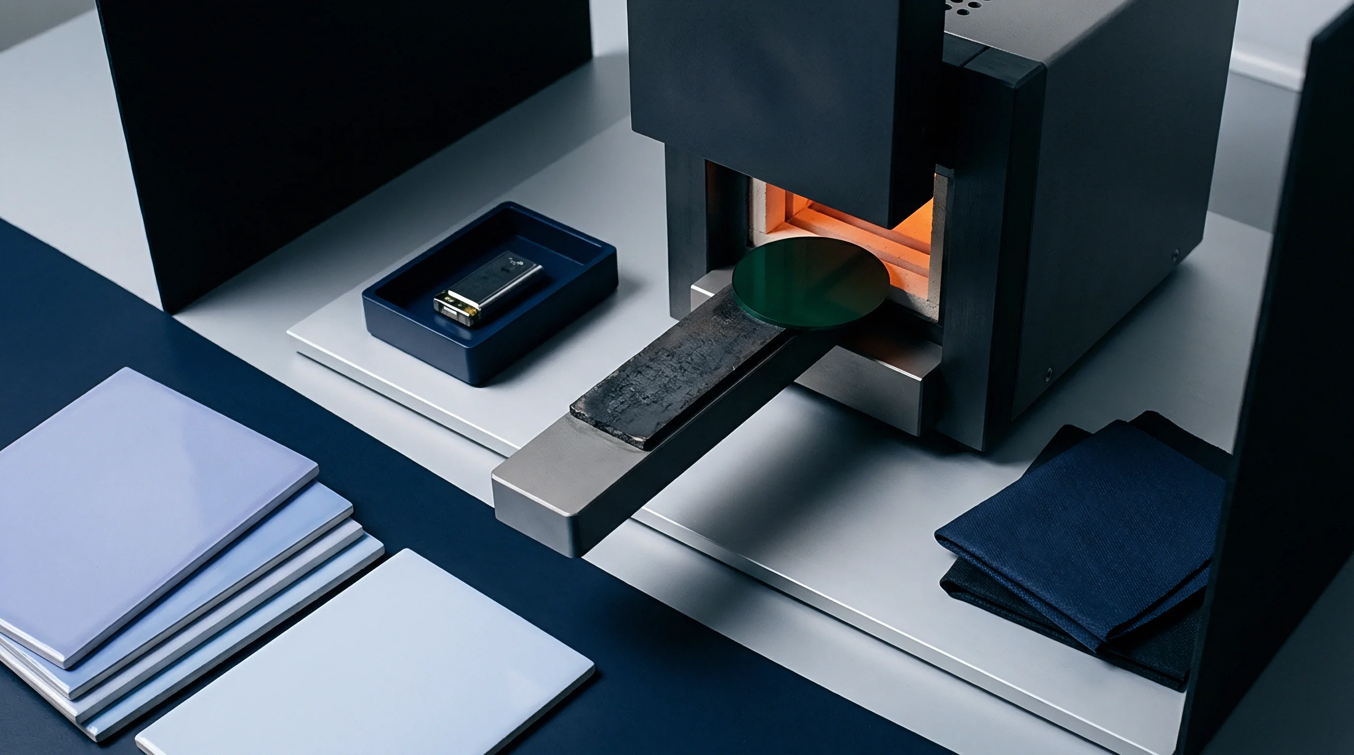
Split
Financing multi-cavity injection molds through piece-price amortization aligns early capital expenditure with initial production volumes. Battery pack buyers frequently choose to avoid paying full upfront non-recurring engineering tooling fees by agreeing to add an amortization surcharge onto each molded component delivered. A typical arrangement amortizes a $200,000 mold over a contract volume of 500,000 components, adding $0.40 per part to the baseline unit price.
This financial structure ties tool capital recovery directly to molding machine output, shifting early capital risk onto the molder or tool financing entity.
Commercial contracts break down when cavity surface treatments fail before reaching amortized production volumes. If a chromium nitride coating delaminates at shot 120,000 on a 500,000 shot amortization schedule, the mold cannot continue producing conforming parts without immediate cavity refurbishment. The toolmaker guarantees structural steel against mechanical cracking for 500,000 shots but limits coating surface finish guarantees to 100,000 shots due to resin abrasiveness variations.
The molder refuses to pay refurbishment costs, asserting that resin chemistry specified by the buyer caused accelerated wear. The pack buyer refuses to pay, claiming the amortized piece price already covers complete tooling maintenance over the entire contract volume.
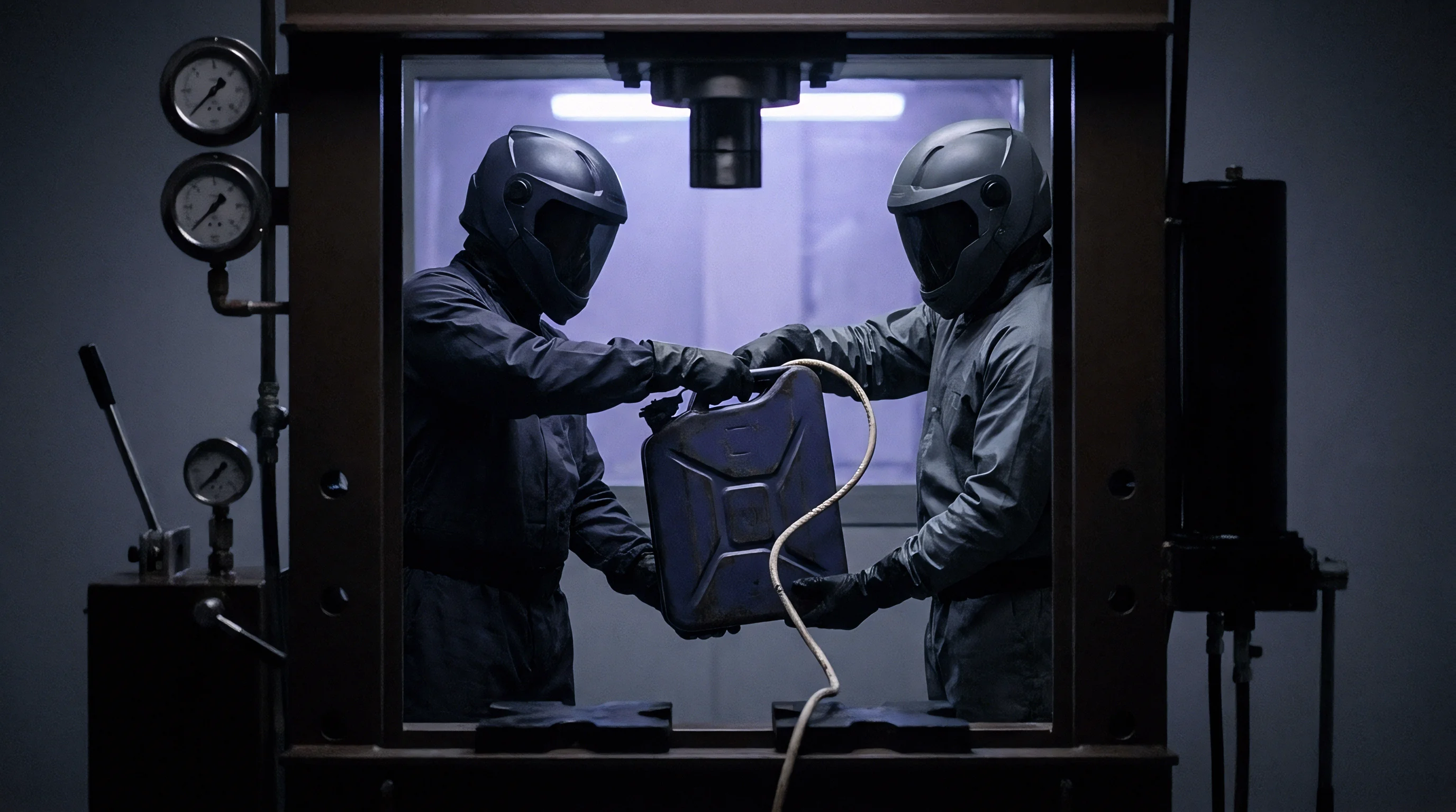
Financial Structure of Tooling Amortization Agreements
Original equipment manufacturers frequently structured tooling agreements to spread capital costs across the first 300000 production parts. Under standard piece-price amortization schemes, the molder buys the tool from the toolmaker, paying standard manufacturing progress milestones. The molder then recovers this capital investment by billing the buyer an agreed amortization surcharge per delivered part.
The buyer owns the physical mold asset only after the final amortization installment clears, creating a complex legal ownership seam while production runs are active.
Unamortized capital debt creates financial vulnerability when product volumes drop below forecast targets. If a battery module design changes prematurely after 150,000 shots due to cell chemistry upgrades, the buyer cancels part orders, leaving $140,000 in unamortized tooling capital unpaid on the molder’s balance sheet. Disproportionate wear on specific cavity surface treatments complicates early termination settlements.
Resolving unamortized balances requires precise contract definitions specifying whether tooling guarantees cover bare steel structural life or cavity surface finish integrity under abrasive resin molding conditions.

Worked Case in Early Cavity Recoating Mechanics
Consider a twelve-cavity mold producing cell retention brackets from thirty percent glass-filled polyamide six-six. The initial tooling cost was $180,000, amortized at $0.45 per shot across an agreed contract volume of 400,000 shots. The toolmaker applied a chromium nitride physical vapor deposition coating warranted for 150,000 shots under standard operating parameters.
At shot 135,000, severe coating delamination occurred in four cavity gates, causing heavy part flashing and dimensional out-of-spec conditions that halted battery module production lines.
Coating failure triggered immediate line shutdown during active runs. At the time of tool breakdown, the buyer had completed 135,000 shots, leaving 265,000 shots unamortized. The financial position stood at $60,750 in recovered capital, leaving $119,250 in unamortized tooling debt.
Stripping, re-polishing, and re-applying chromium nitride physical vapor deposition across all twelve cavities cost $22,500 in direct reconditioning fees. Press downtime incurred 36 hours of lost production time on a 500-ton injection molding machine, calculated at $400 per hour, generating $14,400 in operational losses. Scrap produced during failed batch production totaled 3,200 parts, representing $9,600 in wasted raw material.
| Cost Component | Total Value (USD) | Toolmaker Share | Molder Share | Buyer Share |
|---|---|---|---|---|
| Unamortized NRE Balance | 119,250 | 0 | 0 | 119,250 |
| Cavity Stripping & Recoating | 22,500 | 11,250 | 11,250 | 0 |
| Press Downtime (36 Hours) | 14,400 | 0 | 14,400 | 0 |
| Scrapped Resin Material | 9,600 | 0 | 4,800 | 4,800 |
| Re-qualification Inspection | 4,200 | 0 | 0 | 4,200 |
Cell holder dimensional variance rises by 14 percent when texture depth drops below five microns. Dispute resolution required analyzing machine maintenance logs, resin processing histories, and moisture drying charts. Machine logs revealed that the molder operated cavity melt temperatures at 315 degrees Celsius, exceeding the resin manufacturer’s maximum recommended processing window of 295 degrees Celsius.
This excessive thermal processing accelerated flame-retardant outgassing, breaking down physical vapor deposition coating adhesion ahead of the warranted shot limit. The toolmaker agreed to cover 50 percent of cavity reconditioning costs under their baseline warranty, while the molder absorbed press downtime and the remaining reconditioning balance due to processing parameter excursions.
Unamortized tooling debt creates friction between financial teams and line engineers. Tooling contracts can be structured to split recoating overhead evenly when resin batch variance causes early surface wear. Amortization schedules must decouple basic steel construction from consumable cavity coatings.
Treating cavity surface coatings as periodic maintenance items amortized over shorter, realistic shot intervals prevents sudden financial standoffs when aggressive glass-filled flame-retardant resins wear cavity surfaces ahead of structural tool failure.
Unamortized tooling balances belong on the molder’s balance sheet only when process log audits confirm parameter excursions beyond agreed window limits.
Contract terms establish liability limits. Allocation of tooling maintenance costs rests upon clear technical audits of mold maintenance logs and machine parameters. Establishing explicit agreement terms for cavity surface treatment maintenance avoids costly legal battles that stall production schedules during high-volume pack ramp phases.
Expedited shipping and re-qualification testing costs reached $18,200 during tool failure analysis.


Audit
Quality control teams rely on quantitative cavity metrology to track mold surface erosion before component geometry drifts out of specification. Traditional dimensional inspection of molded plastic parts provides delayed feedback, catching cavity failure only after parts fail drawing tolerances. Direct cavity inspection measures microscopic surface changes directly on mold steel, allowing maintenance teams to schedule cavity re-coating before production lines experience unscheduled downtime.
Modern cavity auditing combines non-contact optical profilometry, silicone replica sampling, and portable surface hardness testing.
Metrology protocols target high-wear cavity regions including injection gate areas, sharp internal ribs, core pin bases, and parting line lands. Baseline measurements recorded during initial tool commissioning establish reference parameters for surface roughness Ra, peak-to-valley height Rz, and texture pattern depth. Routine audits conducted every 25,000 shots monitor localized material loss, tracking micro-erosion trends over time.
Documenting cavity wear rates enables data-driven maintenance scheduling, replacing subjective visual inspections with precise physical measurement data.

Non Destructive Cavity Profilometry and Replica Inspection
High-resolution optical profilometers map three-dimensional surface topography without removing tool steel from the molding frame. White-light interferometry and laser confocal microscopy capture cavity surface profiles with sub-nanometer vertical resolution. When mold size or machine geometry prevents direct optical instrument mounting, technicians utilize high-fidelity silicone impression materials to create non-destructive cavity replicas, while portable microscopes inspect critical edges.
Special polymer resins cure inside mold cavities within ten minutes, capturing micro-surface details down to 0.1 micron fidelity for off-line optical profiling.
Silicone replica sampling permits quality teams to measure cavity texture depth degradation over extended production campaigns. Comparing replica profilometry data from shot 10,000 against shot 100,000 reveals exact wear locations and localized surface material loss rates. If texture depth on cell holder gripping faces drops from 15 microns baseline down to 6 microns, technicians schedule tool maintenance before part retention force falls below specified design limits.
Replica tracking eliminates guessing games, establishing empirical proof of cavity degradation trajectories.

Physical Verification Standards for Production Tooling
Standardized inspection protocols set clear threshold limits for allowable texture loss across critical cavity areas. DIN EN ISO 4287 defines standard surface profile parameters used to quantify cavity wear, including arithmetic mean roughness Ra, mean roughness depth Rz, and profile skewness Ssk. A positive shift in profile skewness indicates micro-pitting corrosion, while negative skewness changes reflect surface polishing caused by glass fiber abrasion.
Tool drawings specify maximum allowable deviation for key surface parameters, establishing unambiguous criteria for tool refurbishment.
Portable Vickers micro-hardness testers verify plasma nitriding layer depth and physical vapor deposition coating integrity. Hardness measurements taken along mold clamping faces and core pin shoulders detect localized thermal softening caused by press overheating or repeated thermal cycling. A drop in cavity hardness from 2000 Vickers down to baseline tool steel hardness of 500 Vickers confirms complete physical vapor deposition layer loss, alerting quality engineers that rapid steel erosion is imminent.
| Parameter | Measuring Technique | Baseline Value | Warning Threshold | Reject Limit | Action Required |
|---|---|---|---|---|---|
| Surface Roughness Ra | White Light Interferometry | 0.20 µm | 0.55 µm | 0.85 µm | Re-polish and re-coat cavity |
| Texture Depth (Laser Grained) | Silicone Replica Profilometry | 18.0 µm | 10.0 µm | 5.0 µm | Chemical re-etching required |
| Surface Hardness HV0.1 | Micro-Vickers Hardness Tester | 2100 HV | 1400 HV | 600 HV | Complete surface stripping & re-PVD |
| Parting Line Flash Gap | Feeler Gauge / Optical CMM | 0.005 mm | 0.020 mm | 0.040 mm | Spot grind lands and weld repair |
| Gate Land Wear Depth | Laser Confocal Scanning | 0.000 mm | 0.015 mm | 0.035 mm | Insert replacement or micro-weld |
Audit documentation forms the evidentiary backbone when arbitrating tooling warranty claims between toolmakers, molders, and buyers. Systematic recording of shot counts, resin batch certs, melt temperature logs, and optical profilometry reports eliminates opinion-based disputes regarding wear cause. When audit logs prove that molder processing parameters strictly adhered to specified limits while cavity coating failed prematurely, toolmakers honor coating warranties without protracted commercial friction.
- Clean mold cavity surfaces using isopropyl alcohol and clean micro-fiber wipes to eliminate resin outgassing residues.
- Apply optical grade silicone impression compound across the textured cavity zones, curing for eight minutes at ambient press temperature.
- Extract silicone replicas and mount them on a non-contact white light interferometry stage for surface roughness profiling.
- Compare measured arithmetic mean height and maximum height against baseline first-article inspection records.
- Log surface parameter shifts into the tooling maintenance database to predict coating wear trajectories.
A mold surface that shows localized dulling under white light inspection will produce parts with dimensional variation long before total coating delamination occurs.


Recovery
Restoring a worn mold cavity demands specialized chemical stripping and surface re-treatment techniques that protect underlying tool geometry. When auditing confirms that cavity surface treatments have reached end-of-life thresholds, tools undergo systematic refurbishment to restore original surface topography. Simple manual repolishing without removing residual hard coatings creates uneven cavity dimensions and ruins sharp detail geometry.
Refurbishment programs use controlled chemical stripping to dissolve degraded physical vapor deposition layers without attacking the hardened tool steel substrate.
Substrate preservation governs successful tool refurbishment cycles. Hardened steel cores like AISI H13 lose dimensional accuracy if stripping chemical baths contain uninhibited acids that etch bare tool steel. Acid immersion times must be strictly controlled, followed by immediate alkaline neutralization and ultrasonic cleaning.
Once stripped clean of old coating residues, cavity steel undergoes light micro-polishing or laser re-graining to re-establish specified surface texturing before re-applying fresh surface coatings.

Chemical Stripping and Cavity Re Texturing Protocols
Selective chemical stripping agents remove damaged nitrided or physical vapor deposition layers without attacking the hardened tool steel substrate. Chromium nitride coatings dissolve in alkaline potassium permanganate solutions, while titanium nitride layers strip using hydrogen peroxide and organic acid baths. Electrochemical stripping applies reverse electric currents to speed up coating dissolution while passivation additives shield underlying steel surfaces from hydrogen embrittlement.
Substrate inspection confirms complete coating removal before proceeding to re-texturing steps.
Re-texturing restored mold steel requires precise calibration to match original drawing specifications. Fiber laser re-texturing systems scan worn cavities, digitally mapping surface contours to align fresh laser ablation passes with surviving reference geometry. Laser re-texturing applies micro-scale grain textures onto polished steel faces with micron-level depth control.
Re-grained cavities undergo light stress-relief tempering before entering physical vapor deposition chambers for final protective coating re-application.

Downtime Impact and Press Capacity Allocation
Removing a multi-cavity tool from active production stops module housing output and disrupts pack assembly line scheduling. A complete cavity refurbishment cycle consumes seven to fourteen calendar days, including tool disassembly, transport to coating facilities, chemical stripping, re-texturing, physical vapor deposition coating, re-assembly, and bench sampling. Molders maintain emergency bridge tooling or safety stock buffer inventory to keep battery pack assembly lines running during scheduled mold maintenance events.
Refurbishment costs must be balanced against complete mold core replacement economics. Refurbishing a 12-cavity cell bracket tool costs approximately 15 to 25 percent of new tool construction capital. Repeated stripping and re-coating cycles alter steel metallurgy over time, limiting maximum refurbishing cycles to three or four instances over a mold’s operational lifespan.
Tracking cumulative refurbishment cycles ensures tool engineers replace aging mold cores before subtle metal fatigue induces catastrophic tool frame failure.
Repeated chemical stripping cycles soften tool cavity steel lands and accelerate dimensional parting line drift.
- Substrate etching occurs when chemical stripping baths exceed recommended immersion times, causing pitting in tool steel cavities.
- Dimensional shrinkage happens during repeated polishing operations, widening component wall thickness tolerances across internal ribs.
- Coating interface stress arises when new physical vapor deposition layers apply over residual nitride diffusion layers without complete surface reactivation.
- Texture mismatches develop when manual re-etching fails to match original laser graining depth across complex curved cavity side walls.
Planning scheduled refurbishments based on empirical audit metrics prevents emergency tool failures that cause unplanned production line stoppages.
Section 14.3 of the updated Master Tooling Agreement mandates that toolmakers re-apply cavity surface treatments at their expense if failure occurs within 100000 shots of documented refurbishing.


Clause
Clear legal and commercial contracts eliminate ambiguity around tooling surface longevity before purchasing agents issue orders for high-cavitation molds. Standard tooling purchase agreements often contain vague warranty language promising five hundred thousand shots guaranteed without separating structural steel integrity from cavity surface coating wear. Aggressive flame-retardant polymers reinforced with thirty percent glass fiber erode unprotected cavity coatings long before tool base steel experiences mechanical failure.
RFQs must explicitly define separate performance metrics for structural steel life versus cavity surface treatment durability.
Risk allocation clauses establish clear financial boundaries between toolmaker, molder, and battery pack buyer. Procurement contracts specify precise operating envelopes, locking down melt temperature ranges, injection speeds, maximum moisture limits, and approved resin manufacturer part numbers. If a molder substitutes an unapproved resin grade containing higher glass fiber content or cheaper flame-retardant packages to save cost, contract clauses void tool surface warranties and transfer full refurbishment liability onto the molder.

Structuring Tooling Service Level Agreements
Comprehensive procurement agreements define surface treatment warranties separately from tool steel structural guarantees. Master service agreements list expected cavity surface re-coating intervals as planned consumable maintenance items rather than unexpected tool failures. Amortization schedules reflect these realistic wear cycles, allocating a specific fraction of component amortization fees toward a dedicated tooling maintenance fund held to cover scheduled cavity stripping and recoating expenses.
Tooling service agreements mandate detailed machine logging procedures. Modern injection molding machines log melt temperature profiles, injection pressure curves, cycle times, and barrel residence times for every shot. Service level agreements grant buyers and toolmakers full access to machine sensor data logs when investigating early coating delamination or cavity wear.
Transparent data sharing prevents endless arguments over processing abuse versus defective coating application.

Risk Allocation for Resin-Induced Cavity Wear
Resin formulas containing flame retardants and glass fiber reinforcements cause predictable cavity surface degradation over extended production runs. Sourcing teams reduce commercial exposure by incorporating explicit technical standard clauses into mold manufacturing contracts. Contract clauses mandate baseline surface roughness testing during first article tool inspection, establishing non-negotiable reference parameters for all future wear audits.
- Resin specification lock binds the molder to qualified polymer grades and prohibits unapproved flame-retardant substitution.
- Amortization balance cap limits unamortized capital transfers if tooling surface breakdown requires premature replacement.
- Maintenance threshold triggers define exact shot intervals for mold inspection and preventative surface re-coating.
- Shared scrap liability divides scrap costs evenly between molder and buyer during initial tool trial re-qualification runs.
Integrating quantitative cavity metrology, transparent process monitoring, and explicit contract boundaries protects capital investments across complex battery tooling programs.
Establishing explicit wear boundaries in the original RFQ protects tooling investments and prevents costly commercial disputes across multi-year pack manufacturing programs.