Module Compression Pad Mechanics under Non Linear Swelling Force Profiles
Non-linear swelling forces mandate hyperelastic compression pads that hold module interfacial pressure between 0.02 MPa and 0.60 MPa over full cell life.


Compliance
Interfacial pressure inside an enclosed battery module changes non-linearly with state of charge and state of health. Lithium intercalation into graphite anodes causes an isometric volume change of 6 percent to 10 percent at the electrode level during full charge-discharge cycles. Inside a rigid prismatic housing or constrained pouch envelope, this microscopic swelling translates into substantial force against the module walls.
If unchecked, that force displaces internal electrolyte, crushes separators locally, and can structurally fail external tie-rods. Module mechanical design therefore requires an elastic boundary that can absorb non-linear growth while keeping contact stress above minimum electrochemical thresholds.
Cell swelling happens in two physical regimes operating over different timeframes. Reversible swelling follows the immediate movement of lithium ions between host lattices, producing cyclic pressure ripples with every charge cycle. Irreversible swelling develops over hundreds of thermal cycles, driven by solid electrolyte interphase growth, particle cracking, gas generation, and transition metal dissolution-redeposition.
Combined, these create a steep, non-linear load profile. Early in life at low state of charge, the force curve remains relatively flat. Late in service at high state of charge, force gradients steepen sharply once internal porosity is consumed.
A minimum contact pressure keeps current collector foils, anode coatings, separators, and cathode faces together. Dropping below 0.02 MPa allows internal layers to delaminate, which increases local impedance and disrupts current distribution. Too much pressure damages the separator permanently.
Compressing a ceramic-coated polyethylene separator beyond 0.60 MPa drops ionic conductivity, increases local heating, and encourages lithium dendrites to grow through microporous voids. The mechanical compliance window sits strictly between these two limits over the pack’s operating envelope.
Peak cyclic pressure on a 100 Ah prismatic cell reaches 0.42 MPa at full charge when constrained by an unyielding rigid boundary at 45 degrees Celsius.
Foam pads engineered for modules need hyperelastic resistance. A standard Hookean spring has a constant force-displacement rate, so using a linear material for a non-linear expansion distance leads to under-compression early in life or severe over-compression late in life. The foam needs to yield softly during initial displacement, offer a broad plateau of predictable modulus, and resist rapid densification before reaching maximum expansion.
Matching this hyperelastic response keeps the cell stack intact across its full service life.
Whether structural end-plates should yield under extreme late-life swelling or maintain rigid dimensions remains an open debate among integration specialists.

Elastomer
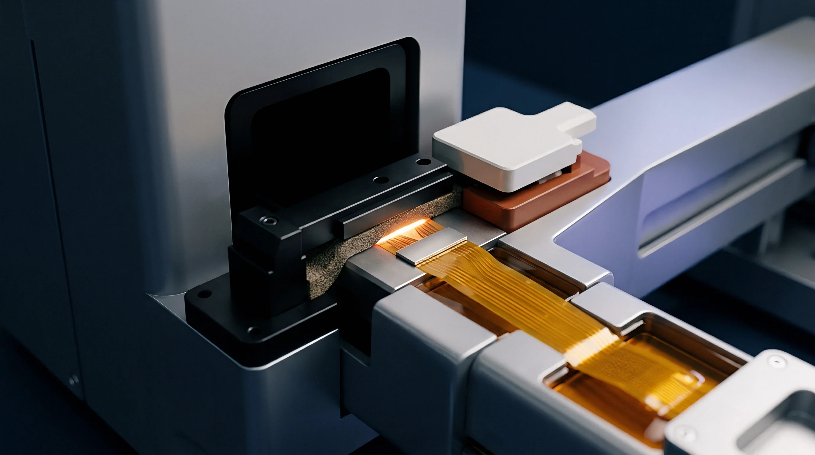
Polymeric foams chosen for inter-cell compression pads must hold elastic energy across broad temperature ranges and harsh chemical environments. Open-cell foams allow fluid transport but collapse under lower sustained loads, making closed-cell microcellular polyurethanes and silicone elastomers the standard choices for high-density automotive and stationary modules. Microcellular polyurethane offers high energy absorption and favorable stress-relaxation profiles at room temperature, though thermal aging above 60 degrees Celsius accelerates compression set.
Silicone foams maintain consistent properties from minus 40 degrees Celsius to 125 degrees Celsius, providing better long-term compression set resistance under steady thermal stress.
Stress relaxation is the loss of force over time when an elastomeric pad is held at constant deflection. As cell swelling drives the pad to a fixed strain, molecular chains reorient over hours and days, dissipating internal force. A pad with high stress relaxation cannot maintain minimum contact pressure when the cell later discharges and contracts.
Compression set, by contrast, is the permanent deformation remaining after a load is removed. High compression set leaves a permanent gap at low states of charge, breaking thermal paths to cooling plates and allowing cells to shift during mechanical shock.
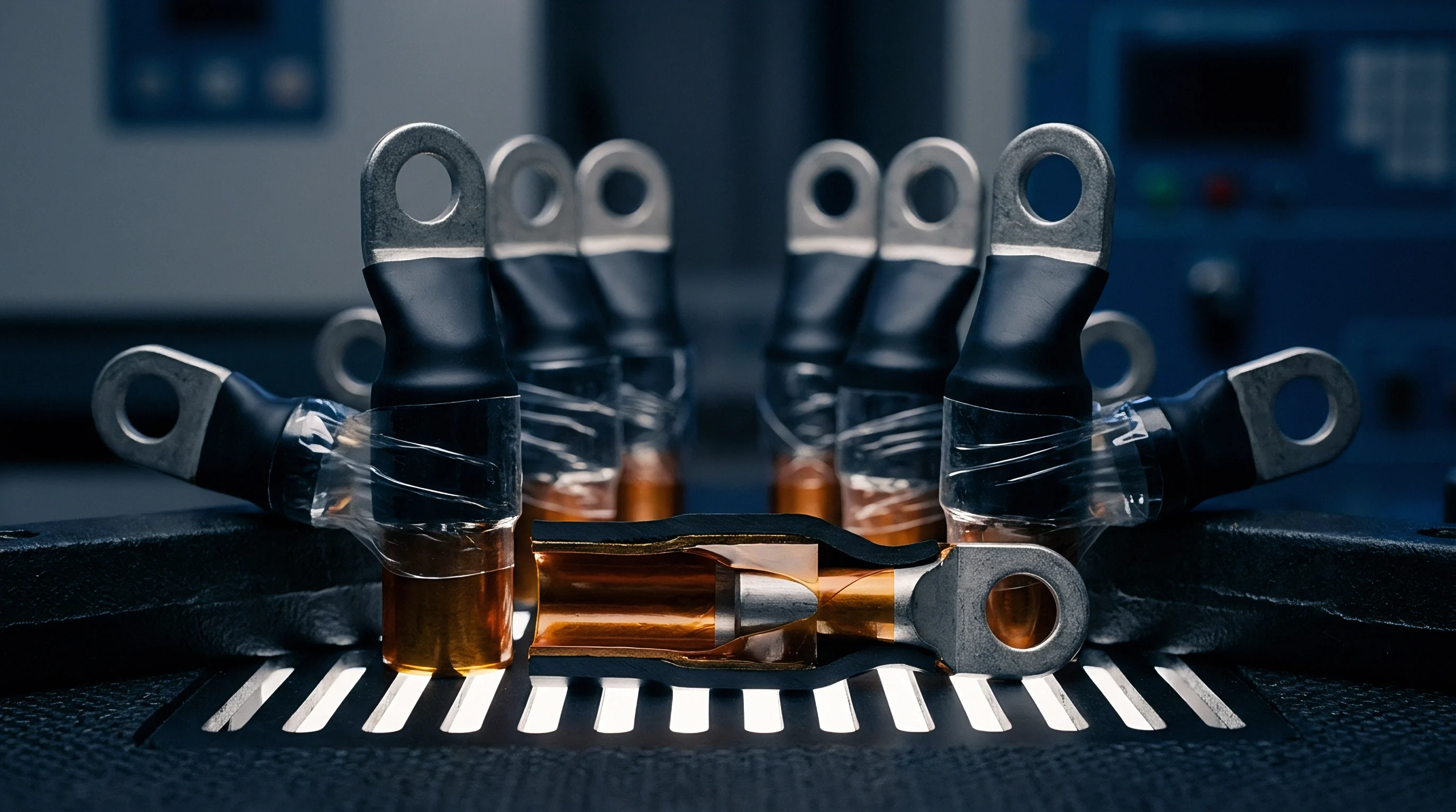
Material Property Comparison across Pad Chemistries
| Polymer Family | Density Range (kg/m³) | Tensile Strength (MPa) | Compression Set 70°C 22h (%) | Hyperelastic Region Limit |
|---|---|---|---|---|
| Microcellular Polyurethane | 240 – 480 | 1.2 – 3.5 | < 5.0 | 50% Strain |
| Medium-Density Silicone Foam | 250 – 500 | 0.5 – 1.8 | < 2.5 | 60% Strain |
| Cross-Linked Polyolefin (XLPE) | 100 – 200 | 0.8 – 2.1 | > 15.0 | 30% Strain |
| Fluorosilicone Sponge | 400 – 650 | 1.0 – 2.8 | < 4.0 | 45% Strain |
Evaluating compression pads requires testing under both static strain and continuous cyclic fatigue. Standard room-temperature stress-strain curves miss rate-dependent hysteretic behavior. Under cyclic displacement that mimics charge-discharge cycles, elastomeric pads exhibit dynamic mechanical hysteresis.
Internal friction during compression alters the force returned during cell contraction; loading follows a higher force path and unloading follows a lower path, forming a hysteresis loop that narrows over early cycles before settling into a steady state.
ASTM D395 Method B dictates compression set measurement under continuous 25 percent deflection at elevated temperature to qualify material elasticity.
Evaluating compression pads involves a systematic qualification sequence to verify performance before final design freeze:
- Material characterization requires measuring uniaxial compression stress-strain curves at strain rates from 0.01 per second to 1.0 per second.
- Thermal aging trials hold sample pads at 25 percent strain and 70 degrees Celsius for 1000 hours while tracking force decay.
- Cyclic fatigue testing subjects specimens to 3000 compression cycles matching the non-linear swelling displacement expected over module life.
- Fluid compatibility verification exposes stressed samples to vaporized electrolyte components to confirm chemical resistance.
Selecting a low-spec polyolefin foam purely to cut upfront component cost leads to loose modules, torn cooling-plate adhesives, and premature thermal failure across cell groups.
Expansion
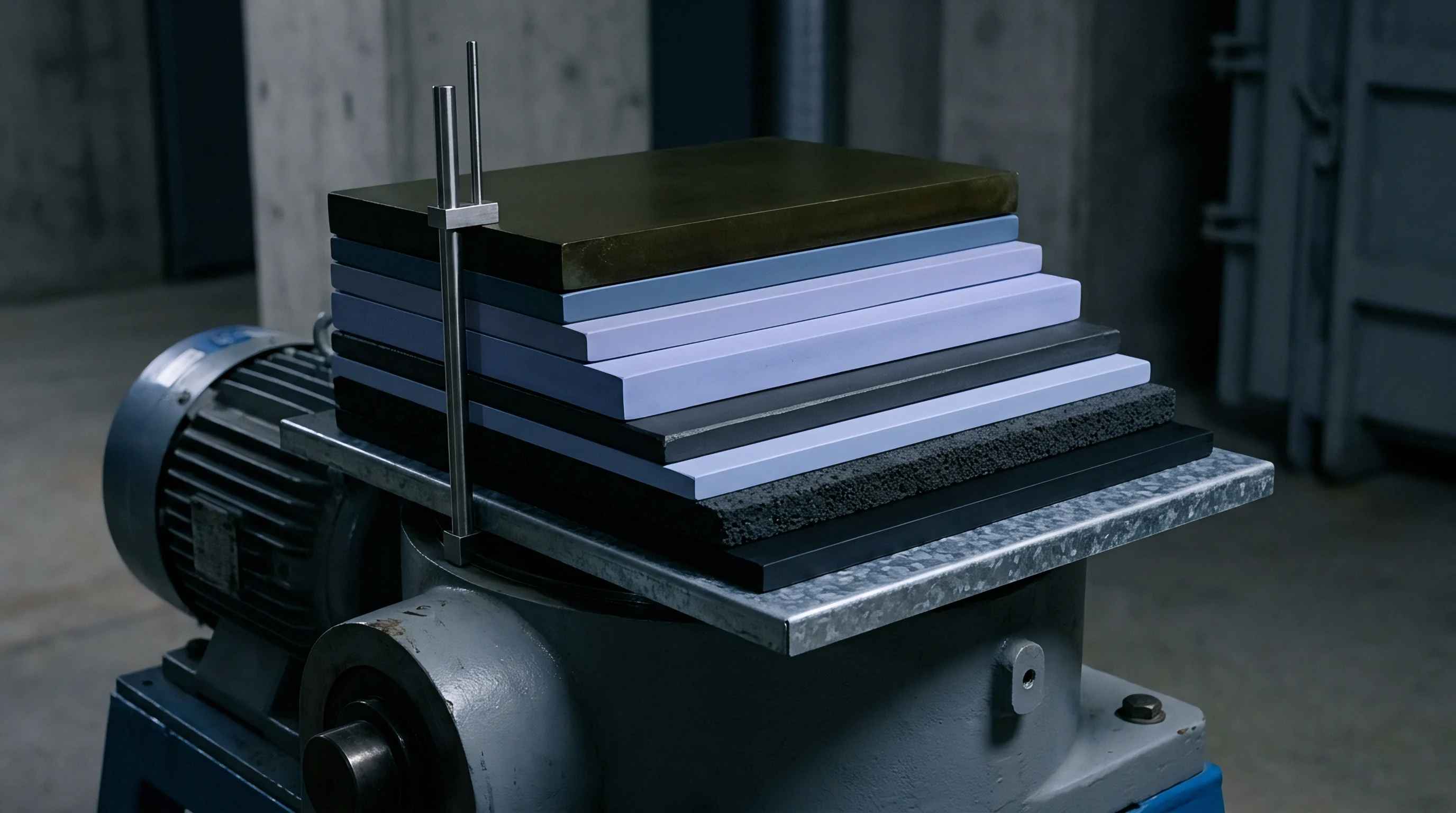
Accumulating dimensional tolerances across a multi-cell stack creates major mechanical stack-up problems. Prismatic cell specifications typically allow individual casing thickness variations of plus or minus 0.3 millimeters. In a 24-cell module stacked end-to-end, housing variations alone can shift uncompressed stack length by plus or minus 7.2 millimeters.
Adding pad thickness variations widens this tolerance band further. Module designs must handle this initial assembly variance without exceeding cell pressure limits before electrochemical swelling even starts.
Fast charging overlays transient thermal expansion onto electrochemical swelling. High current produces rapid internal heat, raising core temperature faster than the cooling system can extract it. Anode, cathode, and housing materials expand thermally, and when fast charging coincides with 100 percent state of charge, stack forces spike.
The compression pad must absorb this transient peak so module structural frames do not exceed their yield strength.
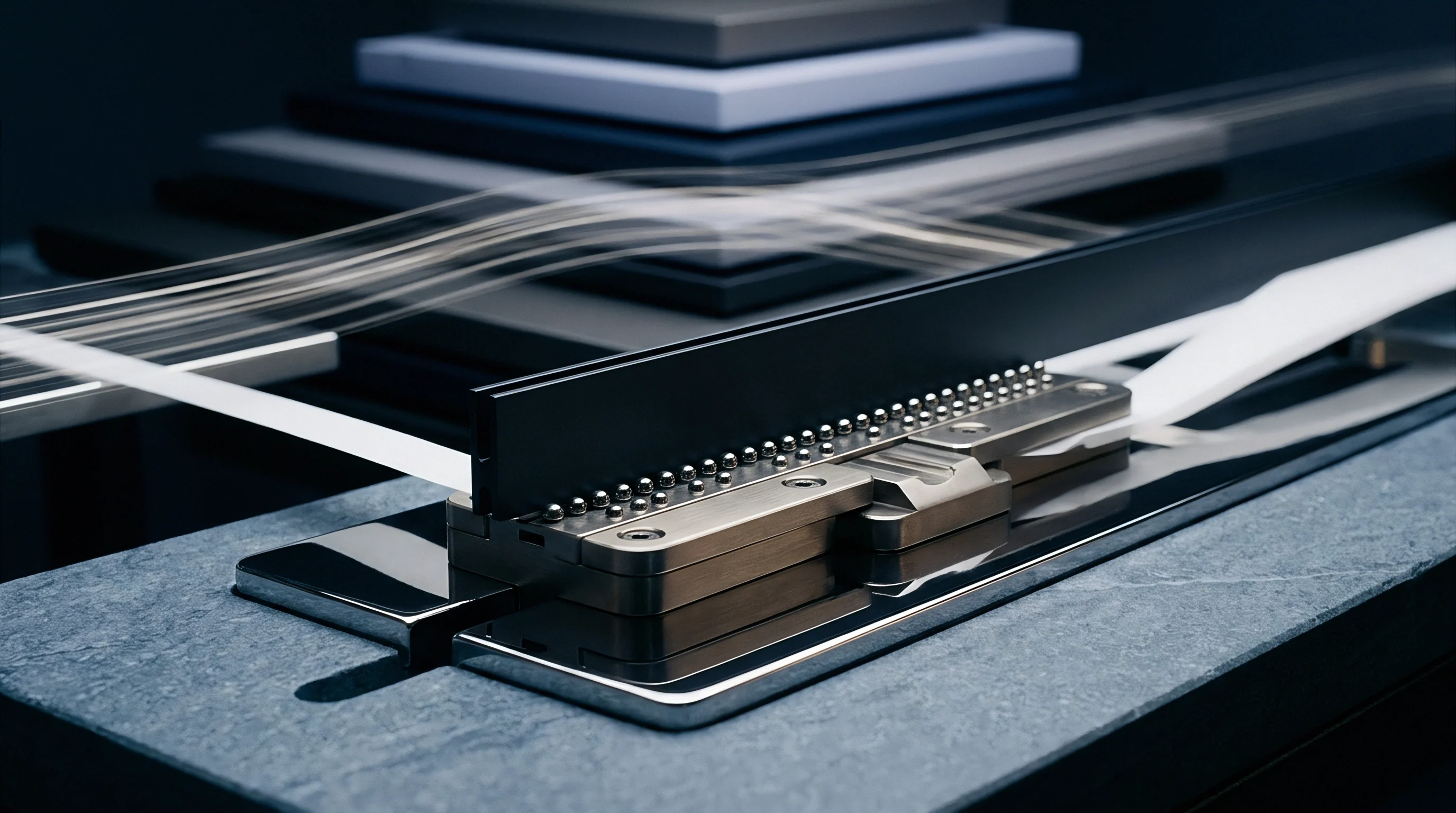
When Should Initial Preload Stress Be Redefined?
Preload calculations must be revised whenever cell form factors, chemistry, or tie-rod materials change. Lowering initial assembly preload accommodates aggressive swelling late in life, but risks cell movement under shock and vibration at zero percent state of charge early on. Raising initial preload prevents cell shift during transit, but compresses the pad near its densification point early, leaving little margin for irreversible swelling.
The setting balances minimum anti-rattle friction against late-life pressure limits.

Module Structural Mechanics under Variable Swelling Loads
| Lifecycle State | Single Cell Swelling (mm) | Pad Strain Level | Interfacial Force (kN) | Tie-Rod Tension (MPa) |
|---|---|---|---|---|
| Assembly Preload (0% SOC) | 0.00 | 15.0% | 1.2 | 45 |
| Begin Life (100% SOC) | 0.35 | 22.0% | 3.8 | 140 |
| Mid Life (100% SOC) | 0.80 | 31.0% | 7.5 | 275 |
| End Life (100% SOC) | 1.40 | 43.0% | 14.2 | 520 |
Dynamic force growth within module structures induces several distinct failure modes:
- End plate bowing occurs when lateral expansion forces exceed end-plate flexural rigidity, concentrating pressure along cell outer edges while reducing core contact.
- Tie rod necking develops under sustained late-life pressure peaks when tensile stress exceeds material yield limits.
- Cooling interface shear arises when differential cell growth drives lateral movement across rigid cooling plate adhesive layers.
- Busbar solder joint fatigue develops as cyclic stack expansion shifts cell terminals relative to fixed interconnect ribbons.
Cells expand within specified bounds under controlled bench testing, but real module structures impose non-uniform external stiffness constraints that alter localized force profiles.

Constraint
Sizing compression pads requires solving overlapping structural equations. Consider a 12-cell prismatic module held by rigid end-plates and steel side straps. Each cell has a nominal uncompressed thickness of 30.00 mm with a manufacturing tolerance of plus or minus 0.20 mm.
Maximum allowable interfacial stress at end of life (100 percent state of charge) is 0.50 MPa. Minimum allowable stress at begin of life (0 percent state of charge) is 0.05 MPa to prevent layer separation. Reversible expansion per cell is 0.40 mm, and irreversible expansion reaches 1.20 mm per cell at end of life.
Pad selection targets a closed-cell silicone foam with a hyperelastic stress-strain profile. The material exhibits a stress of 0.05 MPa at 12 percent strain and 0.50 MPa at 40 percent strain. Strain beyond 45 percent causes sharp densification and a steep pressure spike.
The equations yield initial pad thickness, required initial assembly compression distance, and maximum strap tension.
Total cumulative swell provides the primary displacement input. Reversible expansion across 12 cells totals 4.80 mm, while irreversible expansion totals 14.40 mm, giving a maximum cell expansion of 19.20 mm across the stack. Nominal total cell thickness is 360.00 mm, with a cumulative tolerance band of plus or minus 2.40 mm.
Determining pad compliance volume relies on mapping the strain range between 12 percent and 40 percent, which provides a usable working strain window of 28 percent. Dividing the 19.20 mm stack growth by the 0.28 strain window yields a total uncompressed pad stack thickness of 68.57 mm. Distributed across 13 pad locations (between cells and at the outer ends), this requires an uncompressed thickness of 5.27 mm per slot.
Selecting a standard production thickness of 5.50 mm uncompressed per slot locks in the mechanical layout.
Designing compression pads without accounting for stack tolerance accumulation reduces operational module fatigue life by over 60 percent.
Module architecture development follows this numerical sizing procedure:
- Calculate maximum lifetime stack displacement by summing worst-case cell tolerances, maximum reversible swelling, and irreversible aging expansion.
- Identify the hyperelastic strain limits corresponding to target anti-delamination pressure and maximum allowable separator stress.
- Divide total maximum stack displacement by the allowable strain window percentage to determine total uncompressed pad stack thickness.
- Distribute pad thickness across inter-cell spaces and check shock stability at minimum compressed thickness.
- Verify strap and end-plate structural stresses under maximum compressed pad force using conservative elevated-temperature modulus values.
Specifying inter-cell gap dimensions on drawings without explicitly defining pad strain state under tolerance extremes risks receiving non-conforming mechanical assemblies.

Dossier
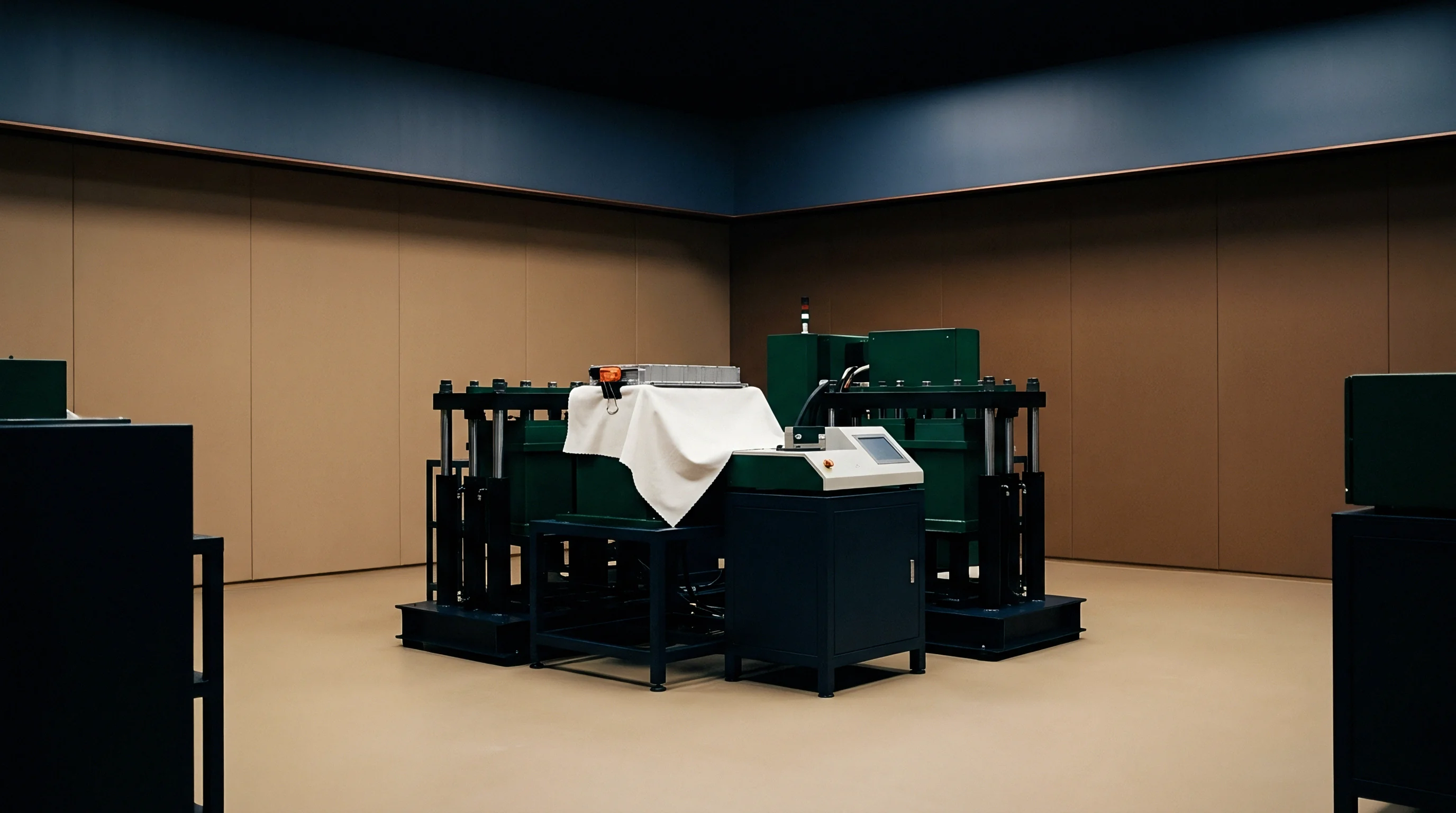
Qualifying compression pad materials requires test protocols focused on dynamic non-linear mechanical properties. Static testing fails to replicate the complex stress history inside an operating battery pack. Approval dossiers for module components should include high-temperature stress relaxation data, cyclic hysteresis curves, and dynamic mechanical analysis covering the full pack operating range.

Standardized Test Methods for Compression Pad Qualification
| Standard Designation | Primary Test Parameter | Specified Test Conditions | Acceptance Criteria Limit |
|---|---|---|---|
| ASTM D3574 Test C | Compression Force Deflection | Deflection at 0.83 mm/s rate, 23°C | Stress within ± 8% of curve spec |
| ASTM D395 Method B | Compression Set Under Stress | 22h at 70°C, 25% strain limit | Permanent set < 3.5% initial thickness |
| ISO 3386-1 | Stress-Strain Determination | 4th cycle compression loading curve | Plateau stress within target band |
| DIN 53517 | Continuous Stress Relaxation | 1000h at 60°C under fixed strain | Force loss < 18% from initial peak |
Cell manufacturers and pack integrators often dispute liability for swelling-induced structural failures. Cell vendors specify maximum swell limits based on unconstrained bench tests or flat plate clamps, while pack integrators build modules where stiffness varies across the frame. When non-uniform pack temperatures push local cell swelling beyond nominal expectations, isolating whether cell degradation or pad mechanical lockup caused the failure is difficult.
Quality dossiers must trace material stress curves, incoming pad thickness tolerances, and initial assembly preload records for every lot.
As a rule of thumb, compression pad thickness should equal roughly three times the maximum expected single-cell swelling distance to keep forces within safe limits.