Predictive Cavity Surface Degradation Modeling under Thermal Shock and Acidic Resin Outgassing
Coupling transient thermal strain models with Arrhenius acid dissolution rates predicts cavity pitting and fixes tooling refurbishment intervals.


Condensate
Acidic gases evolve from engineering thermoplastics during high-temperature injection molding of battery module carriers. When resins like polyphenylene sulfide, flame-retardant polybutylene terephthalate, and glass-reinforced polyamides hit the mold cavity at temperatures between two hundred ninety and three hundred forty degrees Celsius, intense thermal shear frees volatile fragments. These gases mix with residual air in the cavity, move toward low-pressure vents, and hit chilled mold steel surfaces kept between one hundred twenty and one hundred sixty degrees Celsius.
Rapid cooling drops the gas phase below its dew point, depositing a concentrated chemical condensate film on the micro-machined tool walls.
Pitting accelerates under acidic reflux, initiating aggressive corrosion on surfaces that need to hold micron-level tolerances across hundreds of thousands of molding shots. Standard battery pack designs rely on precision cell pockets, integrated busbar channels, and snap-fit retaining latches molded into single-piece polymer trays. As cavity steel degrades, critical retention dimensions drift, ejector pins bind, and molded cell pockets lose geometric parallelism.
Condensate corrosivity scales inversely with mold surface temperature while thermal fatigue damage scales directly with it.

Volatile Release Mechanisms in Structural Battery Polymers
Polyphenylene sulfide and flame-retardant polyamides undergo thermal decomposition when melt temperatures exceed normal processing thresholds. In polyphenylene sulfide formulations, thermal cleavage of end-chain thioether bonds releases sulfur dioxide, hydrogen sulfide, and low-molecular-weight oligomeric aryl sulfides. These airborne sulfur species react with atmospheric humidity inside the mold cavity to form sulfurous and sulfuric acids.
At the same time, brominated flame retardants added to meet UL 94 V-0 flammability standards break down under cyclic thermal loads. Thermal dissociation releases free bromine radicals, which pull hydrogen from the polymer matrix to form anhydrous hydrobromic acid fumes.
The aggressiveness of these outgassed compounds depends on the specific base resin and additive package running on the pack enclosure molding line.
- Sulfur dioxide off-gassing reacts with ambient moisture inside cavity vents to generate sulfurous acid with an active pH below two.
- Brominated hydro-radicals dissociate from polymeric flame-retardant packages above two hundred ninety degrees Celsius to produce corrosive hydrobromic acid fumes.
- Phosphoric acid condensates cause localized surface etching along low-temperature mold inserts during processing of red-phosphorus polyamide formulations.
- Formic acid vapors evolve through thermal shear degradation of polyoxymethylene and polyamides, stripping chromium passive films across gate regions.
Vents clog within five thousand shots as degradation byproducts build an insulating, acidic crust along the cavity parting line and vent registers. As vent depths drop from an initial fifteen micrometers down to three micrometers due to salt deposition, cavity backpressure climbs. This higher backpressure traps greater concentrations of acidic volatiles in the cavity, accelerating chemical attack on the tool substrate during successive production cycles.
| Resin System | Volatile Chemical Species | Mold Dew Point Temperature | Condensate Acidity | Primary Tooling Degradation Mechanism |
|---|---|---|---|---|
| PPS 40% Glass-Filled | SO2, H2S, Organosulfides | 142 °C | pH 1.8 to 2.4 | Intergranular corrosion, boundary pitting |
| PBT UL 94 V-0 (Brominated) | HBr, Alkyl bromides | 118 °C | pH 1.2 to 1.9 | Halide crevice corrosion, passive film stripping |
| PA66/6 (Red Phosphorus) | H3PO4, Phosphine fractions | 155 °C | pH 2.0 to 2.8 | General acid dissolution, phosphate crusting |
| PA6-GF30 (Organophosphate) | Formic acid, Phosphoric esters | 108 °C | pH 2.5 to 3.2 | Micro-cavitation, surface oxidation |

Where Does Cavity Condensation Concentrate?
Stagnant recirculation zones near mold ejector pins collect high concentrations of corrosive liquids. Fluid dynamics inside complex injection cavities create boundary layer separation points where gas velocities drop toward zero. As polymer fronts merge during weld line formation, trapped gases cannot escape through standard venting paths.
The resulting localized pressure spike drives gaseous acid molecules into micro-voids, electrical discharge machining witness marks, and grain boundaries across the cavity steel surface.
Condensation rates intensify along cooling channel boundaries where steep thermal gradients lower the steel surface temperature below the acid dew point. Tool designs incorporating conformal cooling circuits maintain lower localized wall temperatures to shorten cycle times, but these cooler zones induce preferential chemical condensation, turning high-velocity cooling regions into primary zones of corrosive attack where the chromium barrier dissolves rapidly.

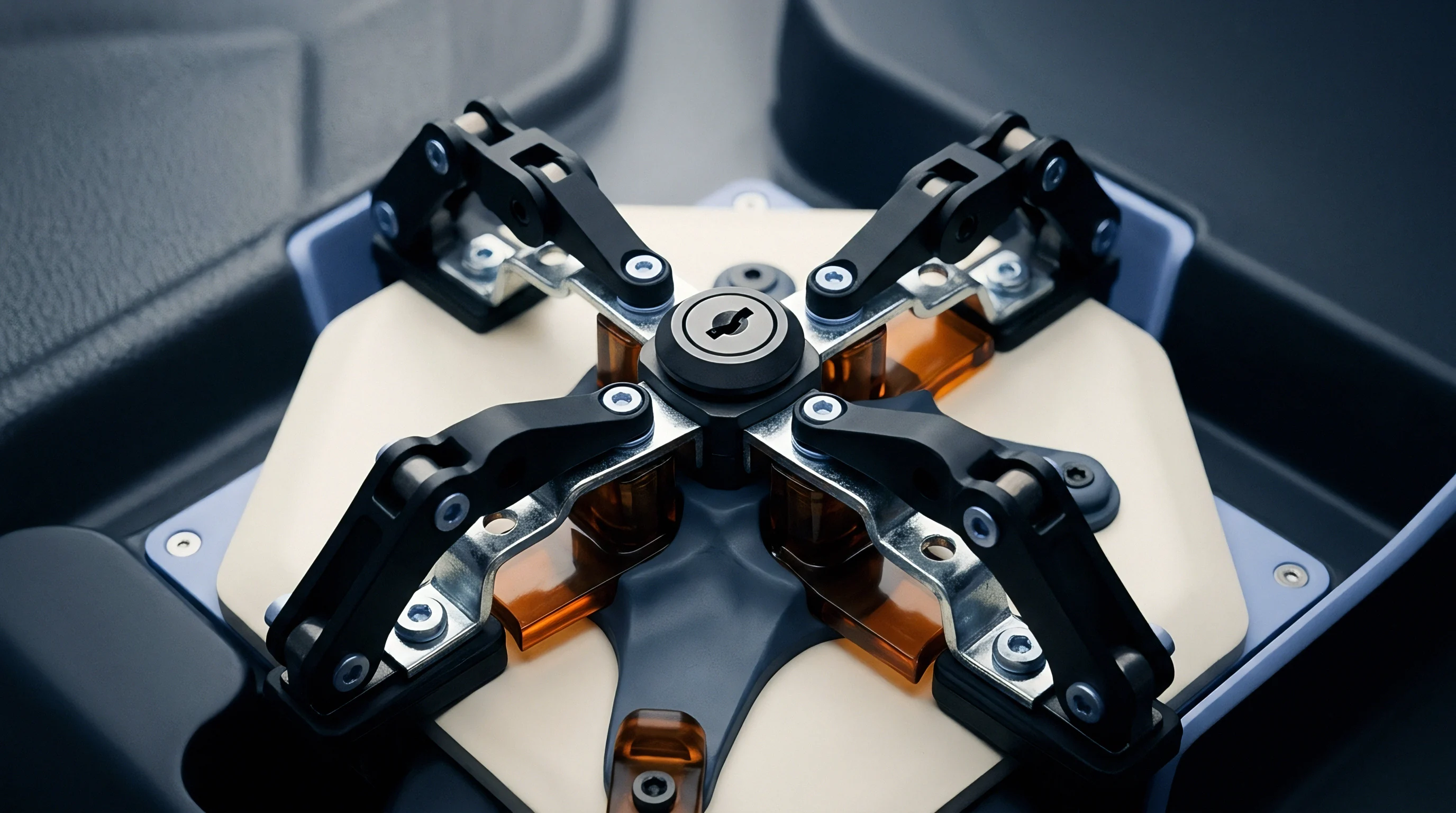
Steel
Tooling metallurgy determines base resistance against combined mechanical shock and acidic chemical attack. Mold bases in high-volume cell pack component manufacturing rely on specific tool steel grades that balance fracture toughness, thermal conductivity, and corrosion resistance. Martensitic stainless steels with twelve to eighteen percent chromium provide baseline defense against aqueous acid condensates, while hot-work tool steels deliver thermal shock resistance under rapid cyclic heating but offer minimal protection against halogenated or sulfurous chemical attack.
Standard mold cavity inserts machined from AISI H13 (DIN 1.2343) exhibit rapid surface crazing when exposed to continuous PPS or flame-retardant PBT processing. Lacking sufficient chromium to form a stable passive oxide film, the steel allows acidic condensates to attack iron grains directly. Tool steel selection fixes tool life.
Conversely, standard AISI 420 stainless grades (DIN 1.2083) resist chemical attack but suffer accelerated thermal fatigue cracking under aggressive cycle times where surface temperatures fluctuate across a wide thermal band.

Microstructural Passivation in Tooling Substrates
Chromium content above thirteen percent allows mold matrices to develop self-healing oxide films. This passivating chromium oxide layer shields the underlying iron matrix from direct electron exchange with acidic liquid condensates. In environments containing aggressive halide ions, such as hydrobromic acid outgassed from flame-retardant polymers, local passive layer breakdown occurs at microscopic inclusions and secondary phase carbides.
Halide ions displace oxygen atoms within the protective lattice, establishing microscopic galvanic corrosion cells between chromium-depleted grain boundaries and adjacent carbide precipitates.
Powder metallurgy steels resolve the carbide segregation problems characteristic of conventional ingot-cast alloys. In conventionally cast stainless steels, coarse chromium carbides form during solidification, depleting the surrounding iron matrix of the free chromium needed for corrosion resistance. Powder metallurgy alloys achieve a uniform distribution of sub-micron vanadium and chromium carbides, yielding uniform passivation across the entire cavity geometry and eliminating the preferential pitting paths that plague conventional tooling steels.
Cavity steel temperature differentials exceeding ninety degrees Celsius generate transient thermal stresses above four hundred megapascals at the resin contact boundary.

Multi-Layer Physical Vapor Deposition Barrier Mechanics
Applying chromium nitride or titanium aluminum nitride through physical vapor deposition interposes a dense ceramic shield over the mold base. Applied at thicknesses between two and five micrometers, these thin-film coatings display hardness values exceeding two thousand five hundred Vickers along with chemical inertness against concentrated organic and inorganic acids. However, monolayer coatings remain vulnerable to columnar growth defects: pinholes and micro-cracks extending perpendicularly from the coating surface down to the substrate allow acidic condensates to reach the tool steel base through capillary suction.
Multi-layer and nanostructured coating architectures prevent this through-thickness penetration. Alternating layers of chromium nitride and titanium silicon nitride disrupt columnar grain growth, deflecting micro-cracks along lateral interfaces. The resulting tortuous diffusion path prevents corrosive electrolytes from contacting the base steel before the production run reaches its refurbishment threshold.
Substrates with superior thermal conductivity survive acidic thermal shock longer than harder alloys with poor heat dissipation.

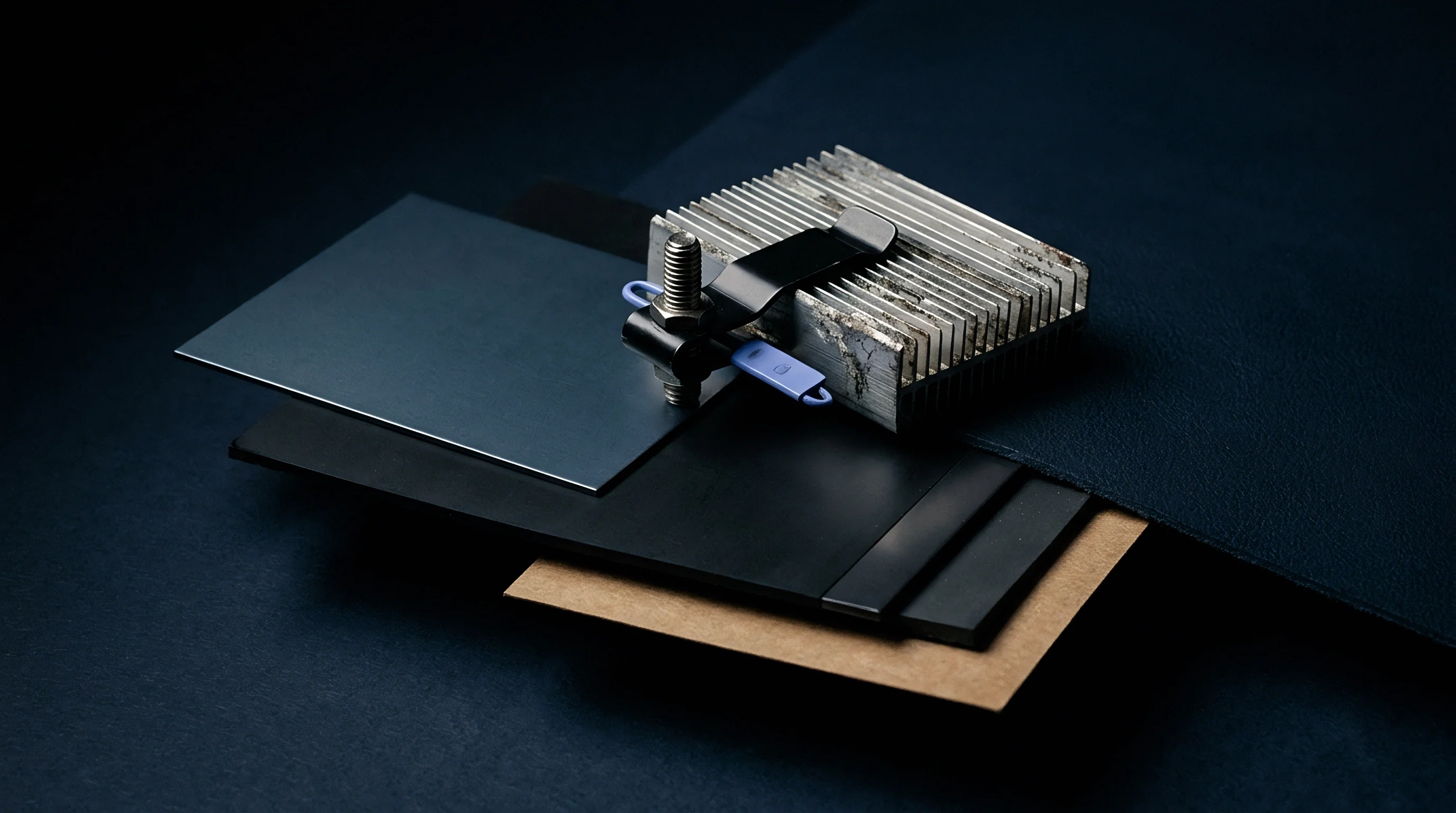
Kinetics
Predictive life modeling synthesizes transient heat transfer equations with mass transport and electrochemical rate formulations. The cavity surface degradation rate depends on cyclic interactions occurring during every injection shot. Early in the cycle, molten polymer at three hundred degrees Celsius strikes the tool surface, generating a rapid compressive thermal stress spike while outgassing acidic volatile fractions into the mold atmosphere.
As the tool cools and opens for ejection, the surface undergoes rapid tensile cooling contraction while chemical condensate settles into microscopic surface features.
Quantifying this degradation requires an integrated formulation that tracks surface roughness evolution as a function of shot count, thermal stress range, and chemical dissolution kinetics.

Coupled Thermomechanical and Electrochemical Damage Formulations
Cyclic temperature swings create transient boundary-layer stress states described by modified Coffin-Manson plastic strain equations. The cyclic thermal strain range depends directly on the thermal expansion coefficient of the mold steel, the transient surface temperature excursion, and Poisson’s ratio:
Thermal Strain Formulation: Delta epsilon_th = (alpha_th / (1 – nu)) Delta T_surface
In this mechanical relation, alpha_th represents the coefficient of thermal expansion, nu denotes Poisson’s ratio, and Delta T_surface represents the transient surface temperature fluctuation measured between resin injection and part demolding. Mechanical damage per cycle accumulates according to the Coffin-Manson relationship:
Fatigue Damage Component: D_fatigue = (Delta epsilon_plastic / (2 epsilon_f)) ^ (1 / c)
Here, epsilon_f is the fatigue ductility coefficient, while c represents the fatigue ductility exponent. Simultaneously, chemical corrosion occurs during the condensation residence window. The chemical dissolution rate of the cavity surface follows an Arrhenius-type electrochemical reaction driven by the local condensate acidity and surface temperature:
Corrosion Rate Formulation: R_corr = k_corr exp(-E_a / (R_gas T_surface)) ^ n
In this chemical relation, k_corr represents the reaction rate constant, E_a is the activation energy for steel dissolution, R_gas is the universal gas constant, denotes the molar concentration of the condensed acid species, and n represents the reaction order. The synergistic degradation model couples these two distinct phenomena. Mechanical thermal fatigue cracks expose fresh, unpassivated metallic grains to the acidic film, while chemical pitting creates microscopic notch defects that amplify the localized stress concentration factor:
Coupled Surface Degradation Rate: dRa / dN = C_1 (D_fatigue) K_t(pit) + C_2 R_corr
In this unified differential equation, dRa/dN represents the rate of arithmetic surface roughness increase per molding cycle N, K_t(pit) is the stress concentration factor induced by chemical pits, and C_1 and C_2 are empirical calibration constants established through laboratory testing.
Resin outgassing transforms micro-cracks from benign thermal stress relief features into aggressive chemical pitting sites.

Will Surface Passivation Suppress Crevice Growth?
Acidic pit incubation overrides protective surface layers once localized chloride or sulfur concentrations breach critical thresholds. When an acidic droplet condenses over a sub-micron surface micro-crack, oxygen diffusion into the crack tip is severely restricted. The crack interior acts as a microscopic anode where iron and alloying elements dissolve, while the passive exterior cavity surface serves as the cathode.
Hydrolysis of dissolved iron ions increases the hydrogen ion concentration inside the crevice, driving localized pH below one.
This autocatalytic acidification accelerates metal dissolution at the tip of the thermal fatigue crack, driving crevice growth rates ten to fifty times higher than general surface dissolution rates. Under these conditions, standard passivation mechanisms collapse entirely.
- Thermal shock transient loading imposes cyclic surface compressive plastic strain during polymer melt injection followed by rapid tensile reversal during water-circuit cooling.
- Condensate boundary saturation deposits acidic films within surface micro-asperities during the hold and decompression stages of the molding cycle.
- Passive oxide film dissolution exposes bare iron and alloy carbides to aggressive chemical attack, initiating microscopic galvanic pitting cells.
- Pit-to-crack transition transforms chemical etch pits into mechanical stress concentrators under cyclic thermal tensile loads, accelerating microcrack propagation.
- Surface roughness runaway leads to rapid micro-spalling of the mold steel, causing part demolding friction spikes and dimensional out-of-spec rejections.
The resulting micro-spalling strips mold steel particles away from critical shutoff surfaces, opening gaps along the tooling parting plane where flash then forms.
| Tooling Substrate / Coating | Coffin-Manson Exponent c | Activation Energy Qa (kJ/mol) | Critical Pit Depth (um) | Threshold Cycles To Spallation |
|---|---|---|---|---|
| AISI H13 (Hardened 50 HRC) | -0.52 | 42.5 | 4.2 | 35,000 |
| AISI 420 (DIN 1.2083, 52 HRC) | -0.61 | 68.3 | 8.5 | 85,000 |
| PM Tool Steel (Elmax, 58 HRC) | -0.68 | 84.1 | 14.2 | 220,000 |
| H13 + Monolayer CrN (PVD) | -0.55 | 92.4 | 6.8 | 110,000 |
| PM Steel + Multi-Layer AlCrN | -0.72 | 115.0 | 22.0 | 450,000 |
| Test conditions: 40% glass-filled PPS at 320 °C melt, 140 °C mold surface, cycle time 28 seconds, condensate pH 2.1. | ||||
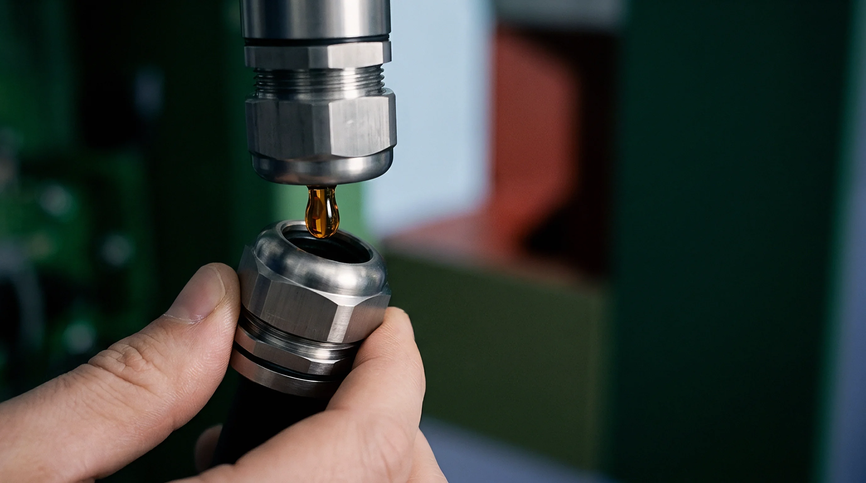
Worked Degradation Calibration across Twenty Thousand Cycles
A thirty-two cavity injection mold running forty percent glass-filled polyphenylene sulfide at three hundred twenty degrees Celsius operates under specific degradation conditions. The mold core inserts consist of through-hardened AISI 420 stainless steel heat-treated to fifty-two Rockwell C. Cavity cooling channels hold nominal tool surface temperature at one hundred thirty-five degrees Celsius, with a cycle time of twenty-eight seconds producing three thousand eighty-five shots per day across three operating shifts.
Under these operating conditions, the measured transient surface temperature excursion Delta T_surface reaches eighty-five degrees Celsius during initial melt impingement. Substituting this temperature excursion into the thermal strain equation with an expansion coefficient of eleven point eight times ten to the minus sixth per Kelvin yields a cyclic thermal strain of zero point one four percent. The Coffin-Manson fatigue calculation establishes a baseline mechanical fatigue life of one hundred eighty thousand cycles prior to microcrack initiation in an inert environment.
Chemical monitoring demonstrates an acidic condensate accumulation rate of zero point zero three milligrams per square centimeter per hour, yielding an active surface condensate film with a pH of two point two. The Arrhenius dissolution formulation yields an electrochemical material removal rate of zero point零零four micrometers per thousand cycles, though synergistic pit coupling accelerates this progression significantly. Chemical pits reach a critical depth of eight point five micrometers by cycle sixty-two thousand, shifting the stress concentration factor K_t(pit) from one point zero to three point two.
Whether chemical pit propagation accelerates faster under compressive thermal hold or tensile quench relaxation remains a subject of experimental dispute among tooling metallurgists.


Inspection
Metrology programs establish the wear state of high-precision molding surfaces before dimensional drift produces out-of-spec cell holders. Standard tool room maintenance routines relying on periodic visual checks fail to capture early-stage pitting and micro-crack networks hidden in deep rib geometries and cell retention pockets. Advanced inspection protocols implement non-destructive optical profilometry, high-resolution replica tape metrology, and acoustic emission monitoring directly linked to shot counters.
In high-density battery pack architectures, cell pocket center-to-center distances carry tolerances of plus or minus twenty-five micrometers across an entire seventy-two cell module carrier. A five-micrometer change in cavity surface roughness increases part ejection force by up to forty percent. Higher ejection loads induce severe residual stresses in thin-walled polymer pockets, warping cell retention tabs and misaligning internal busbar weld channels during downstream pack integration.
DIN EN ISO 4287 roughness thresholds define cavity retirement when surface skewness shifts from negative valleys to positive abrasive peaks.

Optical and Acoustic Metrology Gating
White light interferometry measures cavity roughness profiles down to sub-nanometer vertical resolution. By tracking surface topography according to DIN EN ISO 4287, quality engineers monitor specific mathematical parameters beyond basic arithmetic average roughness (Ra). The profile skewness parameter (Rsk) provides the earliest indicator of cavity degradation under acidic outgassing conditions.
A freshly diamond-polished mold cavity exhibits negative skewness, indicating a smooth plateau surface interrupted only by occasional lubrication valleys.
Chemical pitting rapidly shifts profile skewness into positive values, confirming the presence of sharp, protruding metallic asperities and micro-cratering caused by acid attack. Acoustic emission sensors mounted on the mold backplate detect high-frequency transient elastic waves generated when microcracks initiate and propagate through brittle surface layers. Real-time acoustic energy spikes signal active cracking before visible defects appear on molded polymer carriers.

Quantitative Criteria for Cavity Refurbishment
Surface roughness limits dictate when a mold insert enters bench repolishing or strip-and-recoat processing. Operating a corroded cavity beyond defined surface thresholds damages the structural integrity of molded pack enclosures, altering demolding friction profiles and accelerating core pin deflection.
- Arithmetic average roughness exceeding zero point four micrometers triggers immediate cavity withdrawal from the production press for surface benching.
- Maximum profile peak height surpassing two point five micrometers indicates advanced pitting and micro-spalling across primary shutoff faces.
- Negative skewness inversion marks the transition from harmless micro-valleys to protruding abrasive asperities that scratch molded battery pack parts during ejection.
- Acoustic emission energy spikes above thirty decibels during the injection stroke signal active microcracking within the hardened cavity surface layer.
When wear reaches these defined thresholds, continuing production risks catastrophic damage to the tooling base. Weld repairs alter local grain structure, while premature cavity retirement combined with unexpected dimensional drift of battery cell retention features forces unscheduled tooling rebuilds and halts assembly lines.
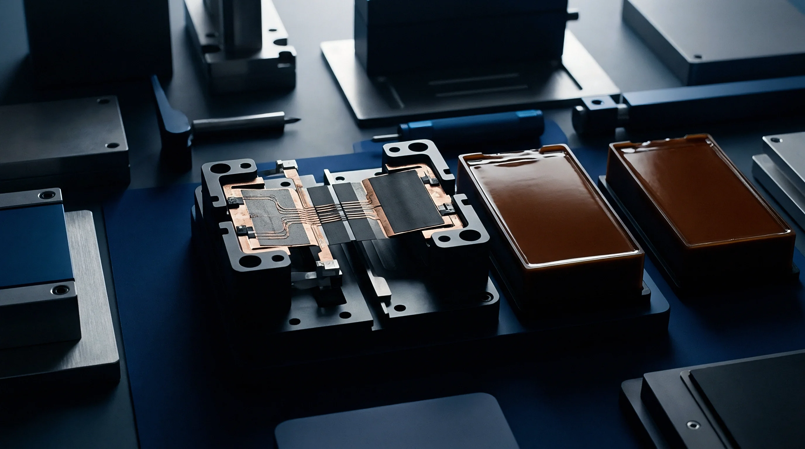

Tooling
Capital expenditure models quantify total cost of ownership across the operational lifespan of high-volume battery pack components. Tooling contracts for electric vehicle battery modules frequently underestimate the financial impact of cavity surface degradation. High-temperature flame-retardant polymers degrade standard mold steels rapidly, turning a tool budgeted for one million cycles into an operational liability requiring rebuilding every seventy-five thousand shots.
Resolving this discrepancy requires explicit commercial boundaries between the battery pack design firm, the tier-one injection molder, and the tooling vendor.
Tooling quotations that select baseline AISI H13 steel to lower upfront Non-Recurring Engineering (NRE) charges transfer immense operational costs to downstream production phases. When abrasive glass fibers combine with acidic condensates, baseline tools suffer rapid washout around injection gates and severe pit corrosion along parting lines. The resulting scrap rates, press downtime, and emergency cavity replacements quickly erase initial capital expenditure savings.

Contractual Allocation of Cavity Wear in RFQs
Procurement documents define whether cavity degradation caused by corrosive resin outgassing falls under routine maintenance or capital refurbishment. Tier-one injection molders typically draft quotations categorizing acid-induced cavity corrosion as abnormal wear attributable to aggressive polymer formulations selected by the battery pack architect. Under these terms, cavity repolishing, stripping, and replating expenses pass directly to the buying organization as billable tooling maintenance.
Strategic procurement teams avoid this financial trap by embedding strict performance specifications into the initial Request for Quotation (RFQ). The RFQ mandates that the mold builder deliver documented steel certification dossiers, heat treatment hardness test reports, and PVD coating thickness verifications. The specification establishes minimum shot-life guarantees under specific resin grades, explicitly naming the resin part number and additive package in the tooling contract.
| Cavity Steel Specification | Coating System | Tooling Substrate Cost Factor | Maintenance Interval (Shots) | Refurbishment Cost Per Cycle |
|---|---|---|---|---|
| AISI H13 (50 HRC) | Uncoated Nitrided | 1.00 Base | 35,000 | 0.042 USD |
| AISI 420 (52 HRC) | Uncoated Polish | 1.25 Base | 75,000 | 0.024 USD |
| AISI 420 (52 HRC) | Monolayer CrN (PVD) | 1.45 Base | 120,000 | 0.016 USD |
| PM Steel (Elmax, 58 HRC) | Multi-Layer AlCrN | 2.10 Base | 450,000 | 0.007 USD |

Capital Expenditure and Tool Refurbishment Amortization
High upfront investment in premium powder-metallurgy mold inserts offsets recurring strip-and-recoat expenses over multi-year production campaigns. For an eight-cavity battery module tray tool operating at two hundred fifty thousand shots per year, selecting a powder-metallurgy stainless matrix with a nanostructured multi-layer coating increases initial tooling NRE by thirty-five thousand dollars. This advanced substrate combination extends the service window between major cavity overhauls from sixty thousand shots out past four hundred thousand shots.
Amortizing tool refurbishment costs across the total component production run demonstrates the financial superiority of premium alloys. Standard tooling steel configurations accumulate recurring bench repolishing, laser welding, and production downtime costs totaling over one hundred forty thousand dollars across a five-year vehicle platform life. Investing in corrosion-resistant powder metallurgy substrates reduces total lifecycle refurbishment expenses down to twenty-eight thousand dollars over identical production volumes.
Inserting a formal cavity surface degradation warranty clause tied to DIN EN ISO 4287 roughness limits shifts the financial burden of premature mold cavity replating directly to the molder.