Lithium Cell Degradation under Static Compression Protocols
Optimal static compression between 200 and 400 kPa maximizes prismatic cell cycle life by preventing delamination while avoiding separator pore collapse.


Swell

Intercalation Dynamics and Volumetric Strain
Lithium intercalation expands the host graphite lattice by roughly ten percent at full state of charge. In prismatic and pouch cells, this crystallographic shift scales up into measurable thickness changes across the entire electrode stack. Bound inside rigid module walls, that expansion translates directly into internal mechanical force rather than free dimensional movement.
While the cathode contracts slightly as lithium exits its matrix during charge, the anode swells to a much greater degree, producing net volumetric stack expansion across every charging cycle.
This expansion during charge is an inherent physical response of the cell chemistry.
Left unconstrained, a pouch cell swells thickness-wise by four to ten percent across its operational state-of-charge window. Hard-case prismatic cells restrict external growth through thick aluminum walls, forcing the internal roll or stack to compress available void space and surrounding foam padding instead. Repeated lithiation and delithiation apply cyclic mechanical strain to the solid electrolyte interphase, causing micro-cracks in that protective surface.
Fresh electrolyte then reaches the exposed active graphite, consuming active lithium and releasing additional gas byproducts.
Uncontrolled shifting degrades the electrical contact between active material particles and the current collector foils. Over hundreds of deep cycles, local delamination forms around peak strain gradients. Electrode thickness builds up unevenly, concentrating stress near the corners and center folds of jelly-rolls or stack edges.
These strain gradients disrupt current distribution across the cell planform, bringing on localized overcharging and early capacity loss.
Reversible Expansion versus Irreversible Degradation
Volumetric strain breaks down into a reversible elastic component and an irreversible structural component. Reversible swelling moves directly with the state of charge, governed by stoichiometric lithium concentration inside the graphite anode layers. Irreversible swelling builds up over calendar and cycle life as the solid electrolyte interphase thickens, dead lithium accumulates, and active material particles suffer structural damage.
Particle cracking exposes internal surfaces to secondary passivation reactions, adding solid mass within the porous electrode.
In-situ dimensional tracking clarifies how these two mechanisms divide stack growth over time.
As an unconstrained pouch cell cycles, irreversible expansion takes up space reserved inside standard enclosures. Accumulated decomposition products force the electrode stack outward against the casing. Without initial mechanical restraint, loose layer packing permits internal gas migration and micro-bending along individual current collectors.
Continuous flexing degrades the structural integrity of internal tab connections, and the resulting bending moments cause fatigue cracking that raises contact resistance and forms localized thermal hotspots.
- Unconstrained interphase fracture occurs when expanding active material particles break the existing passivation layer, accelerating electrolyte consumption and gas generation.
- Current collector tab fatigue originates from unrestrained internal layer shifting during deep cycle charge transitions, elevating terminal impedance and risking mechanical disconnects.
- Heterogeneous state of charge distribution develops across the cell planform as uneven swelling alters local stack resistance and electrolyte path lengths.
- Active material delamination separates conductive carbon and binder matrix components from copper foil substrate under unmitigated lateral strain.
Balancing reversible strain against irreversible accumulation takes precise force-displacement tracking throughout extended cycling. High-precision Archimedes displacement tests and in-situ dilatometry show that irreversible expansion accounts for fifteen to thirty percent of total cell swell by end of life. Controlling this growth without crushing internal separator structures dictates how dynamic or static module clamping protocols are designed.
Changing the mechanical environment alters electrochemical reaction pathways over the operational life of the battery pack. Applying a calculated initial preload prevents particle displacement, maintaining tight contact between the conductive binder matrix and active particles. Excessive compression, however, closes off ionic transport channels within the porous separator, creating a direct trade-off between electrical contact retention and mass transfer resistance.
As a baseline rule, prismatic cell enclosures deliver optimal cycle life when internal volumetric strain is kept below three percent of total stack thickness across the entire operating window.

Pressure

Optimal Mechanical Preload Ranges for Prismatic Formats
Static compression protocols apply a uniform initial force to prismatic and pouch cells during module assembly. This mechanical preload holds stack layers in planar contact, preventing lateral shifting, micro-delamination, and localized buckling under load. The magnitude of this initial force shapes cell degradation paths over extended field operation.
Testing across nickel manganese cobalt and lithium iron phosphate formats confirms that both insufficient low compression and excessive high compression speed up capacity loss through distinct mechanisms.
| Format and Chemistry | Applied Preload (kPa) | Capacity Retention @ 1000 Cycles (%) | End-of-Life Stack Swell (mm) | Primary Failure Mode |
|---|---|---|---|---|
| NMC 811 Prismatic 100Ah | 50 (Low) | 78.2 | 2.8 | Delamination and SEI fracture |
| NMC 811 Prismatic 100Ah | 300 (Optimal) | 88.6 | 1.1 | Gradual lithium inventory loss |
| NMC 811 Prismatic 100Ah | 1200 (Excessive) | 72.4 | 0.4 | Separator creep and lithium plating |
| LFP Prismatic 280Ah | 100 (Low) | 82.1 | 4.2 | Active material isolation |
| LFP Prismatic 280Ah | 400 (Optimal) | 92.3 | 1.8 | Slow graphite structural degradation |
| LFP Prismatic 280Ah | 1500 (Excessive) | 76.9 | 0.6 | Pore blockage and ionic transport stress |
| Test conditions: Continuous 1C charge and 1C discharge at 25 degrees Celsius, constant pressure fixture, 100 percent depth of discharge. | ||||
Low mechanical preload ~ below one hundred kilopascals of static compression ~ cannot stop micro-scale lateral shifting of active materials during volume changes. Without sufficient surface pressure, localized gaps open between the separator membrane and electrode coating. Electrolyte pools in these gaps, starving neighboring ionic pathways and accelerating localized degradation.
The active particle network loses electrical continuity, isolating pockets of active material and causing usable capacity to drop quickly.
Under continuous 1C cycling at 300 kPa static preload, NMC 811 prismatic cells retain 88.6 percent capacity at 1000 cycles, whereas uncompressed units drop below 80 percent within 650 cycles due to interfacial delamination.
Holding static pressure in the two hundred to four hundred kilopascal range maintains planform contact without deforming internal polymers. This optimal load window offsets the outward push of graphite intercalation, preserving structural contact throughout conductive binder networks. Continuous planar restraint stabilizes the solid electrolyte interphase, avoiding micro-fractures from unrestrained mechanical breathing.

Localized Stress Distribution across Large Surface Areas
Large-format prismatic cells, such as 280Ah and 314Ah energy storage units, present surface areas over five hundred square centimeters. Static compression protocols applying uniform boundary forces frequently encounter localized stress concentrations across the cell face. Stiff end-plates deform elastically under internal stack forces, concentrating pressure along perimeter edges while the center region bows outward.
This center-to-edge pressure differential creates localized variations in internal impedance.
Local impedance varies directly with local mechanical stress across the cell face.
Center regions with low effective pressure develop higher interfacial resistance from micro-gap formation. Perimeter regions bearing concentrated edge pressure suffer structural collapse of electrode pore networks. Current density shifts toward regions of lower local impedance, unbalancing current distribution across the cell.
Thermal gradients follow this uneven current density, driving up localized thermal aging and accelerating solid electrolyte interphase growth in high-current zones.
Over-constraining the stack forces pore collapse in high-pressure regions.
Strain distributions mapped with pressure-sensitive film placed inside dummy stack modules with different end-plate designs show marked variation across boundary conditions. Unreinforced six-millimeter aluminum end-plates showed a center pressure drop exceeding sixty percent relative to the torqued perimeter bolts. Switching to a ribbed end-plate with structural topography kept pressure variation within twelve percent across the entire surface.
Even distribution of static load prevents localized pressure spikes that damage thin separator membranes.
Applying excessive static preload leads directly to faster capacity loss, separator pore collapse, and higher thermal runaway risks during high-rate charging.


Porosity

Separator Compression and Ionic Transport Impedance
Polymeric separators ~ whether single-layer polyethylene or multi-layer polypropylene ceramic-coated membranes ~ rely on open microporous structures to retain liquid electrolyte and pass ions. Under static compression, mechanical stress squeezes the polyolefin matrix. Reducing physical separator thickness shortens the distance between anode and cathode layers, which lowers high-frequency Ohmic resistance across the stack.
However, sustained heavy loads permanently deform the polymeric fibrils, shrinking internal void volume.
Compressive stress alters internal pore geometry and pathway tortuosity.
Loss of porosity increases tortuosity along the liquid electrolyte path. Ionic transport resistance scales inversely with effective open porosity, as captured by the MacMullin number. When mechanical pressure pushes a ceramic-coated polyethylene separator past its yield point, micro-pore structures flex elastically before taking on permanent plastic deformation.
Ionic conductivity drops as transport paths narrow, limiting maximum lithium-ion flux during high-current charge and discharge phases.
Plastic deformation of separator pores reduces liquid retention inside the active cell area. Squeezing the membrane forces liquid electrolyte out into peripheral casing voids, reducing total ionic salt availability in the reaction zone. As ionic transport becomes constrained, mass-transfer overpotentials climb during charge cycles.
This elevated overpotential drives anode potential below zero volts against a lithium metal reference, creating favorable thermodynamic conditions for metallic lithium plating.

Electrolyte Squeeze-Out and Dry-Out Phenomena
Liquid electrolyte sits inside the micro-pores of electrodes and separators, held by capillary action and surface wetting. Static mechanical compression reduces physical pore volume within the graphite anode, metal oxide cathode, and separator. When compressive loads exceed five hundred kilopascals, liquid electrolyte is squeezed out of electrode pores into the casing headspace.
Pore compaction directly limits total liquid retention within the stack.
Expelled electrolyte cannot easily flow back into compressed micro-pores during delithiation due to smaller capillary diameters and shifted contact angles. Over extended cycling, center regions of the electrode stack experience localized dry-out. Deprived of liquid electrolyte for ion transport, these dry zones become electrochemically inactive.
Total usable capacity drops in proportion to the un-wetted planar surface area, while operational current density rises across the remaining wet zones.
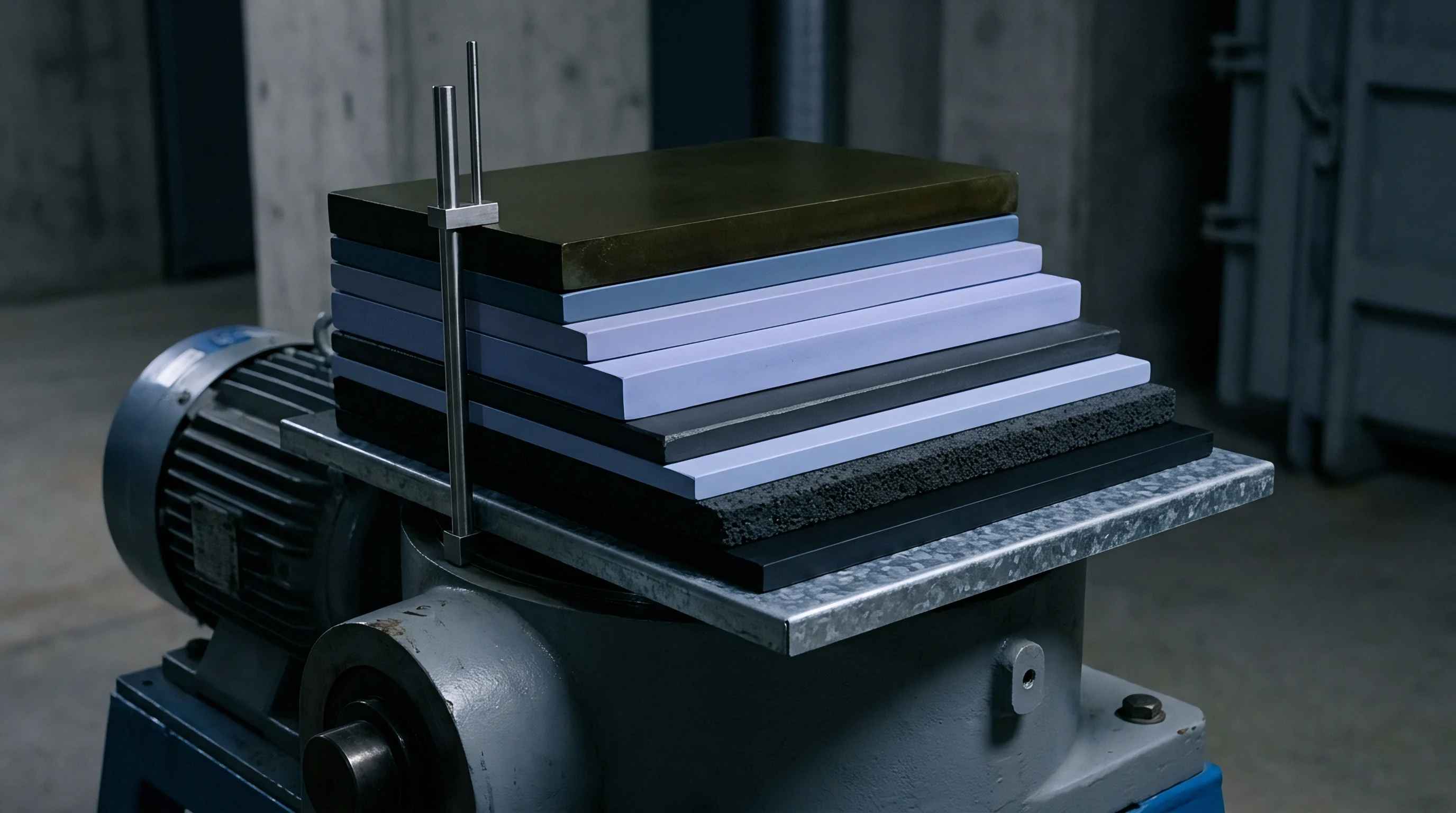
- Determine target compression bounds using stress-strain curves obtained from un-soaked and electrolyte-soaked separator samples under controlled strain rates.
- Evaluate maximum allowable separator thickness loss to ensure total porosity remains above thirty-five percent under end-of-life load conditions.
- Conduct electrochemical impedance spectroscopy across static load increments from fifty to two thousand kilopascals to map the onset of Warburg mass-transfer resistance rise.
- Measure electrolyte displacement volume during initial module clamping to verify peripheral headspace volume accommodates expelled liquid without vent risk.
- Specify constant-force spring elements within module structures to absorb long-term stack expansion without exceeding critical separator yield pressure.
Electrolyte dry-out accelerates chemical aging within active stack regions. Remaining wet channels carry higher current densities, raising local temperatures and accelerating solid electrolyte interphase breakdown. This elevated thermal state degrades liquid lithium hexafluorophosphate salt into fluorinated acid species, prompting transition metal dissolution from the cathode host structure.
Capacity loss under rigid clamping is sometimes attributed to baseline chemical aging rather than separator creep, on the premise that stack compression only optimizes electrical contact while cell degradation follows nominal Arrhenius kinetics.


Plating

Why Does Mechanical Restraint Accelerate Low Temperature Plating?
Low-temperature charging demands rapid ionic diffusion into the host graphite structure to accommodate incoming lithium ions. When static compression reduces electrode porosity and increases electrolyte tortuosity, liquid-phase diffusion slows down considerably. Cold temperatures increase electrolyte viscosity and slow charge-transfer kinetics at the anode surface.
Combined with reduced pore volume under heavy compression, the overpotential required for lithium intercalation pushes past critical thermodynamic thresholds.
Anode potential drops below zero volts relative to metallic lithium whenever local ionic flux outpaces solid-state insertion into graphite. Metallic lithium then nucleates on graphite particle surfaces instead of intercalating into the lattice. Static compressive force changes how this metal deposits: rather than growing as loose dendrites, the plated metal forms dense, planar metallic layers right at the separator-anode interface, physically blocking ionic access to underlying active materials.
| Applied Pressure (kPa) | Separator Thickness Reduction (%) | Low-Temperature Plating Onset (Deg C at 0.5C) | Dominant Degradation Pathway |
|---|---|---|---|
| 100 | 2.1 | -10 | Normal graphite intercalation |
| 300 | 5.4 | -5 | Minor surface lithium deposition |
| 600 | 11.8 | 0 | Localized planar lithium plating |
| 1200 | 22.5 | 5 | Severe pore blockage and fast dead lithium isolation |
Continuous mechanical pressure keeps plated metallic lithium in close contact with surrounding liquid electrolyte. Secondary reactions quickly passivate the plated lithium, turning active metal into inactive electronic dead lithium and lithium compounds. This reaction permanently consumes active lithium inventory, driving sharp, non-linear capacity drops during cycle-life tests under sustained static loads.

Dead Lithium Formation and Anode Creep Mechanics
During discharge, some plated metallic lithium oxidizes back into mobile ions, but isolated metallic pockets lose electrical contact with the graphite matrix. These isolated metallic fragments form dead lithium structures trapped within the interface zone. Heavy mechanical compression flattens these dead lithium deposits into a high-resistance barrier across the anode surface, blocking ionic transport into underlying graphite particles and forcing current density to concentrate elsewhere.
Under IEC 62619 clause 7.2, module assemblies subjected to mechanical compression must prove structural integrity and thermal stability following low-temperature charge protocols without exhibiting internal short-circuits.
Anode creep mechanics cover the long-term plastic deformation of composite electrode materials under constant compressive force. The copper foil, active graphite particles, polymeric binder, and conductive additives rearrange slowly over time under load. Creep reduces overall electrode thickness, altering internal volume ratios and permanently compressing inter-particle void networks.
This creep concentrates structural stress near electrode edges, creating high-risk zones for metallic lithium nucleation during fast charging.
Microstructural analysis confirms these localized creep effects post-cycling.
Scanning electron microscopy of anode surface morphology after five hundred low-temperature cycles under one megapascal compression revealed a continuous three-micrometer dead lithium crust that blocked over forty percent of active graphite surface pores. Electrodes cycled under identical thermal conditions at two hundred kilopascals showed isolated, small-scale metallic deposits, leaving over eighty-five percent of graphite surface pores fully accessible for intercalation.
What structural and mechanical fixture designs can permanently uncouple low-temperature charge acceptance limits from initial pack assembly preloads without adding excessive volume or dead weight to large-scale storage modules?
Fixture

Constant Pressure versus Constant Volume Restraint Jigs
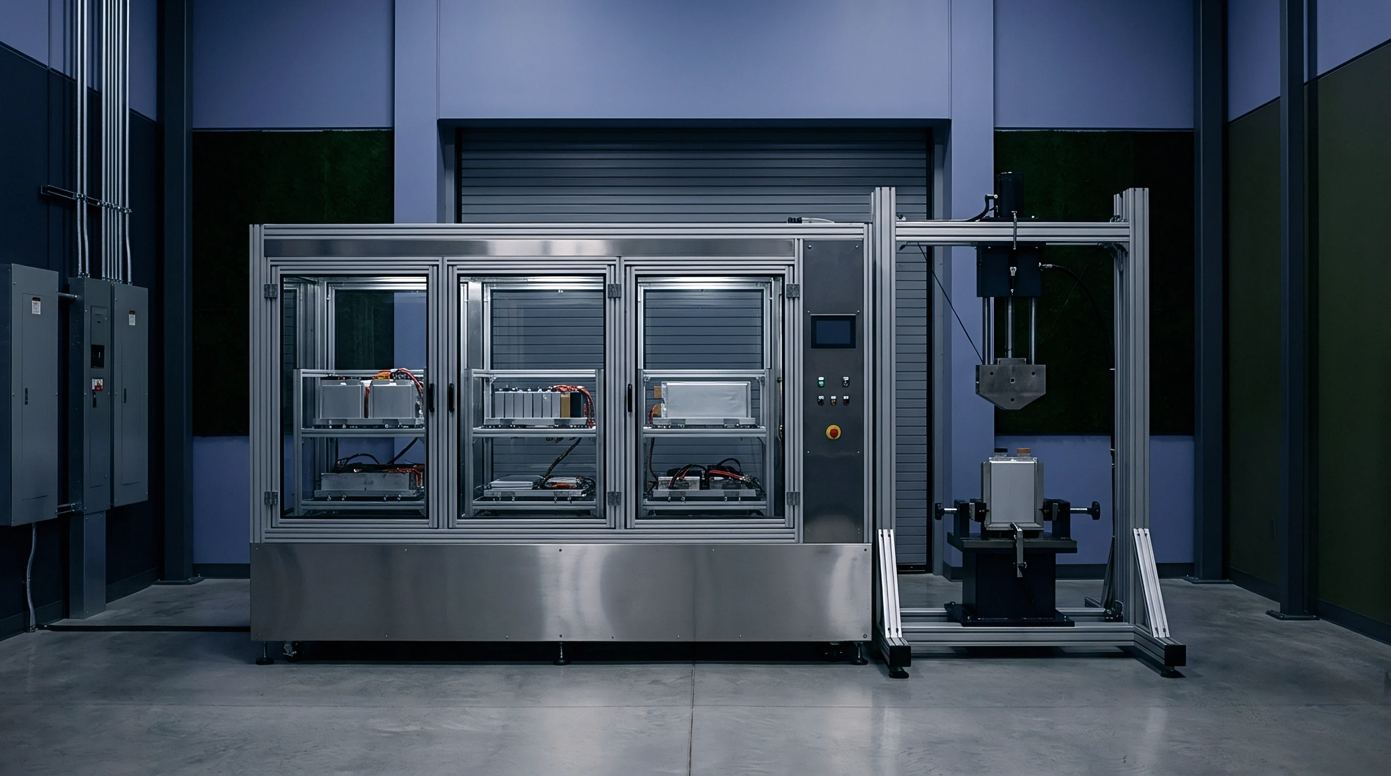
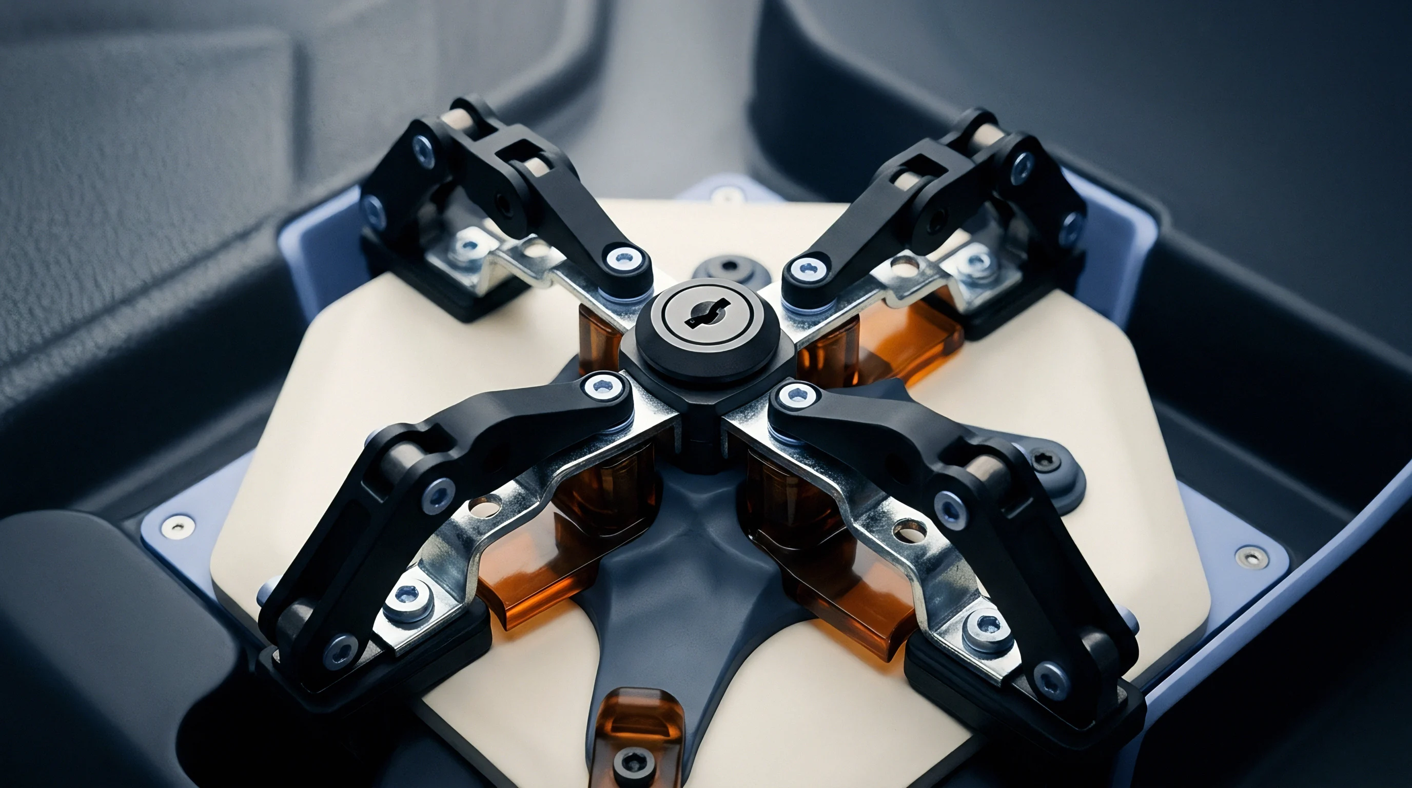
Designing compression fixtures requires choosing between constant-pressure dynamic systems and constant-volume rigid enclosures. Constant-pressure fixtures use compliant spring elements ~ such as Belleville disc washers, coil springs, or elastomeric foam pads ~ to hold a steady compressive force as cell thickness changes. As the cell swells during charging or aging, the compliance mechanism compresses, allowing dimensional growth while keeping applied stress within a narrow band.
Compliant elements damp pressure spikes throughout cell expansion.
Constant-volume fixtures use stiff end-plates linked by rigid tie-rods or structural enclosure walls, locking the outer dimensions of the cell or module. During charge phases and extended aging, internal expansion forces push against immovable boundaries, driving internal stress up non-linearly. A cell assembled with an initial three-hundred-kilopascal static load in a constant-volume fixture can generate internal stress over two megapascals at full state of charge near end of life.
Fixed enclosures constrain outer dimensions at the expense of internal pressure.
Structural integrity depends on the yield limits of enclosure components under peak stress.
Choosing constant-volume systems minimizes pack volume and simplifies mechanics by eliminating bulky springs. However, the non-linear rise in mechanical stress speeds up separator creep, electrolyte expulsion, and particle cracking over time. Constant-pressure systems protect cell internals from excessive peak force, but require dedicated physical volume inside the pack enclosure to accommodate expansion over life.

Thermal Expansion Coupling and Load Cell Drift Calibration
Thermal expansion complicates static compression management in working battery packs. Aluminum, steel, and battery stack materials have vastly different thermal expansion coefficients. Temperature spikes during high-rate discharge cause differential expansion between structural tie-rods and internal electrode stacks.
If tie-rods expand less than the cell stack, mechanical stress surges during high-temperature operation.
| Chemistry and Form Factor | Restraint Architecture | Initial Preload (kPa) | Peak SOC Pressure @ 25°C (kPa) | Peak Thermal Pressure @ 50°C (kPa) |
|---|---|---|---|---|
| NMC Prismatic 120Ah | Rigid Aluminum End-Plates | 300 | 850 | 1420 |
| NMC Prismatic 120Ah | Spring-Loaded Tie Rods | 300 | 340 | 380 |
| LFP Prismatic 280Ah | Rigid Steel Enclosure | 400 | 1150 | 1890 |
| LFP Prismatic 280Ah | Silicone Foam Pad + Rigid Plate | 400 | 580 | 710 |
Interstitial foam dampens short-term thermal expansion surges.
Long-term qualification testing relies on load cells built into test jigs to track stack force evolution. Load cell drift under continuous static load and thermal cycling introduces significant measurement error if left uncorrected. Strain-gauge transducers experience signal creep, zero-point drift, and temperature offsets when held under continuous load for thousands of hours inside environmental chambers.
- Zero the inline load cell sensor at laboratory reference temperature prior to mechanical jig assembly.
- Apply the target static load to the cell stack using a calibrated precision torque wrench or automated hydraulic press.
- Execute thermal pre-conditioning by thermal cycling the empty fixture frame across the operating temperature boundary to quantify frame thermal expansion expansion factors.
- Subtract the frame thermal expansion signal baseline from live test channel load measurements to isolate true internal stack force evolution.
- Perform intermediate recalibration stops during multi-month life tests using calibrated external load frames to correct for transducer offset drift.
Non-compliance with dynamic load management guidelines invalidates battery module warranty coverage under European standard EN 62619 whenever dimensional expansion forces exceed structural limits specified in product technical dossiers.
Under section 8.3 of standard procurement contracts for utility-scale energy storage projects, suppliers must warrant that internal module pressure will not exceed nine hundred kilopascals at end of life when installed inside approved rigid pack structures, shifting the financial risk of frame deformation and accelerated cell fade directly to the cell manufacturer.

Dossier

Regulatory Proof Chains for Compressed Pack Modules
Certifying compressed battery modules for cross-border transport and commercial deployment requires complete traceability between laboratory compression data and factory assembly lines. Standard UN 38.3 certification packages require modules to pass thermal, shock, and vibration testing at maximum specified mechanical restraint conditions. Modifying clamping specs, fastener torques, or foam padding after certification invalidates existing safety summaries and shipping approvals.
Regulatory approvals demand documented, continuous empirical compliance.
Transport authorities evaluate module structural integrity through vibration testing (UN 38.3 Test 3) and mechanical shock testing (UN 38.3 Test 4). If static preload drops over time from plastic creep or foam pad compression, individual cells can shift laterally during transport vibration. Mechanical fretting of cell casing insulation against structural frame walls then increases the risk of internal ground faults and short circuits.
Proving compliance requires test records showing that internal stack preloads remain within safe operational bounds under all environmental conditions. Mechanical test summaries must document initial torque limits, compression pad material formulations, load displacement curves, and environmental test history. Technical dossiers lacking clearly defined compression parameters face rejection during carrier acceptance reviews and dangerous goods audits.

UN Three Eight Point Three Impact and EU Battery Regulation Compliance
The European Union Battery Regulation 2023/1542 introduces mandatory performance, durability, and safety rules that link mechanical cell restraint protocols directly to supply chain compliance. Annex VI requires technical documentation to explicitly list mechanical design parameters, including initial compressive force, long-term stress relaxation profiles, and maximum swelling allowances over cycle life. Omitting verified compression limits prevents cell and pack products from receiving the CE mark needed for European market entry.
A verified compliance file must contain original test summaries demonstrating that mechanical module structures withstand maximum swelling forces generated during extended cycle testing without frame structural yield or venting.
The regulatory file serves as a legally binding bridge connecting the physical assembly line to safety declarations. Any structural change to module end-plates, tie-rod dimensions, or internal spring elements requires re-evaluating certified shipping files. Retaining detailed compliance records ensures regulatory clearance remains valid throughout the commercial lifecycle of the battery pack.
- Initial mechanical preload specification document detailing maximum, nominal, and minimum permissible clamping forces applied during module integration.
- UN 38.3 test summary revision sheet explicitly matching the mechanical fixture state used during certified vibration and shock testing protocols.
- Compressive stress relaxation profile data for all internal elastomeric foam pads across expected operating thermal ranges over ten years.
- End-of-Life swelling force projection report generated via accelerated cycling tests executed under constant-volume structural boundary conditions.
- Material compliance certificates proving structural end-plates and tie-rods retain yield strength requirements under continuous static stress.
Every shipment of dangerous goods requires full regulatory alignment. An incomplete safety file leaves cargo stranded at port facilities, driving up demurrage costs and line disruption penalties. Sourcing teams should audit supplier compression test files before issuing purchase orders for cells intended for international pack integration.