Continuous Graphitization Scale Bottlenecks and Industrial Hard Carbon Pre-Sodiation Yield Economics
Continuous hard carbon graphitization requires tight thermal control to preserve closed nano-cavities, while pre-sodiation economics rely on holding web yield above 96 percent.
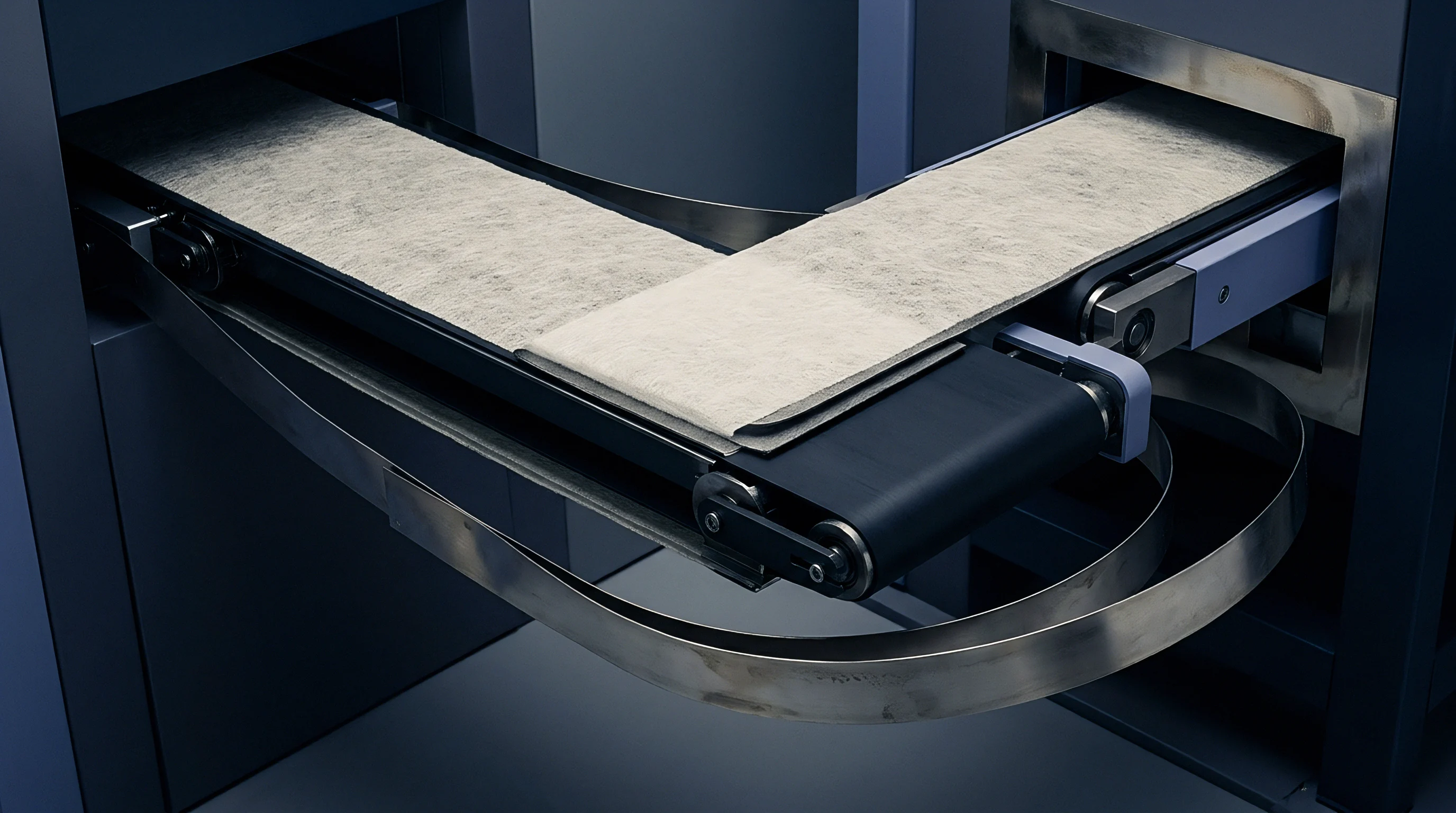
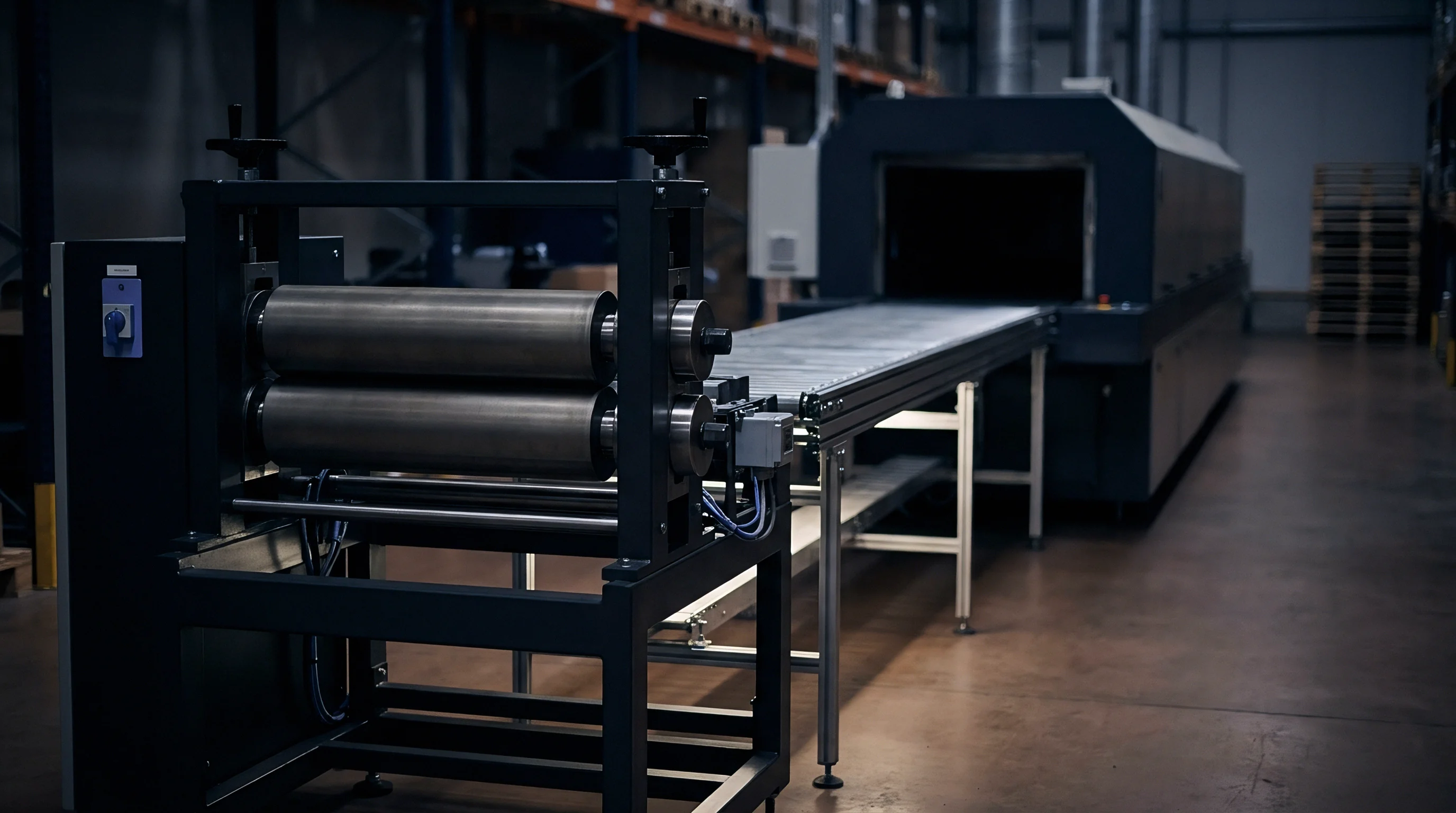
Kiln
Thermal processing of precursor carbons sets the fundamental boundary for sodium-ion battery anode production. While natural graphite anodes require flake purification and spherical shaping followed by heat treatment above 2800 degrees Celsius, hard carbon synthesis operates much lower, between 1000 degrees Celsius and 1400 degrees Celsius. In this lower window, non-graphitizable carbons derived from biomass, phenolic resins, sucrose, or coal tar pitch undergo pyrolytic decomposition and structural rearrangement.
Rather than long-range crystalline order, the target is a turbostratic structure: short-range, disordered graphene domains punctuated by nano-cavities and wide interlayer spacings. Producing this precise microstructural geometry at commercial volumes creates severe engineering bottlenecks when shifting from static batch retorts to continuous high-throughput systems.
Batch pyrolysis retorts offer uniform residence times and steady atmospheric control, but throughput stays limited by thermal mass and long heating cycles. Continuous rotary kilns and indirect-fired electric tunnel kilns move far more material, but introduce steep thermal and chemical gradients. As precursor tumbles through a continuous rotary kiln, volatile organic compounds evolve rapidly during primary carbonization between 400 degrees Celsius and 700 degrees Celsius.
If high-velocity counter-current inert gas purges do not sweep these outgassed tars and light hydrocarbons away immediately, they crack on the surfaces of adjacent carbon particles. This secondary deposition seals open pores, forms dense crystalline shells, and alters local carbon chemistry.
In continuous shaft and rotary furnaces, thermal symmetry across the bed cross-section is notoriously hard to maintain. Material tumbling near the heated refractory wall sees higher peak temperatures and faster heating rates than material in the core. A temperature variance of just 45 degrees Celsius across the bed alters the ratio of graphitic domains to disordered aliphatic chains.
Higher local temperatures cause microstructural shrinkage, pulling the average inter-graphene layer spacing below 0.37 nanometers. Below this threshold, sodium ion transport kinetics drop sharply, triggering localized sodium plating during high-rate charging.
Rotary furnace carbonization at 1300 degrees Celsius under high-purity argon yields an initial coulombic efficiency of 84.2 percent when tested against metallic sodium between 0.001 and 2.0 volts at 0.1C rate.
Atmospheric purity in continuous kilns is another critical failure point. Oxygen ingress above 15 parts per million at carbonization temperatures over 1000 degrees Celsius causes active surface etching. This oxidative attack increases the specific surface area measured by nitrogen Brunauer-Emmett-Teller gas adsorption, expanding the fraction of open micropores.
A high specific surface area degrades first-cycle efficiency by consuming active sodium ions during initial Solid Electrolyte Interphase formation. Continuous processing systems must balance positive-pressure argon locks against the high gas extraction velocities needed to clear heavy tar volatiles without pulling air through dynamic end seals. Mechanical seal wear under thermal cycling creates chronic air leaks that can corrupt entire production runs.
Continuous processing also encounters bottlenecks during the final high-temperature soaking phase. Hard carbon requires precise residence time at peak temperature so cross-linked hydrocarbon chains can reorganize into curved graphene sheets without crystallizing into dense graphite. In batch furnaces, six to twelve hour soak times are standard.
Continuous tunnel kilns can only match that residence time with excessively long heating zones or reduced feed rates, undermining capital efficiency. Speeding up material feed through a rotary or tunnel kiln cuts the soak short, leaving un-crosslinked amorphous carbon regions that collapse during early cycling.
| Process Parameter | Continuous Rotary Kiln | Indirect Electric Tunnel Kiln | Stationary Batch Retort |
|---|---|---|---|
| Peak Temperature Range (°C) | 1100 to 1350 | 1150 to 1400 | 1000 to 1300 |
| Temperature Uniformity across Bed (°C) | ±35 to ±50 | ±15 to ±25 | ±5 to ±10 |
| Residence Time at Peak Temperature (hr) | 0.75 to 2.5 | 2.0 to 5.0 | 6.0 to 12.0 |
| Specific Gas Purging Volumetric Flow (m³/kg precursor) | 4.2 to 6.8 | 2.5 to 4.0 | 1.2 to 1.8 |
| Specific Surface Area Variance (BET N₂ m²/g) | ±2.8 | ±1.2 | ±0.4 |
| Capital Expenditure per Annual Ton ($/ton capacity) | 1200 to 1600 | 2200 to 2800 | 800 to 1100 |
Hard carbon precursor economics depend on balancing volatile loss against total electric furnace duty. Biomass precursors like coconut shell or shaddock peel lose up to 65 percent of their dry mass as condensable tars and non-condensable gases during primary carbonization. Pitch and synthetic resin precursors offer higher carbon yields, typically between 45 percent and 60 percent, but produce sticky, viscous volatiles that foul exhaust manifolds.
Tar buildup inside ductwork changes system backpressure, shifting gas flow dynamics and allowing localized oxygen back-diffusion. Cleaning these continuous flue systems requires periodic thermal burn-offs or mechanical scraping shutdowns, dropping actual plant availability from a target of 92 percent down to under 78 percent annually.
Volatile tar condensation inside continuous exhaust flues drives batch-to-batch graphitic alignment shifts during high-throughput carbonization runs.

Pores
Turbostratic domain structure determines how sodium ions intercalate within non-graphitizable carbon networks. Unlike lithium, which intercalates between graphitic sheets to form a stage-one LiC6 compound with a theoretical capacity of 372 milliampere-hours per gram, sodium’s larger ionic radius prevents equivalent staging in narrow channels. Hard carbon stores sodium through a two-step mechanism: a sloping voltage region above 0.1 volts versus sodium metal, corresponding to intercalation between disordered graphene layers and adsorption at defects, followed by a flat voltage plateau below 0.1 volts as sodium condenses into closed nano-cavities.
Controlling the ratio of open surface pores to internal closed cavities dictates the commercial value of the material.
Open micropores under two nanometers that reach the particle surface carry an electrochemical penalty. During initial charging, liquid electrolyte enters these channels and contacts active carbon surfaces. The reductive decomposition of sodium salts ~ like sodium hexafluorophosphate (NaPF6) or sodium bis(fluorosulfonyl)imide (NaFSI) ~ and alkyl carbonate solvents forms the Solid Electrolyte Interphase layer inside these micro-channels.
Because internal surface area in open micropores is vast, SEI growth consumes a massive amount of sodium from the cathode. This irreversible loss shows up directly as an Initial Coulombic Efficiency deficit, often dropping un-presodiated hard carbon first-cycle efficiency to between 70 percent and 82 percent.
Irreversible sodium loss happens through both electrolyte decomposition and physical trapping at defect sites. Oxygen functional groups ~ carboxyl, carbonyl, and hydroxyl groups left on the surface after low-temperature pyrolysis ~ react irreversibly with sodium to form stable carboxylates and oxides. Residual hydrogen also drives non-recyclable sodium loss.
When carbonization stays below 1100 degrees Celsius, residual aliphatic hydrogen bonds weaken local electronic conductivity and trap sodium inside lattice distortions. Heating to 1300 degrees Celsius strips out residual hydrogen and oxygen heteratoms, but excessive temperatures collapse the internal closed nano-cavities required for high plateau capacity.
Synthesizing hard carbon with optimized nano-cavities requires strict control over precursor cross-linking density before carbonization. Thermosetting polymers or pre-oxidized pitch form rigid three-dimensional networks that resist graphitization even at 1400 degrees Celsius. As volatiles escape these networks, they leave behind isolated void volumes bounded by curved, few-layer graphene sheets.
These closed pores must stay inaccessible to liquid electrolyte while remaining open to sodium ions through narrow defect channels. If entrance channels are too wide, electrolyte molecules enter, decompose, and clog the cavity, making the internal volume electrochemically dead.
The list below outlines primary structural breakdown mechanisms that degrade hard carbon performance in sodium-ion applications.
- Open Micropore Exfoliation occurs when solvent molecules co-intercalate with sodium ions into unsealed surface channels, causing localized structural swelling and continuous SEI re-growth.
- Defect-Site Trapping immobilizes sodium ions via irreversible chemical bonding with residual oxygen and hydrogen surface functional groups left after incomplete pyrolysis.
- Cavity Collapse reduces total flat-plateau sodium storage capacity when continuous thermal processing exceeds maximum allowable soak temperatures, converting void volumes into dense graphitic stacks.
- Interlayer Contraction restricts sodium ion diffusion kinetics when graphitization proceeds too far, narrowing average d002 spacing below the critical 0.37 nanometer threshold required for low-voltage plateau transport.
Characterizing hard carbon porosity requires complementary gas adsorption techniques. Standard nitrogen BET analysis measures surface area down to micropores around 0.35 nanometers, but nitrogen struggles to diffuse into narrow pore entrances at 77 Kelvin. Carbon dioxide adsorption at 273 Kelvin probes ultra-fine micropores down to 0.3 nanometers due to higher thermal kinetic energy and gas pressure.
Small-Angle X-ray Scattering provides the true metric for internal closed pore volume, detecting isolated nano-cavities completely sealed from gas ingress. A high-performing hard carbon anode exhibits a nitrogen surface area below 3.0 square meters per gram alongside a SAXS closed pore volume exceeding 0.08 cubic centimeters per gram.
| Microstructural Parameter | Low-Temperature Pyrolysis (1000°C) | Optimized Hard Carbon (1300°C) | Over-Graphitized Carbon (1600°C) |
|---|---|---|---|
| Interlayer Spacing d₀₀₂ (nm) | 0.395 to 0.410 | 0.372 to 0.385 | 0.345 to 0.358 |
| BET Nitrogen Surface Area (m²/g) | 12.5 to 28.0 | 1.1 to 2.8 | 0.5 to 1.2 |
| CO₂ Ultrafine Micropore Volume (cm³/g) | 0.085 to 0.120 | 0.035 to 0.055 | 0.005 to 0.012 |
| SAXS Closed Pore Volume (cm³/g) | 0.020 to 0.040 | 0.075 to 0.105 | 0.015 to 0.030 |
| Reversible Capacity (mAh/g) | 240 to 280 | 310 to 355 | 180 to 220 |
| Initial Coulombic Efficiency (%) | 68.0 to 76.0 | 85.0 to 89.5 | 91.0 to 94.0 |
Particle morphology is another key variable in continuous carbon synthesis. Spherical or rounded particles pack tighter than irregular flakes, raising electrode tap density from 0.5 grams per cubic centimeter to over 0.9 grams per cubic centimeter. Higher tap density reduces inter-particle void space in the calendared coating, lowering the volume of electrolyte needed to wet the anode.
Since sodium-ion electrolyte relies on expensive salts like NaPF6 or NaFSI dissolved in carbonate mixtures, cutting fill volume directly lowers pack cost. Irregular, low-density particles absorb too much electrolyte, leaving dry spots that accelerate capacity fade during fast charging.
When processing hard carbon with high surface defect counts, water-soluble binders like carboxymethyl cellulose react aggressively with acidic surface groups. This causes premature binder gelation in mixing tanks, forcing coating lines to run at lower solids loading. Lower solids loading increases energy demand in drying ovens on roll-to-roll coaters, cutting web speeds from 60 meters per minute down to 35 meters per minute.
Thermal pyrolysis conditions, pore morphology, and downstream coating speed are tightly linked ~ anode material yield cannot be evaluated without considering cell assembly economics.
Higher carbonization temperatures decrease open surface area while expanding closed void volume, shifting storage from surface reaction to cavity filling.
Micropore volume measured by nitrogen gas adsorption correlates directly with first-cycle capacity loss during formation.
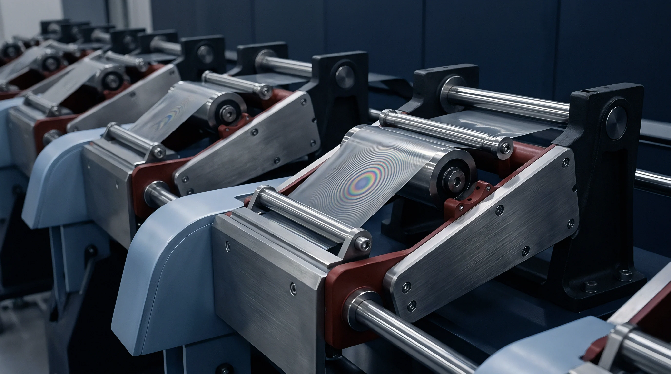

Reagent
Adding sodium ions before cell sealing offsets the initial coulombic deficit. Because low first-cycle efficiency in hard carbon anodes permanently sequesters sodium from the cathode, the finished cell loses discharge capacity and energy density. To prevent cathode de-sodiation from starving the cell, pre-sodiation introduces auxiliary sodium before or during early formation cycling.
Industrial methods fall into two main categories: chemical or electrochemical pre-treatment of the anode web before assembly, or adding sacrificial sodium compounds directly to the cathode formulation.
Sacrificial cathode additives are the simplest mechanical option for high-volume manufacturing. Compounds like sodium oxide (Na2O), sodium oxalate (Na2C2O4), sodium azide (NaN3), and squarate salts (Na2C4O4) are mixed into the cathode slurry alongside active materials like layered transition metal oxides or sodium vanadium phosphate (Na3V2(PO4)3). On the first charge cycle, these additives decompose electrochemically at specific voltages, releasing sodium ions that migrate across the separator to form the SEI layer and fill traps on the anode.
Non-metallic residual byproducts remain in the cathode or evolve into gas that must be vented before final sealing.
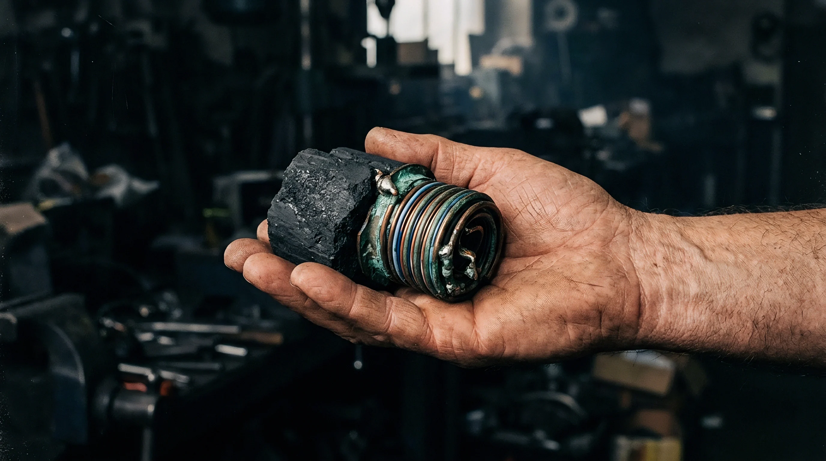
Does Chemical Pre-Sodiation Scale outside Dry Rooms?
Pre-sodiation in chemical solution baths works quite differently. Hard carbon electrode rolls pass through a bath of organometallic sodium complexes dissolved in ether solvents ~ like sodium naphthalenide or sodium biphenyl in tetrahydrofuran or dimethoxyethane. The chemical potential of the sodium complex is high enough to spontaneously transfer electron-sodium ion pairs into the hard carbon, pre-charging the anode without an external circuit.
Speeds in roll-to-roll immersion tanks depend on reaction kinetics and ion diffusion rates into the porous web. Bath residence times usually range from 30 seconds to 3 minutes, requiring long dip tanks built into continuous coating lines.
Tetrahydrofuran reacts quickly, but its high vapor pressure and low flash point create severe fire hazards and heavy solvent recovery expenses inside industrial coating enclosures. Dimethoxyethane is less volatile, but higher viscosity slows the diffusion of sodium-solvate complexes into dense, calendared coatings. Residual organometallic complexes left in electrode pores must also be washed out in secondary baths.
Unwashed naphthalene or biphenyl molecules decompose at high voltages during cycling, releasing gas and destabilizing the cathode-electrolyte interphase.
| Pre-Sodiation Methodology | Sodium Supply Mass Efficiency (%) | Processing Atmosphere Requirement | Gas Generation Penalty | Estimated Additive/Reagent Cost ($/kWh) |
|---|---|---|---|---|
| Sacrificial Oxalate (Na₂C₂O₄) | 35.8 | Standard Dry Room (Dew Point -40°C) | High (CO₂ gas release) | 3.50 to 5.20 |
| Sacrificial Oxide (Na₂O) | 74.2 | Ultra-Dry Room (Dew Point -65°C) | None (Solid residue) | 8.00 to 14.00 |
| Chemical Bath (Na-Naphthalenide/DME) | 88.0 (reagent basis) | Inert Glovebox/Enclosure (Ar/N₂) | None (Pre-assembly) | 6.20 to 11.50 |
| Electrochemical Roll-to-Roll Dip | 96.5 | Ultra-Dry Argon Atmosphere | None (Pre-assembly) | 12.00 to 18.50 |
| Stabilized Sodium Metal Powder (SSMP) | 98.0 | Ultra-Dry Room (Dew Point -55°C) | None (Direct intercalation) | 15.00 to 22.00 |
Applying Stabilized Sodium Metal Powder directly onto the hard carbon surface avoids liquid chemical baths. SSMP particles carry a thin protective coating of sodium carbonate or inorganic salts, allowing handling in dry rooms with dew points below -55 degrees Celsius. During calendaring or electrolyte injection, mechanical pressure and liquid solvent break the protective shell, allowing metallic sodium to react with the carbon particles.
Distributing sodium powder evenly across wide electrode webs running at 50 meters per minute remains an open mechanical problem. Local concentrations of powder create hot spots that form metallic sodium dendrites, causing micro-shorts through thin polyolefin separators.
Electrochemical roll-to-roll pre-sodiation offers the highest precision, but requires massive capital investment. Here, the hard carbon web acts as a continuous working electrode moving through an electrolyte bath opposite a counter-electrode of metallic sodium or a sodium-intercalated source material. An external power supply drives a controlled current, injecting an exact amount of sodium into the web.
Current density must adjust dynamically with line speed and web tension to prevent metallic sodium plating where the web enters the bath. Capital expenses for continuous electrochemical lines with automated sodium wire feeding often exceed 15 million dollars per GWh of annual capacity.
Compliance with UN 38.3 transport testing for cells containing chemically pre-sodiated anodes mandates thermal stability testing at 72 degrees Celsius for six continuous hours without voltage loss.
Sacrificial cathode additives simplify web handling, though they shift the operational burden onto formation gas venting.
The exact threshold at which residual organic solvents from chemical bath immersion accelerate electrolyte degradation over two thousand cycles remains unquantified across commercial supply chains.
Scrap
Yield losses during web conversion and cell formation add directly to the bill of materials on sodium-ion manufacturing lines. Pre-sodiated hard carbon electrodes react aggressively with ambient moisture and oxygen. While standard graphite anode webs can sit in buffer racks inside standard dry rooms for days without degrading, pre-sodiated webs oxidize immediately if moisture fluctuates.
Water vapor converts active intercalated sodium into sodium hydroxide (NaOH) and hydrogen gas (H2). Sodium hydroxide then attacks vinylidene fluoride binders, causing cross-linking, dehydrofluorination, and severe embrittlement that triggers web tears during slitting and winding.
Process lines with pre-sodiation must operate in ultra-dry enclosures with dew points strictly below -55 degrees Celsius ~ less than 0.015 grams of water vapor per kilogram of dry air. Maintaining these conditions across slitting, stacking, and pouch insertion zones increases dry room HVAC energy consumption by up to 40 percent compared to standard lithium-ion assembly. If an HVAC compressor trips or dry room moisture spikes to -35 degrees Celsius for even ten minutes, the surface layer of pre-sodiated rolls oxidizes, spoiling the pre-charge stoichiometry and turning entire 1000-meter electrode rolls into scrap.
The sequence below details the mandatory inspection steps for incoming pre-sodiated hard carbon webs during high-speed cell manufacturing.
- Sample three 100-square-millimeter coupons from the outer wrap, middle core, and inner core of each slit electrode roll under argon atmosphere.
- Transfer coupons directly into a sealed glovebox titrator to quantify unreacted surface sodium hydroxide via non-aqueous acid-base titration.
- Measure cross-sectional electrical conductivity using a four-point inline probe to detect localized oxidation zones across the web width.
- Verify coat weight uniformity using a beta-ray mass gauge linked to continuous web tension load cells to prevent mechanical stretch distortion.
- Run differential scanning calorimetry on active material scraped from sample coupons to verify thermal stability threshold stays above 140 degrees Celsius in standard electrolyte.
Web handling machinery must be modified to prevent micro-fracturing of pre-sodiated coatings. Pre-sodiation makes the active carbon layer significantly stiffer and more brittle. Passing over small-radius turn-bars and dancer rolls in automated assembly gear puts severe shear stress on the brittle coating, delaminating active carbon from the aluminum foil current collector.
Unlike lithium-ion cells that require copper anode collectors, sodium-ion cells use aluminum on the anode side because sodium does not alloy with aluminum at low potentials. However, aluminum foil is thinner and far less tolerant of tension variations than copper, raising line-breakage scrap rates during high-speed winding.
Pre-sodiation selection involves critical operational balances across safety, yield, and machinery integration options.
- Sacrificial Additive Integration simplifies web mechanics but forces extended vacuum degas holding periods to remove high volumes of evolved carbon dioxide gas.
- Chemical Bath Pre-Sodiation maximizes initial coulombic yield but demands expensive explosion-proof continuous drying enclosures and complex solvent recycling loops.
- Direct Powder Application minimizes chemical handling overhead but introduces chronic risks of separator puncture from non-uniform metallic powder agglomerates.
- Electrochemical Web Dip provides precise voltage target control but restricts line conversion speeds due to limited bath current transfer density boundaries.
Degassing steps during cell formation present another yield hurdle. When using sacrificial cathode additives like sodium oxalate, the first charge cycle releases large volumes of carbon dioxide inside the sealed pouch cell. To accommodate this, cells are built with an extra gas pocket along one side.
Formation requires transferring the cell to a vacuum sealing station, piercing the pocket under deep vacuum, evacuating the gas, and making a second seal below the pocket before trimming the bag as scrap. Handling steps for gas bag removal double the floor space required for formation and introduce leak risks along the secondary seal.
Atmospheric moisture exposure exceeding five minutes inside a standard dry room oxidizes active pre-sodiated surfaces and negates first-cycle efficiency gains.
Ambient dew point fluctuations trigger micro-gassing during final degas sealing, forcing pouch cell write-offs on the formation line.

Ledger
Financial viability for commercial sodium-ion cells hinges on balancing material synthesis yields against cell-level energy density. Hard carbon synthesis cost varies wildly based on precursor selection and thermal carbonization efficiency. Low-cost agricultural waste like coconut shell carries raw material prices below 0.80 per kilogram, but yields inconsistent microstructural parameters that demand high-temperature gas purges and extensive magnetic iron decontamination.
Synthetic precursors like phenolic resins or refined coal tar pitch cost between $2.50 and $4.50 per kilogram, yielding uniform carbon structures with lower surface defect rates. Factoring in volatile mass loss during pyrolysis, electric furnace power consumption, and continuous rotary kiln maintenance, un-presodiated hard carbon anode material lands at a production cost of $4.20 to $7.80 per kilogram.
Capital expenditure for continuous high-temperature graphitization kilns dominates the baseline cost structure of hard carbon plants. A continuous electric tunnel kiln designed to produce 5,000 annual metric tons of battery-grade hard carbon requires an initial capital outlay of approximately 14 million dollars. Operating this equipment under continuous high-purity argon flow adds $0.65 per kilogram in inert gas consumption alone.
If kiln throughput is reduced by 25 percent to extend residence time for optimal closed nano-cavity development, fixed capital depreciation per kilogram rises proportionally, undermining the cost advantage that sodium-ion technology holds over low-cost lithium iron phosphate ($LiFePO4) chemistries.
The financial ledger shifts dramatically when pre-sodiation is integrated into the manufacturing chain. Sacrificial cathode additives such as sodium oxalate add $0.40 to $0.85 to the raw material bill of materials cost per kilowatt-hour of finished cell capacity. Chemical pre-sodiation baths using sodium naphthalenide add $2.20 to $4.10 per kilowatt-hour when accounting for reagent consumption, organometallic solvent loss, and capital equipment depreciation for dry-room chemical enclosures.
However, by recovering the 12 to 18 percent of active sodium ions lost during initial SEI formation, pre-sodiation increases the net cell-level discharge capacity, effectively reducing the landed cost per delivered watt-hour of active cell stack volume.
| Anode & Process Configuration | Hard Carbon Synthesis Cost ($/kg) | Pre-Sodiation Add-on Cost ($/kWh) | Cell Energy Density (Wh/kg) | Cycle Life to 80% SOH (0.5C/0.5C) | Landed Cell Cost ($/kWh delivered) |
|---|---|---|---|---|---|
| Un-presodiated Bio-Carbon (Low ICE: 74%) | 4.20 | 0.00 | 125 | 1400 | 62.50 |
| Un-presodiated Synthetic Carbon (Med ICE: 84%) | 7.50 | 0.00 | 142 | 2200 | 58.80 |
| Bio-Carbon + Sacrificial Oxalate Additive | 4.20 | 1.85 | 148 | 2800 | 51.20 |
| Synthetic Carbon + Chemical Bath Pre-Sodiation | 7.50 | 3.40 | 165 | 4500 | 46.90 |
| Synthetic Carbon + Electrochemical Roll Dip | 7.50 | 5.80 | 168 | 5200 | 49.30 |
Consider a post-mortem financial case of a 1.2 GWh sodium-ion cell plant converting its production lines from un-presodiated hard carbon to a chemical bath pre-sodiation system. In the un-presodiated baseline configuration using medium-grade synthetic hard carbon with an Initial Coulombic Efficiency of 84 percent, the cell achieves a volumetric energy density of 290 Watt-hours per liter and a gravimetric energy density of 142 Watt-hours per kilogram. Landed cell manufacturing cost stands at $58.80 per kilowatt-hour.
Introducing chemical bath pre-sodiation adds 4.2 million dollars in continuous dip-tank machinery and boosts annual dry room operational expenses by $380,000. Reagent consumption adds $3.40 per kilowatt-hour directly to the active bill of materials.
Despite these added operating and capital costs, pre-sodiation increases the usable cell energy density to 165 Watt-hours per kilogram by eliminating the cathode capacity penalty. Because fewer total cells, less housing metal, and less liquid electrolyte are required to build a battery module of equivalent energy capacity, the module-level assembly cost drops. Crucially, pre-sodiation offsets continuous active sodium consumption over long-term cycling, extending cycle life from 2,200 cycles to 4,500 cycles at 80 percent State of Health under 0.5C charge and discharge conditions at 25 degrees Celsius.
Amortizing the total cell and pack cost over the extended cycle life reduces the levelized cost of energy storage from $0.0267 per kilowatt-hour per cycle down to $0.0104 per kilowatt-hour per cycle.
Yield loss spikes during pre-sodiation can completely erode these calculated levelized cost benefits. If web handling breakages, binder degradation, and dry-room humidity trips push cell scrap rates from a baseline of 3.5 percent up to 12.8 percent, the effective landed cell cost jumps to $64.10 per kilowatt-hour. The financial viability of pre-sodiation depends entirely on holding continuous web processing yield above 96 percent.
Cell manufacturers must continuously audit material supplier lot-to-lot consistency, enforcing tight tolerances on hard carbon specific surface area, moisture content, and particle sizing before releasing materials into the continuous pyrolysis and pre-sodiation streams.
Supply contracts incorporating strict lot-acceptance criteria based on differential capacity profile variance force vendors to absorb material replacement costs for un-presodiated batch shifts.