Solid-State Electrolyte Interface Impedance Evolution and Current Maldistribution under Transient Thermal Gradients in Parallel Modules
Thermal gradients across parallel solid-state cells skew branch impedance exponentially, concentrating high current into warmer cells and triggering local shorts.
Kinetics
A potentiostat channel logs a baseline area-specific resistance of 28.4 ohm square centimeters on an uncycled lithium phosphorus sulfur chloride pouch cell held at 25 degrees Celsius under 5.0 megapascals of uniaxial pressure. When a 100-ampere discharge pulse hits a four-cell parallel group, heat dissipation across the central cooling plate lags heat generation inside the inner cores. The core of cell two climbs to 38 degrees Celsius within ninety seconds, while cell four remains at 26 degrees Celsius against the outer module chassis.
That twelve-degree span cuts the charge-transfer resistance of cell two by more than half: the ion-hopping barrier across the solid electrolyte interface follows Arrhenius kinetics with an activation energy between 0.32 and 0.45 electron-volts.
While bulk separator ionic conductivity stays relatively stable across modest temperature shifts, the solid-solid boundary between the metallic lithium anode and the ceramic or glass-ceramic electrolyte is far more thermally sensitive. Liquid electrolytes use pore wetting and convection to soften local flux spikes, but solid-state transport runs strictly through fixed lattice positions and physical micro-contacts. As local temperature rises, ion transfer across the solid-electrolyte interphase accelerates, lowering interfacial impedance much faster than bulk ionic or electronic pathways can balance.
A temperature rise from 25 to 40 degrees Celsius drops sulfide electrolyte interface impedance by 54 percent under continuous 5 megapascal constraint.
Charge-transfer resistance at the solid interface sits in series with bulk electrolyte resistance and the constriction resistance caused by incomplete interfacial contact. Because parallel cells on a shared copper busbar share an identical terminal voltage by Kirchhoff’s laws, any local temperature rise in one cell drives its total branch resistance down. The resulting impedance drop routes disproportionate current into that warmer cell, feeding an asymmetric current partition that accelerates local Joule heating.

Arrhenius Sensitivity across Solid Interfaces
Thermal activation governs exchange current density across solid electrochemical junctions under Butler-Volmer kinetics. Interface resistance scales inversely with exchange current density, which depends exponentially on activation energy over the gas constant and absolute temperature. Sulfide solid electrolytes like lithium phosphorus sulfur chloride and lithium germanium phosphorus sulfur compounds exhibit interfacial charge-transfer activation energies between 30 and 42 kilojoules per mole.
Oxide systems such as doped lithium lanthanum zirconium oxide impose higher barriers, typically between 50 and 68 kilojoules per mole.
Those higher activation barriers sharpen current divergence across parallel branches during thermal transients. A five-degree delta in an oxide module alters interface impedance far more sharply than the same delta would in a sulfide pack. Without capillary action to redistribute electrolyte, thermal gradients lock in persistent current density variations across the electrode area.
Kinetic and transport values for representative solid-state systems under standardized compression appear below.
| Electrolyte System | Bulk Conductivity at 25C (mS/cm) | Interfacial ASR at 25C (ohm cm²) | Interfacial ASR at 45C (ohm cm²) | Interfacial Activation Energy (eV) | Critical Current Density at 25C (mA/cm²) |
|---|---|---|---|---|---|
| Li6PS5Cl (Argyrodite) | 2.8 | 24.5 | 10.8 | 0.36 | 1.8 |
| Li10GeP2S12 (Thio-LISICON) | 9.5 | 42.0 | 16.5 | 0.41 | 1.2 |
| Li6.4La3Zr1.4Ta0.6O12 (LLZTO) | 0.9 | 115.0 | 31.2 | 0.58 | 0.7 |
| PEO-LiTFSI Composite (Dry Polymer) | 0.08 | 340.0 | 68.0 | 0.72 | 0.3 |
These values derive from symmetric cell impedance spectroscopy published between 2022 and 2024 for coin and small pouch formats under five megapascals of mechanical load. If stack compression drops from 5.0 megapascals to 0.5 megapascals, baseline area-specific resistance at 25 degrees Celsius roughly doubles or triples as microscopic contact points separate, shifting the governing impedance from charge-transfer kinetics toward constriction resistance. Cell specifications from early pilot lines require close attention to this mechanical coupling during thermal swings.
Charge Transfer Inhomogeneity under Heat Steps
Transient loads generate steep thermal fields well before cold plates or liquid coolant loops reach steady-state heat rejection. During fast charging from a 20 degrees Celsius soak, internal core-to-surface gradients in prismatic solid-state cells can exceed 0.8 degrees Celsius per millimeter of stack thickness. Layers adjacent to internal current collectors heat first, dropping local charge-transfer resistance while peripheral material stays cold and resistive.
When current channels through hot zones, local current density can easily outstrip the critical current density limit of the solid electrolyte. On metallic lithium anodes, exceeding critical current density during stripping nucleates interfacial voids that reduce actual contact area. On subsequent charges, current concentrates into whatever contact area remains, multiplying local flux and driving dendrites through grain boundaries in the ceramic separator.
Early test channel short circuits frequently stem from transient thermal divergence and localized interface breakdown rather than particulate contamination during dry-room pouch assembly.
Clamp
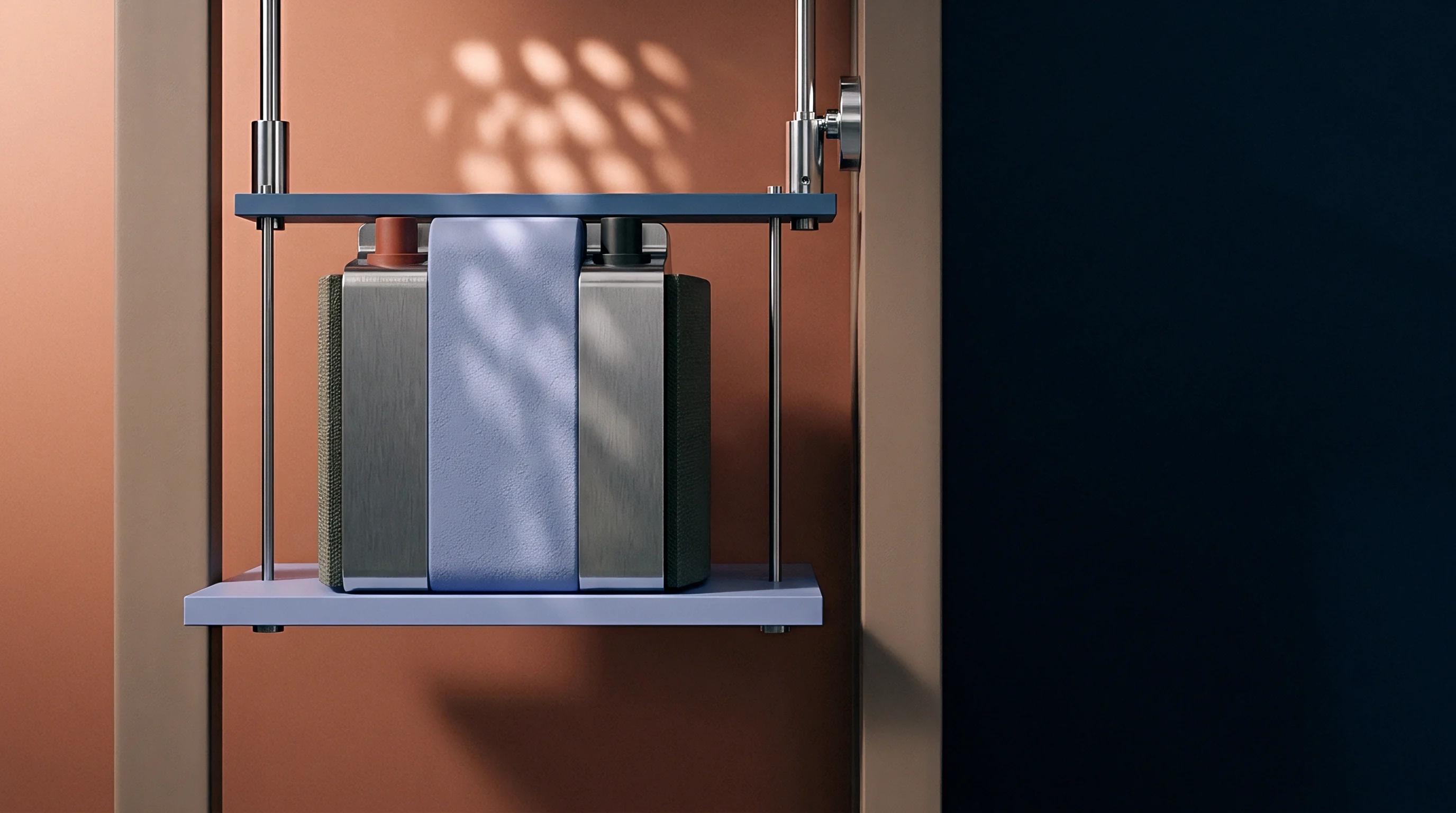
Rigid aluminum endplates clamped by high-tensile steel tie rods maintain the compressive load needed to keep solid cell layers in contact. During cycling, lithium intercalation into cathode hosts and neat lithium plating at the anode drive continuous macroscopic thickness changes. Pure lithium metal exhibits an unconstrained volume change of roughly 100 percent across plating and stripping, generating 5 to 15 percent linear stack expansion depending on anode thickness and design porosity.
If a pack incorporates an overly rigid compression frame, cell thermal expansion combined with phase-change swelling during charge can force internal stress beyond 15 megapascals, crushing porous ceramic separators, cracking brittle oxide pellets, or extruding metallic lithium past seal borders. Conversely, an overly compliant fixture ~ or spring washers that relax under load over time ~ lets stack pressure collapse during thermal contraction and discharge shrinkage, opening voids along the solid interface.
Mechanical Stack Pressure Maintenance
Achieving uniform face pressure across large-format solid-state pouches or prismatic cells is difficult in series production. Cumulative tolerances from pouch envelopes, dielectric aerogel pads, cold-plate fins, and endplate machining can swing local pressures by more than plus or minus 25 percent across the active electrode face. Thermal gradients compound the problem as differential expansion shifts the load between the steel chassis, aluminum heat sinks, and composite cell stacks.
Under sharp temperature spikes, sulfide electrolyte matrices yield at localized stress concentrations, permanently changing the interface topology. As the cell cools, this deformed electrolyte can no longer conform to the contracting lithium foil, leaving interfacial gaps that permanently increase constriction resistance. Several structural mechanisms undermine contact stability inside modules:
- Interfacial Creep Relaxation occurs where localized high-temperature spikes cause sulfide electrolyte particles to deform irreversibly under static mechanical load.
- Disc Spring Thermal Settling degrades active clamping force when Belleville spring packs experience thermal cycles beyond eighty degrees Celsius inside unvented enclosures.
- Anode Cavitation creates physical separation between the negative electrode collector foil and the solid separator during rapid low-temperature discharge sequences.
- Tie Rod Elongation produces permanent structural yield in module tie bars subjected to concurrent thermal expansion and maximum state-of-charge cell swelling.
Every mechanism listed above degrades the electrical and thermal contact conductance between the cell and its cooling interface. As contact resistance rises unevenly, the cell loses its ability to shed heat symmetrically, widening the thermal gap between parallel cells during subsequent operating pulses.
Constriction Resistance at Asperity Contacts
Neither ceramic separators nor metallic lithium foils are flat at the micron scale. True mechanical contact is restricted to microscopic asperities covering just 2 to 10 percent of geometric area under standard pack pressures. Electrical current and heat flux must bottle through these narrow junctions.
Constriction resistance scales inversely with this true contact area, governed by the ratio of applied compressive stress to the yield hardness of the softer material.
Because lithium softens rapidly as temperature climbs, asperities in a warm cell flatten more easily under constant clamping pressure. As true contact area grows, constriction resistance falls alongside charge-transfer resistance. In a colder companion cell, rigid lithium preserves high constriction resistance, accelerating the divergence in total branch impedance across the parallel group.
In module mechanical design, active spring compliance maintains interface contact much more reliably than rigid tie bolts.
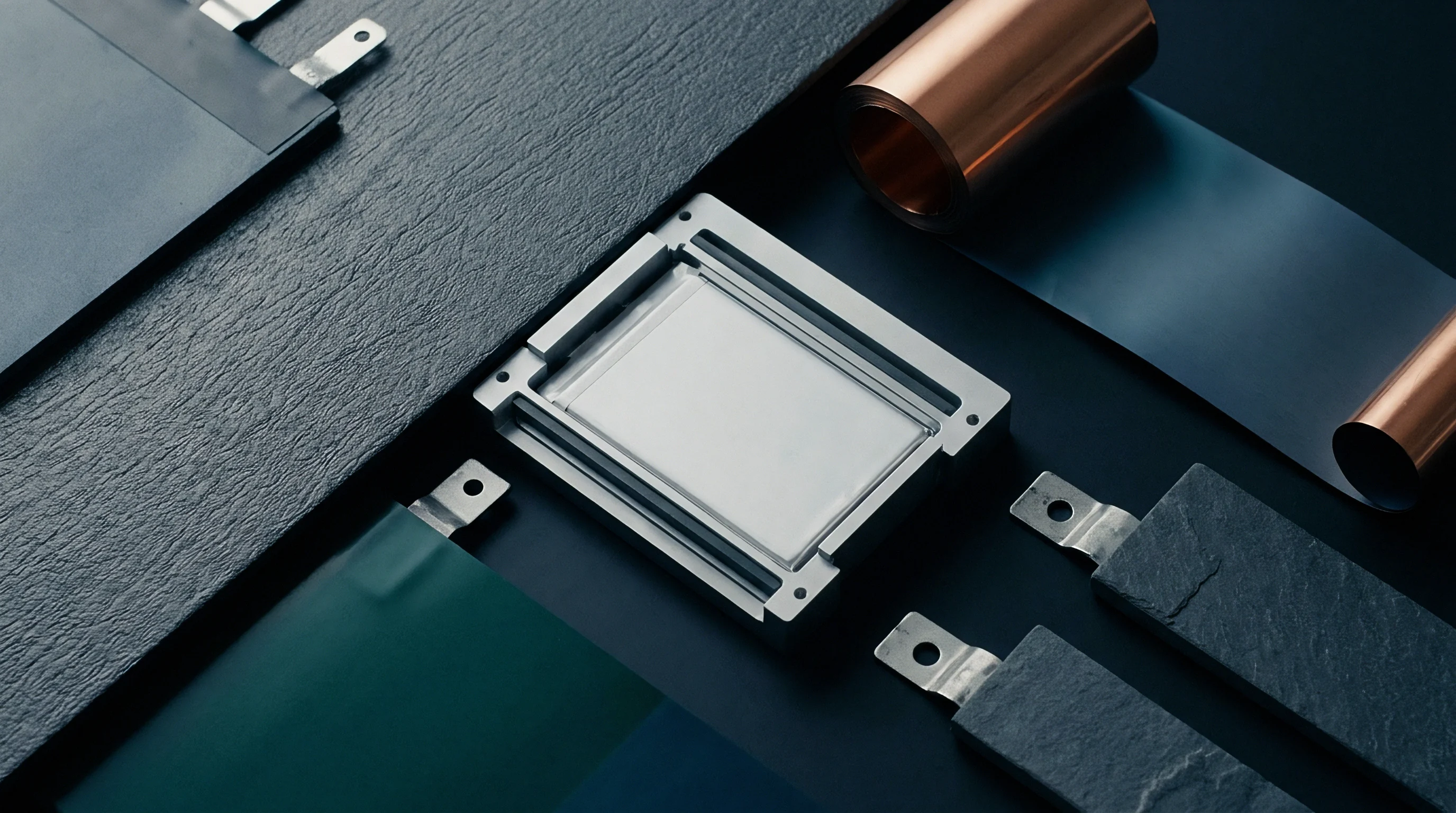
Branch
Current distribution across parallel cells tracks the path of lowest impedance across multiple frequency regimes. At sub-millisecond scales, parasitic inductance and busbar resistance govern current paths. Between ten milliseconds and ten seconds, interfacial charge-transfer resistance and double-layer capacitance dominate the circuit.
Beyond ten seconds, branch balance is dictated by solid-state diffusion, mass transport, and thermal time constants.
In a parallel group of four 50 ampere-hour solid-state cells on a shared busbar, even a two-degree thermal split between inner and outer cells during high-rate charging causes the warmer inner units to draw 35 percent of pack current, stranding colder outer cells at half their rated intake. The calculation below illustrates this divergence inside a 4P module operating across a representative thermal gradient.
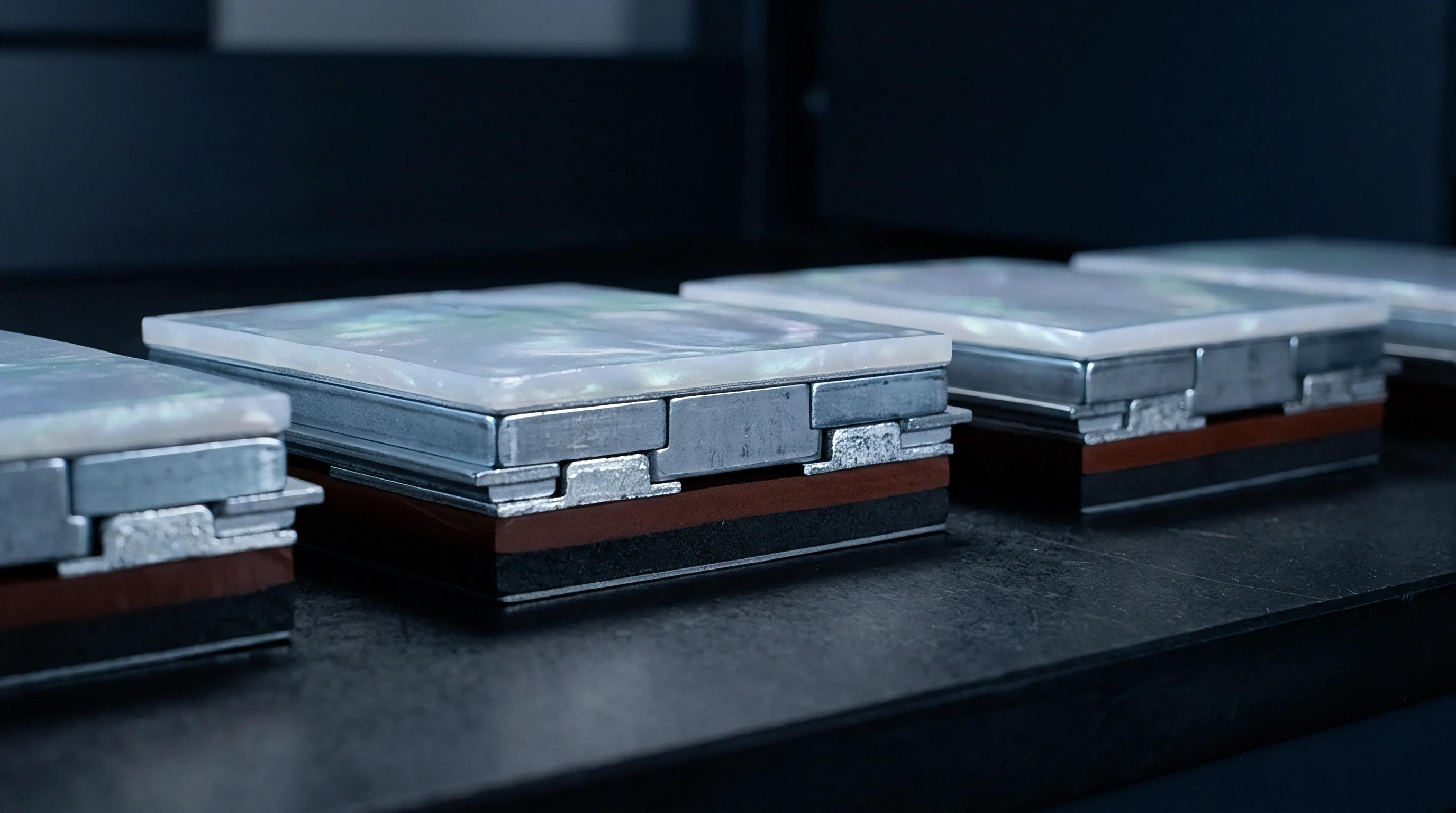
Which Thermal Threshold Triggers Irreversible Local Degradation?
Current imbalances become self-reinforcing once local Joule heating outpaces heat conduction through the cell face. The crossover arrives when the derivative of heat generation with respect to temperature exceeds conductance to the heat sink. At that threshold, the cell enters positive electro-thermal feedback: falling impedance draws higher current, generating more heat, which drops impedance further until the solid separator shorts or cracks under dendrite growth.
No single temperature delta threshold applies universally across all solid chemistries, since the trigger shifts with cell format, interfacial roughness, and separator thickness. For sulfide pouch cells operating above 1.5C, an inter-cell gradient of 4.5 degrees Celsius suffices to push localized current densities beyond the critical threshold of 2.0 milliamperes per square centimeter. Module cooling architectures must therefore restrict transient inter-cell gradients below 3.0 degrees Celsius across all certified drive cycles.
A four-cell parallel branch tolerates no more than a three-degree thermal gradient before current imbalance exceeds twenty percent under two-C continuous charging.
Consider a module where cell one sits directly above a 25 degrees Celsius coolant inlet while cell four rests on an uncooled edge at 35 degrees Celsius. Under a total charging current of 200 amperes ~ nominally 50 amperes per cell across the 4P group ~ cell branch values resolve as follows.
| Cell Position | Operating Temperature (C) | Interfacial ASR (ohm cm²) | Branch Impedance (mOhm) | Calculated Current (A) | Current Density (mA/cm²) |
|---|---|---|---|---|---|
| Cell 1 (Inlet) | 25.0 | 24.5 | 1.45 | 37.2 | 1.24 |
| Cell 2 (Mid-Cool) | 27.5 | 20.8 | 1.31 | 41.2 | 1.37 |
| Cell 3 (Mid-Warm) | 31.0 | 16.5 | 1.14 | 47.4 | 1.58 |
| Cell 4 (Stagnant) | 35.0 | 12.8 | 0.99 | 54.2 | 1.81 |
Cell four draws 54.2 amperes, running 27 percent above its nominal 50-ampere rating, while cell one drops to 37.2 amperes. This shift pushes cell four directly to its critical current density limit of 1.8 milliamperes per square centimeter. Resolving transient branch currents across parallel cells follows a standard calculation sequence:
- Establish the baseline open-circuit voltage and state-of-charge for each individual cell branch in the parallel set.
- Measure or compute the temperature of each cell node using thermal sensor telemetry or discretized finite-volume thermal mesh nodes.
- Update the temperature-dependent interfacial area-specific resistance and bulk electrolyte resistance via Arrhenius equations specific to the cell lot.
- Calculate the equivalent resistance of each branch, including cell terminals, busbar run lengths, and weld interface resistances.
- Solve the coupled nodal matrix using Kirchhoff current and voltage equations to determine instantaneous branch currents and local volumetric heat generation rates.

Dynamic Current Partitioning in Parallel Cells
Pulsed loads expose impedance variations that steady-state tests mask. During five to fifteen-second regenerative braking events, double-layer capacitance absorbs the initial voltage swing before the charge-transfer interface takes the bulk of the load. Because double-layer capacitance charges in milliseconds while the thermal time constant of a 50-ampere-hour cell runs between 80 and 200 seconds, electrical branches unbalance almost immediately, well before thermal sensors detect any surface shift.
When high-rate charging occurs across an uneven thermal field, cold cells fail to take their share, forcing warmer branches to absorb current spikes that degrade the lithium interface. A similar divergence occurs across parallel dies in silicon carbide power modules, where uneven thermal paths funnel current into the hottest die until bond wires shear from fatigue. In solid-state battery packs, the failure is localized separator penetration by lithium dendrites rather than an open circuit.
Whether battery management hardware can actively balance parallel branch currents through sub-milliohm trimming circuits remains an open question for automotive packs.
Chill
Thermal management in solid-state packs requires far tighter surface uniformity than liquid-electrolyte designs demand. Liquid cells rely on internal pore diffusion and mild convection to smooth out localized heating, but solid cells depend entirely on conduction through composite cathodes, dense separators, and current collector foils. Through-plane thermal conductivity in a stacked pouch cell rarely exceeds 1.2 watts per meter-kelvin, whereas in-plane conductivity along copper and aluminum foils reaches 25 to 35 watts per meter-kelvin.
Under continuous mechanical cycling, standard thermal interface pastes pump out from between pouch cells and cooling plates, leaving air pockets that cut local heat transfer coefficients by an order of magnitude. As thermal resistance degrades unevenly across the pack, edge-to-center temperature deltas grow and exacerbate current imbalances on parallel branches.
Transient Cold Plate Boundary Conditions
Cooling plates engineered for average heat rejection struggle with transient spikes. Single-pass serpentine channels create an unavoidable fluid temperature rise from inlet to outlet: in a 500-millimeter-long cold plate flowing 50-50 water-glycol at four liters per minute, the fluid warms by 4 to 6 degrees Celsius during a 3C fast charge. That rise maps directly onto the row of parallel cells seated along the flow path.
When clamping fixtures load cells against cold plates at five megapascals, the plates bow unless backed by rigid internal ribbing. Plate deflection creates uneven contact pressure across cell faces, widening variances in thermal contact resistance. Interface properties governing heat rejection into the plate are summarized below.
| Interface Boundary | Layer Thickness (mm) | Thermal Conductivity (W/m K) | Contact Conductance at 5 MPa (W/m² K) | Mechanical Compliance |
|---|---|---|---|---|
| Cell Face to Silicone Gap Pad | 0.50 ±0.05 | 3.0 | 1800 | Elastomeric Compression |
| Cell Face to Graphite Sheet | 0.15 ±0.02 | 12.0 (Through-plane) | 3200 | Low Plastic Deform |
| Direct Cell to Anodized Plate | Dry Contact | — | 650 | Rigid Metal Asperity |
| Structural Polyurethane Adhesive | 0.25 ±0.03 | 1.8 | 2400 | Cured Cross-Linked |
| Values reflect experimental guarded hot plate measurements per ASTM D5470 under five megapascals uniform mechanical stress. | ||||
Graphite sheets provide strong thermal conductance but lack dielectric strength and require tightly controlled surface flatness. Structural polyurethane adhesives prevent pump-out and bond cells mechanically, though they make pack disassembly and teardown inspections difficult. Assembling parallel modules without qualifying the long-term integrity of these interface materials risks thermal bottlenecks during high-rate charging.
Thermal Resistance Paths across Module Stacks
Double-sided cooling reduces through-plane temperature deltas across thick stacks, but it adds packaging volume, seal count, and plumbing complexity. Bottom-only plates save mass and simplify hose routing, but they leave steep vertical gradients between the base of the electrode stack and the top terminals. Tab cooling pulls heat directly from collectors where current concentration peaks, easing terminal hotspots, but the narrow foil cross-section cannot reject enough heat from the cell core.
When persistent thermal gradients create permanent hot spots in parallel groups, accelerated degradation forces the battery management system to de-rate module power well before cells reach their design cycle life. Omitting transient thermal models from module packaging work routinely leads to premature field retirement and unrecoverable warranty claims.

Recourse
Cell supply specifications frequently obscure interfacial impedance risks behind steady-state cycling claims. Cell manufacturers routinely qualify solid-state cells at 0.2C rates inside environmental chambers held at 45 degrees Celsius under laboratory hydraulic presses. Those gentle conditions depress interfacial charge-transfer resistance and mask the thermal gradients that develop in parallel packs under automotive duty.
Commercial contracts need to anchor cell sorting, grading, and warranty thresholds to transient operational metrics rather than bench data from isolated cells.
When parallel cells diverge under operating gradients, warranty investigations often stall over whether shorts originated from separator defects or uneven pack cooling. Unless the integrator proves that the cooling system kept inter-cell temperature deltas within contract limits, the cell vendor will dispute liability for capacity loss or internal shorting. Clear factory acceptance gates and operating boundary definitions protect the buyer against disputed field failures.
Factory Acceptance Gates for Matched Cell Groups
Receiving inspection for solid-state cells going into parallel strings demands impedance screening across multiple frequency bands. Standard 1-kilohertz alternating-current checks capture only bulk electronic and high-frequency ionic resistance, missing the low-frequency interfacial charge-transfer impedance where thermal sensitivity actually sits. Sorting protocols must pair high-frequency checks with multi-temperature impedance spectroscopy or high-rate pulsed direct-current characterization.
If baseline interfacial area-specific resistance across cells in a parallel lot varies by more than 8 percent at 25 degrees Celsius, normal operating gradients will drive branch current maldistribution past acceptable limits within fifty thermal cycles. Supply specifications must tie lot release to narrow variance bands for both room-temperature impedance and the temperature coefficient of resistance. Cells falling outside these limits cannot enter parallel assemblies without compromising pack reliability projections.
Incoming quality inspection standards must reject solid-state cell batches showing more than an eight percent coefficient of variation in interfacial charge-transfer resistance across five sample locations.
Contractual Allocation of Interface Fatigue Losses
Procurement contracts must draw a clear line between cell-level structural integrity and pack-level thermal-mechanical operating limits. The cell vendor warrants that the electrolyte interface will maintain mechanical cohesion and critical current density thresholds, provided clamping pressure stays inside a specified band and inter-cell temperature differences remain bounded. In turn, the pack builder warrants that cooling hardware will prevent transient temperature spreads from exceeding agreed limits under specified charge and discharge duty.
Section 8.4 of the module supply master agreement explicitly stipulates that warranty liability for internal short circuits reverts entirely to the cell manufacturer if the pack telemetry log confirms that inter-cell thermal gradients remained below 3.5 degrees Celsius and external clamping pressure remained between 4.0 and 6.0 megapascals throughout the operating life of the pack.