Thermal Strain Mitigation in Copper Alloy Tool Inserts
Mitigating thermal strain in copper tool inserts demands floating slip pockets and spring preloads that absorb expansion while preserving interfacial contact.
Expansion
Melt enters at 285 degrees Celsius, placing injection molding cycles for cylindrical cell carriers and thin-wall module partitions under severe thermal demands during high-volume battery pack manufacturing. Polymer melts such as 30 percent glass-filled polybutylene terephthalate or flame-retardant polycarbonate hit cavities at temperatures between 260 and 300 degrees Celsius, while the mold base steel runs at 40 to 60 degrees Celsius to freeze structural details quickly. Conventional core pins machined from AISI P20 or AISI H13 pull heat slowly because of their low bulk thermal conductivity of 24 to 32 W/(m·K).
To shorten cycles, tool designers swap in high-conductivity copper alloys, driving dwell times down from 45 seconds to below 22 seconds across 21700 and 46800 cell matrices. That productivity gain, however, triggers an immediate mechanical conflict driven by divergent coefficients of thermal expansion.
Over standard operating spans, AISI H13 tool steel shows a linear thermal expansion coefficient between 10.8 and 11.9 × 10⁻⁶ / K, whereas tooling copper alloys like C17200 beryllium copper and C18000 copper-nickel-silicon-chromium expand at 16.5 to 17.5 × 10⁻⁶ / K. When molten polymer contacts the cavity face, the copper insert surface spikes to 220 degrees Celsius while chilled water lines keep the surrounding steel block cold, opening an expansion differential greater than 5.5 × 10⁻⁶ / K across every cycle. Left unconstrained, a 200-millimeter copper insert would expand 0.176 millimeters along its primary axis across a 160-degree temperature rise.
A temperature delta of one hundred degrees Celsius produces eighty microns of unrestrained lateral growth across a two-hundred-millimeter copper insert.
Thermomechanical Mismatch in Battery Tooling
Tight thermal cadences govern cylindrical cell carrier tooling, where pocket consistency dictates automated pack assembly yields. A core shift of just 0.04 millimeters causes cells to bind in pick-and-place grippers, tearing shrink-wrap insulation and shutting down the pack line. Furthermore, module integrity depends on 0.8-millimeter plastic separator ribs between neighboring cells to halt thermal runaway propagation.
The inserts forming these delicate ribs absorb sharp thermal shocks on every shot: heat dumps into the copper core pin, driving rapid volumetric swelling while the colder P20 steel plate around it resists any displacement.
Immense contact pressures develop at the boundary. Beryllium copper has an elastic modulus of 131 GPa at room temperature, softening slightly toward 200 degrees Celsius, whereas the tool steel around it sits at 205 GPa. Locking that copper insert into a zero-clearance pocket creates severe triaxial compressive stress.
Under plane strain conditions, constraining a 160-degree Celsius temperature differential induces compressive thermal stresses beyond 380 MPa in the copper core. That level exceeds the proportional elastic limit of lower-strength copper grades, kicking off cyclic plastic deformation.

Mechanical Stress under Cavity Constraint
Securing copper cores with rigid socket-head cap screws invites trouble as thermal growth generates heavy compressive reactions. Plastic upsetting occurs right during dwell: the insert expands against rigid cavity walls and yields at peak mold face temperatures. Once the part solidifies and the cooling circuit draws heat out, the insert contracts back toward ambient temperature.
Because it suffered plastic strain at peak heat, it returns to a smaller volume than it started with, leaving micro-gaps between the insert body and the steel cavity pocket.
The resulting air gap acts as an insulator, since air displays a static thermal conductivity of only about 0.026 W/(m·K). An interface separation of just 15 microns cuts thermal conductance by more than eighty percent relative to a solid metal-to-metal contact interface held at 20 MPa contact pressure. Deprived of its primary heat path into the chilled mold base, the insert overheats and cycle times drift upward.
Technicians begin seeing hot spots on the core pins, leading to sink marks, sluggish ejection, and warped cell retention pockets.
| Material Grade | Thermal Conductivity (W/m·K) | CTE (10⁻⁶/K) | Yield Strength (MPa) | Elastic Modulus (GPa) | Hardness (HRC / HRB) |
|---|---|---|---|---|---|
| AISI H13 Tool Steel | 28.6 | 11.5 | 1380 | 198 | 48 HRC |
| AISI P20 Steel | 31.2 | 12.1 | 860 | 202 | 32 HRC |
| C17200 Beryllium Copper (TH04) | 115.0 | 17.0 | 980 | 128 | 40 HRC |
| C18000 CuNiSiCr (TF00) | 215.0 | 16.8 | 620 | 135 | 94 HRB |
| C18200 CuCr (TH04) | 320.0 | 17.4 | 360 | 120 | 78 HRB |
Without thermal strain relief, the assembly deforms the steel pocket permanently, creating flashed cell carrier ribs that pinch cell sleeves and cause electrical isolation faults on automated module assembly lines.
Alloy
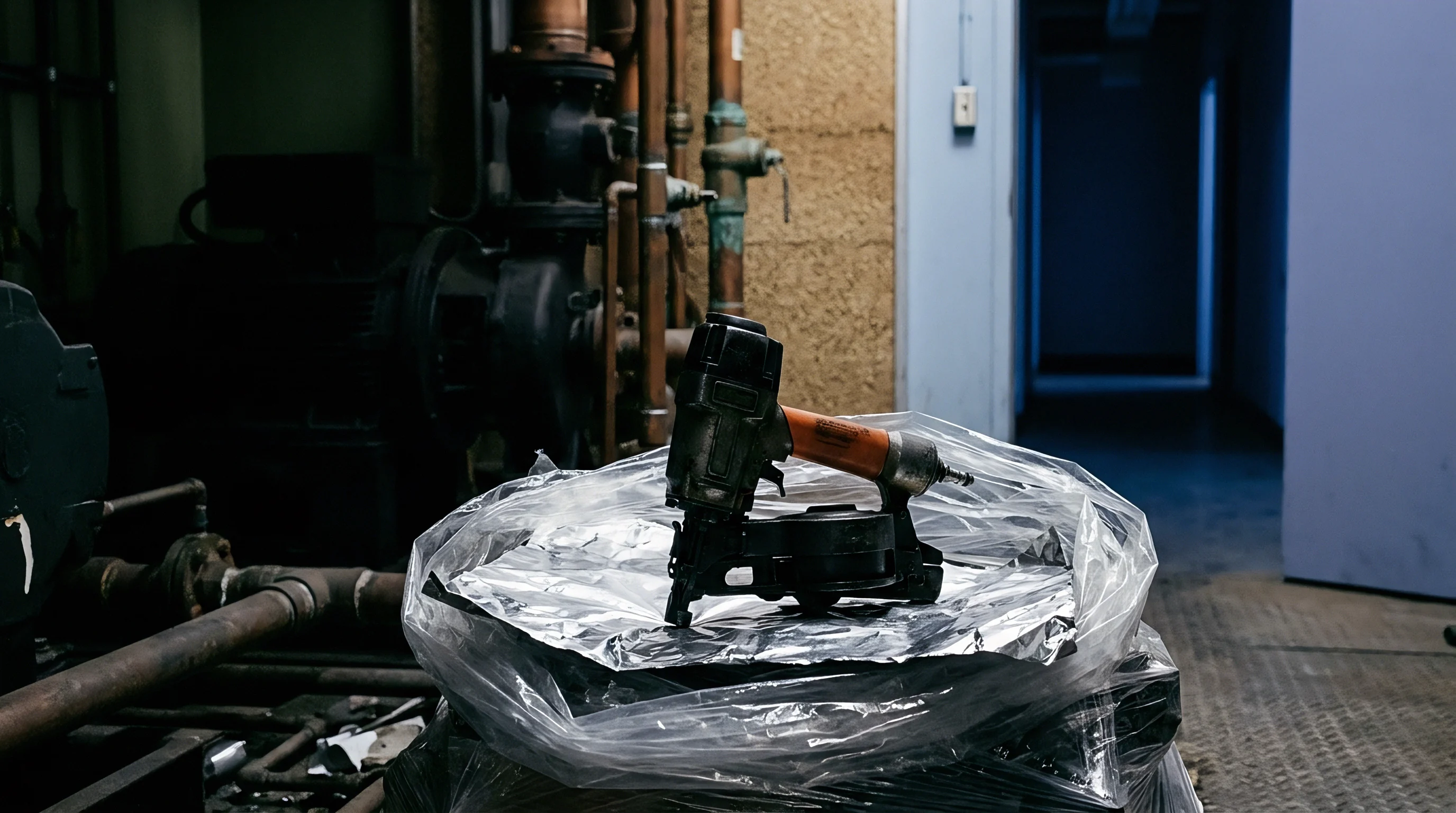
Specifying alloys for high-takt battery carrier tooling forces a balance between heat dissipation and yield resistance. C17200 contains roughly 1.8 to 2.0 percent beryllium with trace cobalt and nickel. Solution heat treatment and precipitation aging to the TH04 temper boost yield strength past 960 MPa and hardness to 38 to 42 HRC, which provides enough structural stiffness to resist plastic upsetting against steel cavity walls.
Its bulk thermal conductivity runs between 105 and 130 W/(m·K) ~ roughly four times that of H13 tool steel, though only half the rating of softer copper grades.
Yield strength falls off once temperatures push past 200 degrees Celsius. C18000 offers a different metallurgical profile by combining copper with nickel, silicon, and chromium. Precipitation aging produces fine nickel silicide intermetallics that strengthen the matrix without clogging electron conduction paths.
This delivers a thermal conductivity of 200 to 230 W/(m·K) alongside a yield strength of 550 to 650 MPa. In core pins where operating gradients stay under 120 degrees Celsius, C18000 pulls heat fast enough to trim cycle times by an extra twelve percent compared to beryllium copper. Under rigid pocket confinement at higher heats, however, it undergoes micro-yielding and requires deliberate expansion clearances to avoid permanent dimensional shortening.
Conductivity against Yield Stress Tradeoffs
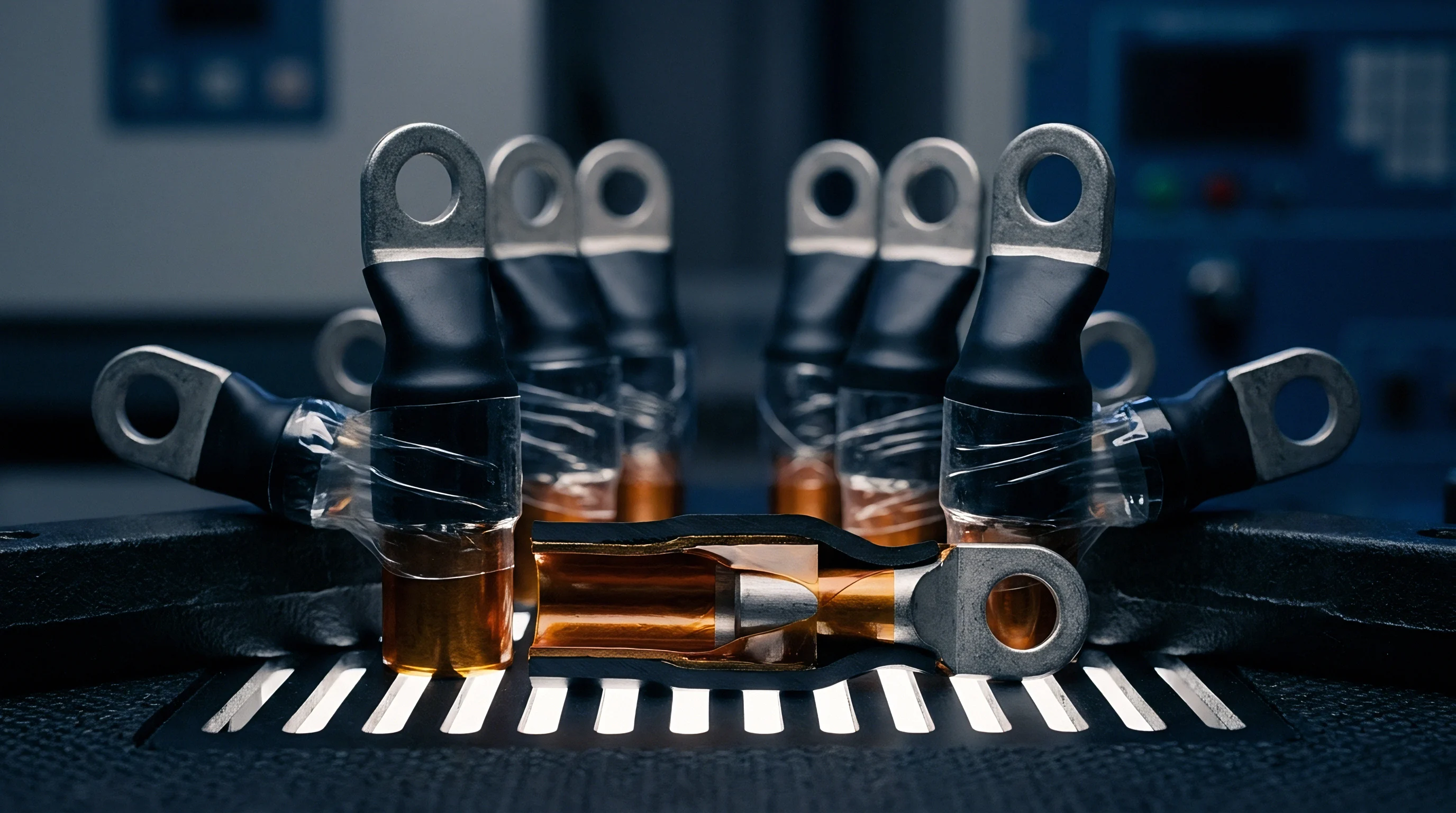
Balancing rapid thermal conduction against mechanical endurance remains tricky with alloys like C18200 copper-chromium, which reaches thermal conductivities near 320 W/(m·K) ~ about eighty percent of pure copper performance. While chromium precipitates keep the matrix stable up to 400 degrees Celsius, yield strength tops out between 340 and 420 MPa. Under cavity packing pressures and thermal expansion, rigid pockets will permanently crush C18200 inserts.
Tool designers therefore relegate C18200 to deep internal sub-inserts well away from parting lines and shut-off faces.
Where components must slide under high compressive loads, aluminum bronzes provide a practical alternative for wear surfaces. Compositions like CuAl10Fe5Ni5 reach yield strengths above 680 MPa and resist galling against P20 steel pockets. Their thermal conductivity drops to 45 to 60 W/(m·K), ruling them out as primary chill inserts, but they work effectively as intermediate guide shoes or floating wear sleeves that allow high-conductivity copper cores to expand axially without seizing against raw steel pocket walls.
European battery pack programs reject tooling containing toxic additives to avoid hazardous waste classifications under regional occupational health directives.
Environmental Regulations Governing Beryllium Machining
Dry grinding and electrical discharge machining of beryllium copper face tight workplace restrictions. Machining and high-speed milling release respirable particles capable of causing chronic beryllium disease, leading regulators to mandate eight-hour exposure limits below 0.2 micrograms per cubic meter of air. Shops working with C17200 must install dedicated downdraft hoods, isolate wet-grinding cells, and maintain scrap chain-of-custody tracking.
These safety controls add ten to fifteen percent to the landed cost of finished beryllium copper mold cores.
These hazards lead many automotive battery programs to prohibit beryllium outright in tooling contracts. Material bans written into requests for quotation push mold makers toward C18000 CuNiSiCr or high-purity copper-chromium-zirconium alloys, altering the mechanical design envelope. Without the 1000 MPa yield strength of C17200 to withstand tight interference fits, tool engineers must incorporate active thermal strain relief into the pocket design so lower-yield copper alloys do not buckle under cyclic compressive loads.
Thermal strain damage appears across distinct physical interfaces inside battery enclosure tooling:
- Parting line crushing occurs when axial thermal expansion forces the copper core pin beyond the steel cavity split line, coining the opposing mold face and producing plastic flash across cell nest openings.
- Interfacial air decoupling develops when cyclic plastic upsetting causes the cooled insert to shrink away from the steel pocket, dropping localized heat dissipation efficiency by more than seventy-five percent.
- Fretting oxidation wear generates black copper oxide debris along sliding pocket fits, accelerating clearance degradation and introducing metal contamination into the injection mold cavity.
- Cooling channel cavitation forms where cyclic mechanical deflection flexes thin copper walls surrounding internal water baffles, eroding metal and causing internal coolant leaks into the plastic part.
Standard copper core pins can seat firmly once injection temperatures stabilize, but treating initial fit clearances as immaterial consistently degrades part concentricity.

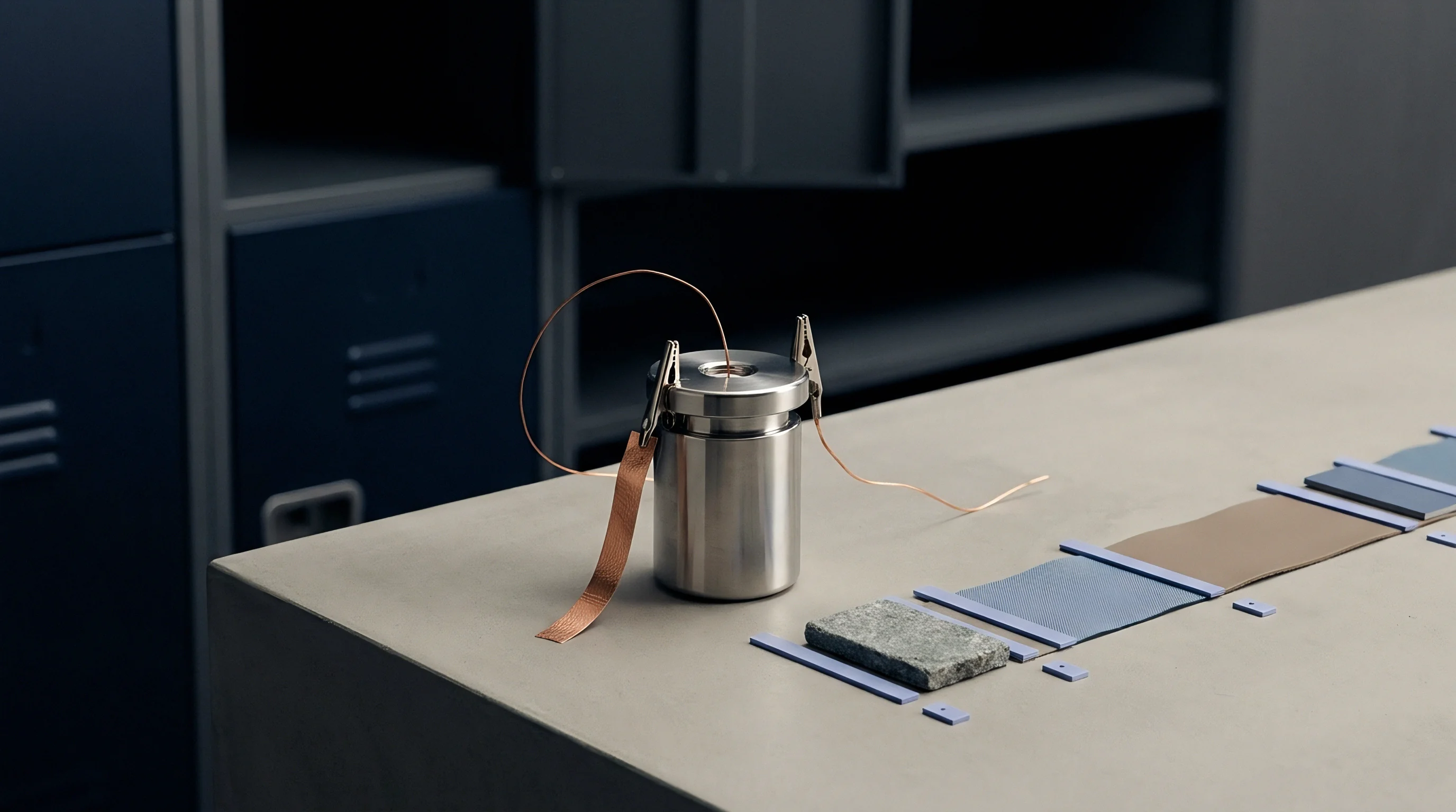
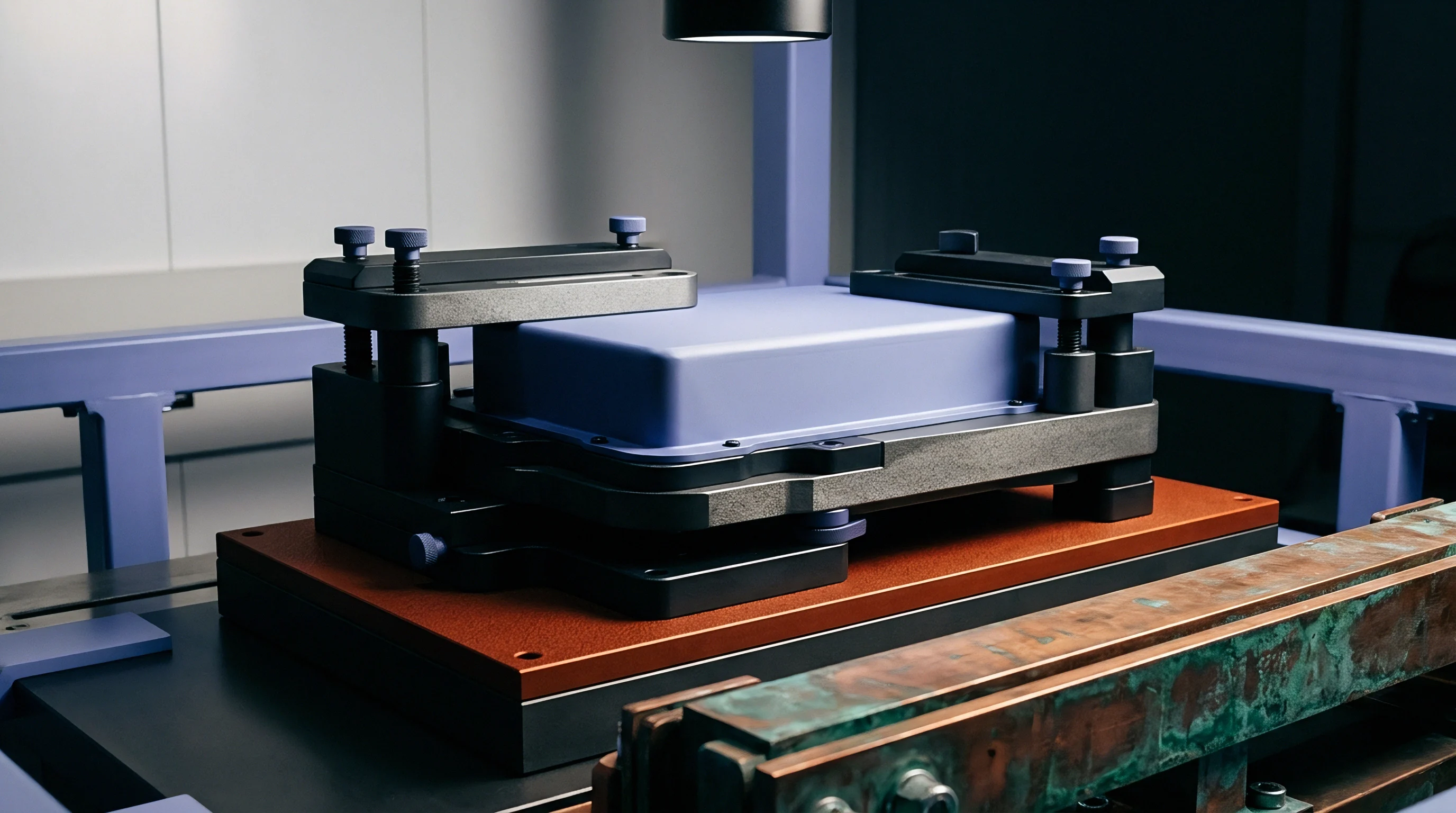
Preventing thermal strain damage in copper tool inserts requires moving away from traditional line-to-line or light press fits. An insert machined line-to-line at 20 degrees Celsius expands aggressively against cavity walls once the tool reaches an operating equilibrium of 80 to 140 degrees Celsius. Instead of locking the insert down, designers use floating pocket geometries.
Grinding deliberate lateral clearance into the P20 or H13 receiver pocket lets the copper breathe radially while anchoring it along an isolated reference datum.
If an open clearance gap fills with air, interfacial heat conduction plunges from 8,000 W/(m²·K) under intimate metal contact down to 400 W/(m²·K) ~ a drop of roughly ninety percent. Maintaining thermal coupling without mechanical seizure requires compliant conductive media, such as high-conductivity metallic interface foils or graphite transfer compounds. Flexible silver-coated copper shims accommodate twenty to thirty microns of cyclic breathing while routing heat into the cooled mold base.
Thermal contact resistance across dry tooling interfaces drops as mechanical clamping pressure increases.
Tolerancing Strategies for Differential Expansion Fits
Sliding engagement is typically established with precision-ground stepped diameters. At the cooler base, a locating register held to plus 0.005 to plus 0.010 millimeters mates into a ground bore in the steel mold plate. Along the working body and tip, where temperature swings exceed 180 degrees Celsius, the insert is machined undersize.
This diametral gap follows an expansion budget of 0.0012 millimeters per millimeter of insert diameter for every 100 degrees Celsius of projected temperature differential between the copper and the steel.
Rigid bolting virtually guarantees mechanical failure during axial thermal expansion. Replacing solid cap screws with disc spring stacks inside counterbored retention pockets accommodates length growth under load. Belleville washers stacked in parallel-series sets exert a steady 15 to 25 kN seating force against the insert shoulder throughout the molding cycle.
When the copper core extends axially on injection, the spring stack deflects, taking up 0.08 to 0.15 millimeters of movement without overstressing the retaining screw.
Will Floating Fits Eliminate Galling Seizure?
Unconstrained expansion prevents gross distortion, but sliding contact between dissimilar metals introduces adhesive galling risks under repeated thermal cycling. Copper exhibits high friction when rubbed directly against unhardened or raw tool steel under pressure. To keep components sliding cleanly across five hundred thousand cycles, surfaces receive physical vapor deposition coatings.
A 3-micron deposit of chromium nitride or diamond-like carbon on the steel pocket walls drops the friction coefficient below 0.15, letting the copper expand without micro-welding or metal transfer.
Centerline positioning across multi-cavity cell carrier inserts cannot rely on perimeter walls once radial clearance gaps are cut. Designers use cross-keys or slotted dowels instead. A precision center dowel fixes the neutral thermal axis, while secondary pins slide inside radial slots oriented along the lines of expansion.
As temperatures climb, the copper insert expands outward along the guide slots without shifting off center, maintaining true position tolerances on cell carrier nest centers within 0.015 millimeters over extended runs.
Machining and installing thermal strain mitigating inserts follows a rigorous mechanical sequence:
- Bore the P20 receiver pocket to the finish dimension with a surface roughness of Ra 0.4 microns.
- Machine the copper alloy insert with lateral expansion allowances calculated from the maximum operating thermal delta.
- Install guide pins with elongated slot bushings along the primary expansion axis to maintain centerline location.
- Preload the base retaining screws through calibrated disc spring stacks to allow axial breathing without tool bind.
Interfacial Conductance and Surface Contact Pressures
Microscopic surface asperities govern actual heat transfer across the steel-copper interface. Solid contact occurs only at these peaks, covering less than five percent of the nominal footprint under standard assembly torque. Increasing spring preload crushes these peaks elastically and plastically, broadening the true contact area and improving interfacial thermal conductance.
Operating data indicates that maintaining contact pressure above 18 MPa stabilizes heat flow through the mechanical seam without triggering adhesive wear.
With interface conductance through floating gaps trailing bulk metal rates, advanced tooling routes cooling water at 4 bar directly through the copper insert, bypassing the mechanical joint entirely. Water channels drilled into C18000 cores must leave at least 4.0 millimeters of ligament thickness to the molding surface to avoid fatigue cracking from thermal and hydraulic cycling. Bridging coolant across the moving insert boundary calls for dynamic elastomer seals engineered to handle continuous breathing.
Inserts guided by center keys expand outward symmetrically without binding against pocket walls.

Fatigue
Automated carrier tooling running three shifts logs over one million thermal cycles every year. Each shot hits the copper face with a rapid thermal shock, followed immediately by pack pressure and chilled-water extraction. The resulting temperature swings generate cyclic plastic strain.
Under these low-cycle fatigue conditions, insert life tracks the total plastic strain range per shot in accordance with the Coffin-Manson relationship.
Trapping a copper insert rigidly inside a steel cavity can push the cyclic plastic strain range above 0.2 percent. Under that degree of cyclic work, even unnotched C18000 components develop grain-boundary fatigue cracks in fewer than eighty thousand shots, starting at cooling channel corners and sharp external radii. Once cracks breach the water jacket or cause the core to fracture during mold opening, the entire pack line halts.
Relieving the constraint with spring-loaded floating mounts drops the plastic strain range below 0.02 percent, extending crack-free service life past six hundred thousand shots.
Copper cores with sharp internal cooling corners develop surface microcracks long before unnotched components show plastic yield.
Where Do Thermal Gradients Trigger Crack Initiation?
Finite element calculations highlight intense strain concentrations at drilled coolant intersections. Between a 240-degree Celsius molding face and a 45-degree Celsius water passage just five millimeters away, the gradient nears 40 degrees Celsius per millimeter. The resulting differential thermal expansion inside the copper insert induces high shear stresses at the root of drilled water baffles, where helical tool marks left by gun drills act as microscopic stress risers that accelerate crack growth.
To keep tooling life from falling short of projections, toolmakers radius cross-hole intersections and polish internal passages. Methods like electrochemical deburring and abrasive flow machining smooth internal lines from Ra 3.2 microns down to Ra 0.4 microns, wiping out microscopic grooves that seed cracks. Pairing this finish with a minimum five-millimeter corner radius on all external pocket steps distributes thermal strain across the bulk alloy rather than concentrating deformation at structural notches.
Conformal Cooling Geometries and Elastomer Sealing
Building cooling channels directly inside the copper body removes reliance on heat transfer across steel cavity walls. Direct metal laser sintering makes it possible to print copper-chromium-zirconium inserts with complex conformal channels that hug the thin ribs of each cell nest. Holding an unbroken 3.0-millimeter distance from the molding surface around the full circumference of each 21700 pocket clears out hot spots, pulling peak temperatures from 240 degrees Celsius down to 140 degrees Celsius.
That lower peak temperature cuts overall thermal expansion displacement by over forty percent.
Dynamic coolant seals represent a persistent failure point in floating insert assemblies. Chilled water must cross from the stationary mold plate into the moving copper core without leaking into the molding cavity. Standard static O-rings shred quickly when subjected to 0.08 millimeters of axial insert breathing on every cycle, wearing out from scrubbing and extrusion against the elastomer.
Addressing this requires dual sealing systems featuring fluorocarbon (FKM) or perfluoroelastomer (FFKM) O-rings backed by virgin PTFE anti-extrusion rings housed in precision-machined stepped glands.
| Constraint Architecture | Insert Material | Strain Range per Shot (%) | Cycles to Crack Initiation | Primary Failure Location |
|---|---|---|---|---|
| Rigid Interference Pocket | C17200 (TH04) | 0.14 | 145,000 | Pocket split-line radius |
| Rigid Interference Pocket | C18000 (TF00) | 0.22 | 72,000 | Core pin shut-off face |
| Slotted Floating Fit | C18000 (TF00) | 0.04 | 480,000 | Coolant channel baffle root |
| Spring Preloaded Floating Fit | C18000 (TF00) | 0.02 | 750,000 | Internal cross-hole junction |
| Conformal Additive Floating Fit | CuCr1Zr | 0.015 | 920,000 | Secondary support shoulder |
| Endurance limits determined under simulated injection cycle conditions using 30% glass-filled PBT at 280 °C melt temperature and 50 °C chilled water delivery at 4.2 bar fluid pressure. | ||||
Maintaining tooling reliability over extended battery vehicle programs requires tracking physical fatigue indicators:
- Strain range verification utilizes transient thermal finite element models validated by embedded thermocouple data to ensure localized plastic strain stays below critical thresholds.
- Coolant flow monitoring continuously measures pressure drops across individual copper core circuits to detect internal scale buildup or early baffle deflection.
- Surface dye penetrant inspection screens tool shut-offs and pocket corners during scheduled maintenance intervals to intercept microcracks before catastrophic core breakage occurs.
It remains an open question whether additive manufacturing with functionally graded copper-to-steel powder transitions can eventually eliminate the mechanical interface altogether without generating brittle intermetallic zones under thermal cycling.
Ledger
Adding high-conductivity copper inserts to battery pack module tooling alters both upfront capital expenditure and ongoing operating costs. A multi-cavity injection mold producing 21700 cell carriers costs between 280,000 and 450,000 dollars, with precision-machined C18000 or C17200 inserts adding another 45,000 to 75,000 dollars in non-recurring engineering and machining. The investment earns its financial return by shaving cycle times from 38 seconds down to 21 seconds.
Across a production run of five hundred thousand battery packs, that difference saves hundreds of machine hours on 650-tonne injection molding presses, lowering part conversion costs.
That economic justification breaks down when thermal strain mechanics are ignored. When rigid mounting causes low-cycle fatigue failures at eighty thousand shots, contract molders face unplanned downtime, emergency tool extraction, and replacement insert fabrication costs of 8,000 dollars per incident. Tooling contracts must clearly define who pays for premature insert failure.
Unless the buyer establishes explicit thermomechanical design guidelines in the original tooling specification, tool builders routinely classify copper inserts as consumable wear items and cap warranty obligations at one hundred thousand cycles.
Tooling Contracts and Replacement Allocations
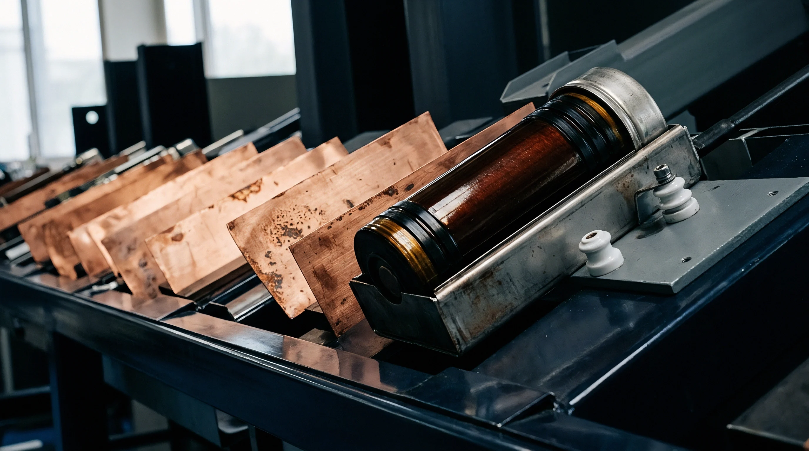
Contracts for high-volume cell carrier injection tooling normally establish spare part banks within capital purchase orders. A robust sourcing agreement mandates that the mold maker deliver the production tool alongside three complete sets of pre-fitted, serialized copper replacement inserts. These spare sets must undergo first-article dimensional verification at the tool shop using identical coordinate measuring machine routines.
Having qualified replacement inserts on the plant floor reduces downtime from six weeks of emergency manufacturing down to a single twelve-hour maintenance shift.
Tooling deposits can cover five spare sets while sourcing managers tie milestone payments to long-term endurance benchmarks. Final payment retention, typically ten to fifteen percent of total mold cost, should remain unreleased until the tool completes a continuous fifty-thousand-shot qualification run without insert binding, galling, or dimensional drift outside process capability limits. Contract language must specify that dimensional failure of plastic cell pockets caused by insert deformation constitutes a defect in tool construction rather than normal process wear.
A warranty seam opens when a toolmaker certifies cavity dimensions at room temperature while part rejection occurs under full thermal equilibrium.
Process Capability and Dimensional Acceptance Benchmarks
Quality teams track pocket dimensions through statistical measurement programs across pilot runs. In cylindrical cell modules, the critical dimension is pocket inner diameter and cylindrical runout, typically held to 21.40 plus or minus 0.04 millimeters. When copper core pins deform under cyclic thermal stress, the process capability index drops sharply.
Automotive battery quality plans require a CPK greater than or equal to 1.67 on all cell retention geometries; tool wear or insert displacement that drives CPK below 1.33 halts cell module assembly lines automatically.
To limit financial exposure, mold builders demand strict water filtration and maintenance protocols. Hard water scale deposits as thin as 50 microns inside copper cooling passages increase thermal resistance by thirty percent, driving up insert operating temperatures and accelerating thermal fatigue. Tool maintenance agreements mandate closed-loop demineralized water circuits with continuous flow monitoring.
If the molding facility operates unconditioned cooling water, the tooling supplier rejects warranty claims associated with thermal cracking or insert distortion.
Inserting an explicit tool maintenance clause tied to injection shot counters shifts the financial burden of insert replacement from the pack buyer to the injection molder once production exceeds three hundred thousand cycles.