Transverse Impact Anisotropy and Fatigue Limits in High Alloy Consolidated Steels
Transverse impact anisotropy drops high-alloy consolidated steel toughness up to 66 percent, requiring directional stress alignment to prevent fatigue failure.


Shell
Structural enclosures in high-density pack architectures rely on consolidated high-alloy steels to handle side-pole impacts, battery intrusion events, and continuous road shock. Processing routes like powder metallurgical consolidation, hot isostatic pressing, and secondary hot rolling bring ultra-high-strength iron-nickel-cobalt-molybdenum alloys to full theoretical density. Even so, the interaction of grain flow vectors, prior particle boundaries, and deformation axes leaves the preform strongly anisotropic.
When dynamic impact strikes perpendicular to the primary consolidation axis, absorbed fracture energy drops to a fraction of its longitudinal value.
Accounting for this directional bias is central to pack crash design. Standard UN 38.3 lateral impact trials and ISO 6469-3 side-crash stress fields subject member walls to multiaxial tension and shear. A casing wall machined from hot-rolled consolidated plate can show yield strength above 1800 MPa along the rolling axis.
Yet under transverse shear from a 100 kN crash load, micro-void coalescence starts along flattened prior particle boundaries at stress levels 35 percent below predicted longitudinal yield. Sizing prismatic casings or side-impact beams around longitudinal tensile test coupons risks catastrophic wall rupture during crash qualification.
Mill datasheets for powder-consolidated metals report mechanical properties taken almost entirely from longitudinal test bars aligned with the extrusion or rolling axis. That convention obscures the sharp drop in transverse elongation and dynamic impact resistance. Under abrupt lateral loads, the resulting transverse strain field quickly localizes deformation into narrow bands of segregated carbide clusters and flattened grain boundaries, promoting adiabatic shear bands and rapid wall penetration.
| Consolidation Route | Alloy Grade Family | Test Orientation | Yield Strength (MPa) | Charpy V-Notch (J) | Transverse Ratio (%) |
|---|---|---|---|---|---|
| Hot Isostatic Pressing | Fe-18Ni-9Co-5Mo (Maraging 300) | Longitudinal (L) | 2050 ± 25 | 24 ± 2 | 100 |
| Hot Isostatic Pressing | Fe-18Ni-9Co-5Mo (Maraging 300) | Transverse (T) | 1980 ± 30 | 14 ± 1.5 | 58.3 |
| Hot Isostatic Pressing | Fe-18Ni-9Co-5Mo (Maraging 300) | Short-Transverse (ST) | 1910 ± 35 | 8 ± 1.0 | 33.3 |
| Vacuum Powder Extrusion | Fe-3Cr-11Ni-1.2Mo (AerMet 100) | Longitudinal (L) | 1720 ± 20 | 42 ± 3 | 100 |
| Vacuum Powder Extrusion | Fe-3Cr-11Ni-1.2Mo (AerMet 100) | Transverse (T) | 1680 ± 25 | 26 ± 2 | 61.9 |
| Vacuum Powder Extrusion | Fe-3Cr-11Ni-1.2Mo (AerMet 100) | Short-Transverse (ST) | 1610 ± 30 | 15 ± 1.5 | 35.7 |
| Consolidated Powder Rolling | Fe-5Cr-1.3Mo-0.4V (PM H13) | Longitudinal (L) | 1650 ± 30 | 18 ± 1.5 | 100 |
| Consolidated Powder Rolling | Fe-5Cr-1.3Mo-0.4V (PM H13) | Transverse (T) | 1590 ± 35 | 9 ± 1.0 | 50.0 |
| Consolidated Powder Rolling | Fe-5Cr-1.3Mo-0.4V (PM H13) | Short-Transverse (ST) | 1520 ± 40 | 5 ± 0.8 | 27.8 |
Grain alignment governs energy absorption under high-rate deformation.
Integrating consolidated steel preforms into module frames means aligning principal impact vectors with the material’s consolidation flow lines. Profile-extruded side rails carry favorable grain alignment along their primary axis, but mounting flanges, machined pockets, and corner bend radii divert local stress fields away from it. A side impact then subjects outer flange corners to short-transverse tension ~ precisely where fracture toughness is lowest.
Structural failures in crash testing rarely stem from insufficient material section, tracing instead to localized transverse cleavage at these geometric transitions.
Consolidated high-alloy pack enclosure beams subjected to transverse shock vectors matching UN 38.3 rail impact conditions demonstrate this directional vulnerability directly. Beams machined parallel to the extrusion axis maintain structural integrity without cracking under a 50 g deceleration impulse. Conversely, beams machined with their primary load axis rotated ninety degrees to the extrusion direction exhibit through-wall cracking at 31 g deceleration.
The fracture surfaces display classical intergranular decohesion along original powder particle boundaries, showing that transverse impact performance depends on consolidation boundary integrity rather than bulk alloy chemistry.
What specific hot-isostatic densification schedules and thermo-mechanical reduction ratios successfully eliminate short-transverse impact embrittlement without degrading nominal yield strength?


Texture
Microstructural directionality dictates dynamic fracture behavior in consolidated alloys.
Powder metallurgical consolidation begins with atomization, freezing molten alloy streams into spherical droplets. During rapid solidification, elements like molybdenum, vanadium, and chromium segregate at dendrite boundaries. Hot isostatic pressing consolidates the powder under high temperature and pressure, but residual oxide films and titanium carbide networks often survive along prior particle boundaries.
Subsequent hot forging or rolling flattens these spherical interfaces into planar networks parallel to the working direction.
Carbide stringers provide ready paths for rapid crack initiation.
Under transverse loading, these elongated planar networks align directly with planes of maximum resolved shear stress. Tensile loads applied perpendicular to the rolling direction open micro-cracks along stringer interfaces with little plastic deformation. While longitudinal loading forces cracks to cut through matrix grains and absorb substantial energy, transverse stresses allow cracks to follow pre-existing microstructural interfaces, bypassing the energy-absorbing matrix volume almost entirely.
Transverse shear bands propagate along carbide stringers long before longitudinal yield strength is reached under shock loading.
Heat treatment can alter carbide morphology, but it cannot undo the grain flow texture created during consolidation rolling. Vacuum austenitizing followed by high-pressure gas quenching transforms the matrix to fine martensite, while secondary hardening tempers precipitate sub-micron vanadium and molybdenum carbides to push matrix yield strength beyond 1900 MPa. This high matrix strength concentrates stress at undissolved primary inclusion stringers, and the higher matrix hardness directly lowers transverse impact toughness ~ exacerbating mechanical anisotropy across the finished enclosure part.
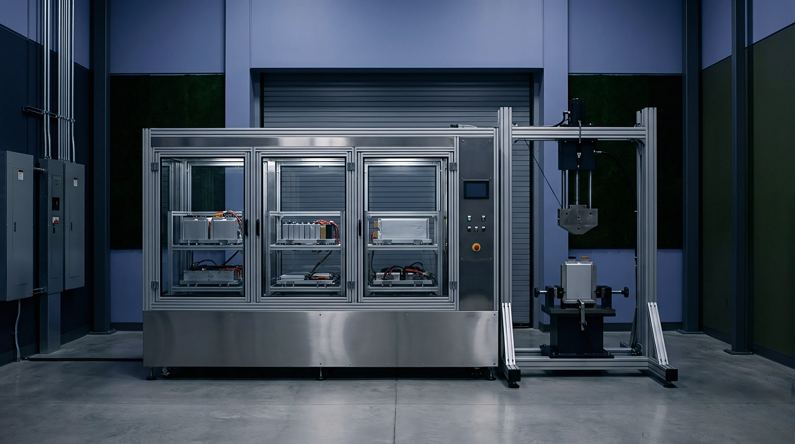
Microstructural Mechanics of Transverse Fracture Propagation
Dynamic impacts generate high strain rates within consolidated high-alloy components. When shock waves traverse the material perpendicular to the consolidation texture, dislocation motion concentrates in narrow zones between inclusion bands. Work hardening within these localized zones cannot keep pace with thermal softening from plastic work, producing adiabatic shear bands within microseconds and establishing through-thickness failure paths.
The severity of microstructural anisotropy traces back to the total hot-work reduction ratio applied after consolidation. Low reduction ratios leave relatively isotropic, low-density prior particle networks with poor overall toughness. High reduction ratios achieve full theoretical density, but they flatten inclusions into continuous transverse planes.
Process design must balance consolidation density against inclusion elongation to preserve transverse impact toughness.
Defect populations in consolidated high-alloy steels follow specific structural failure mechanisms when loaded transverse to their primary processing axis:
- Prior Particle Decohesion occurs along original atomized powder boundaries where residual oxygen forms continuous aluminum oxide or titanium nitride film networks.
- Carbide Stringer Cleavage develops when primary alloy carbides fracture under transverse tension, providing sharp internal starter notches for micro-cracks.
- Sulfide Interface Banding creates low-shear resistance pathways along elongated manganese sulfide inclusions stretched thin during hot reduction passes.
- Untempered Martensite Banding results from local chemical segregation of nickel and molybdenum, causing localized hard embrittled zones during post-weld cooling cycles.
Sub-zero cryogenic stabilization between tempering stages converts retained austenite to martensite, improving yield uniformity. Without subsequent secondary tempering, however, newly formed untempered martensite along segregation bands creates brittle transverse fracture sites. Conditioning protocols must pair deep cryogenic freezing at minus 196 degrees Celsius with triple tempering cycles to ensure complete stress relief across all crystallographic planes.
Aligning material texture vectors with primary impact axes prevents premature transverse shear failures across consolidated alloy battery structures.

Notch
Stress concentrations govern real-world component survival under dynamic fatigue loading. Consolidated steels can achieve yield strengths above 1700 MPa, but higher strength brings heightened sensitivity to notch geometry. Enclosure components inevitably require fastener holes, corner cutouts, tab relief grooves, and laser-weld transitions.
Each geometric discontinuity concentrates operational loads, converting nominal stresses into localized peak tension fields.
Figure 1: Stress Intensity and Crack Growth Rate (dA/dN) Comparison Across Orientations
Linear Elastic Fracture Mechanics (LEFM) mapping for consolidated AerMet 100 high-alloy steel (50 HRC). The chart contrasts crack growth threshold (Δ Kth) and critical fracture toughness (KIc) between longitudinal (L-T) and short-transverse (S-T) grain flow vectors under cyclic impact fatigue.
 Stress Intensity Factor Range ΔK (MPa·m^0.5) 2 5 10 20 40 60 +----------------+---------------+---------------+---------------+--------+
 10^-3 + | | (K_Ic L-T = 52) | / |
 10^-4 + / | | / (L-T Axis)| | / |
 10^-5 + / | | (K_Ic S-T = 28) | # / |
 10^-6 + (ΔK_th L-T = 5.2) # / (S-T Axis) | | # / | | # / |
 10^-7 + # / | | # (ΔK_th S-T = 2.8) / | +-------+----------------+---------------+---------------+--------+ 10^-8 Fatigue Crack Growth Rate dA/dN (mm/cycle)
Linear elastic fracture mechanics governs crack initiation at notches in anisotropic consolidated steels. Critical stress intensity factors drop significantly when crack propagation follows transverse grain boundaries. A sharp notch oriented parallel to the rolling direction exhibits a critical plane fracture toughness of 28 MPa·m1/2, compared to 52 MPa·m1/2 for a longitudinal crack path.
Under equivalent cyclic stress, a transverse notch initiates fatigue cracking in one-fifth the operational cycle count required for a longitudinal notch.
Transverse impact toughness drops abruptly under high strain rates.
Evaluating transient impact loads requires dynamic fracture toughness metrics rather than static KIc values. Fast loading rates shrink the plastic zone at the crack tip, limiting local stress relaxation. In consolidated high-alloy steels with transverse microstructural banding, the dynamic stress intensity threshold for unstable crack propagation drops below 18 MPa·m1/2.
At that level, shallow machining marks or surface scratches inside mounting holes can initiate fatigue cracking during road shock events.
Purchasing documents specifying ASTM A574 compliance without directional toughness addenda release the material supplier from transverse fracture liability.
Consider a structural casing corner bracket subjected to transient road-shock loading. The component is machined from a hot-consolidated PM H13 steel preform hardened to 50 HRC. The bracket carries a nominal cyclic tensile stress of 400 MPa, with an internal corner radius of 1.5 mm creating an elastic stress concentration factor of 2.4.
Peak localized tensile stress reaches 960 MPa at the notch root. The localized stress field calculation uses standard notch mechanics:
σmax = Kt · σnominal = 2.4 · 400,MPa = 960,MPa
When the internal corner root aligns with the longitudinal rolling direction, the fatigue crack initiation threshold stress at the notch root sits at 1100 MPa. The part operates safely within its elastic endurance limits. When machining reorients the bracket such that the internal corner root aligns with the transverse consolidation axis, inclusion stringers lower the localized fatigue crack initiation threshold to 780 MPa.
Peak operational stress exceeds material threshold limits by 180 MPa, causing micro-fatigue initiation within 12,000 vibration test cycles.
| Hardness Level (HRC) | Grain Vector | Notch Radius (mm) | K_t Value | Dynamic K_Id (MPa·m^0.5) | Transverse Fatigue Limit (MPa) |
|---|---|---|---|---|---|
| 48 ± 1 | L-T | 1.0 | 3.1 | 58 ± 3 | 720 ± 20 |
| 48 ± 1 | T-L | 1.0 | 3.1 | 36 ± 2 | 460 ± 15 |
| 48 ± 1 | S-T | 1.0 | 3.1 | 24 ± 2 | 310 ± 15 |
| 52 ± 1 | L-T | 1.0 | 3.1 | 52 ± 3 | 680 ± 20 |
| 52 ± 1 | T-L | 1.0 | 3.1 | 31 ± 2 | 410 ± 15 |
| 52 ± 1 | S-T | 1.0 | 3.1 | 19 ± 1.5 | 260 ± 10 |
| 56 ± 1 | L-T | 1.0 | 3.1 | 44 ± 2 | 590 ± 25 |
| 56 ± 1 | T-L | 1.0 | 3.1 | 22 ± 1.5 | 330 ± 15 |
| 56 ± 1 | S-T | 1.0 | 3.1 | 13 ± 1.0 | 190 ± 10 |
Dynamic shock loading demands isotropic resistance throughout the section.
Electrical discharge machining (EDM) used to cut tight-tolerance tab features leaves a recast surface layer filled with micro-cracks. In high-alloy consolidated steels, this heat-affected recast layer contains untempered martensite and high tensile residual stress. When the recast layer sits on a transverse material plane, micro-cracks propagate immediately into the bulk interior under low-amplitude vibration.
Machining specifications for structural battery components must mandate complete removal of the EDM recast layer via chemical etching or CNC polishing.
Omitting grain direction alignment relative to the main mounting notch plane on drawing notes specifying corner radius tolerances resulted in a thirty-eight thousand dollar scrap cost on a pilot enclosure run.

Fatigue
Cyclic fatigue limits govern long-term structural integrity in electric vehicle battery packs. Vehicles endure millions of low-amplitude flexural vibration cycles over their operating lifespan, alongside intermittent high-amplitude shock events caused by road debris or rough terrain. Accelerated mechanical lifecycle profiles under ISO 16750-3 subject battery module enclosures to random multi-axis vibration profiles spanning 10 Hz to 2000 Hz. Structural members must resist fatigue initiation across all geometric axes.
Transverse fatigue limits fall well below longitudinal baselines.
In high-alloy consolidated steels, high-cycle fatigue performance demonstrates extreme anisotropy. Longitudinal endurance limits (Se,L) typically reach 45 to 50 percent of ultimate tensile strength. Transverse endurance limits (Se,T) frequently drop to 20 to 30 percent of ultimate tensile strength.
When internal pack components experience complex torsional twisting, transverse tension stress components rapidly induce micro-crack nucleation along inclusion stringers.
Charpy V-notch energy drops from 48 Joules in the longitudinal direction down to 14 Joules in the short-transverse direction for consolidated maraging alloy grade 350 at 52 HRC.
Mean stress correction models like Goodman or Morrow relationships highlight how vulnerable transverse material vectors are under sustained mechanical pre-loads. Fastener torque, thermal expansion of battery cells during fast charging, and structural module clamping force introduce high static tensile mean stress (σm). High mean stress combined with cyclic vibration (σa) shifts the operating point into non-linear fatigue degradation regimes.
Transverse grain vectors exhibit accelerated sensitivity to mean stress elevation, drastically shrinking allowable cyclic stress amplitude.
Inclusions act as micro-stress raisers within the consolidated matrix.
Surface micro-topography interacts with microstructural directionality to set real-world component fatigue strength. Shot peening introduces compressive residual surface stress, elevating fatigue limits by delaying crack initiation. Its efficacy depends directly on subsurface inclusion density.
If shot peening drives compressive stresses into a layer containing elongated transverse inclusions, micro-cracks initiate beneath the compressed surface zone. Non-destructive quality checks must verify micro-cleanliness ratings prior to surface treatment operations.
Manufacturing process specifications for high-alloy consolidated components follow precise steps to mitigate transverse fatigue failures during serial production:
- Map primary cyclic stress vectors across the structural enclosure assembly using transient dynamic finite element models.
- Orient raw consolidated billet stock during nesting setup so that transverse grain axes align with minimal operational stress directions.
- Perform rough CNC machining while leaving 0.5 mm surface stock on all high-stress notch profiles and mounting radii.
- Apply vacuum stress-relief heat treatment at 550 degrees Celsius for two hours to neutralize machining-induced surface stress fields.
- Execute fine finishing passes using diamond-coated tooling to eliminate micro-grooves perpendicular to the consolidation flow vector.
- Perform controlled wet glass-bead shot peening at an Almen intensity of 0.008 A to induce isotropic compressive surface stress without distorting wall dimensions.
Surface finish alters cyclic endurance across all stress axes.
Attributing premature fatigue fractures on structural tie-rods entirely to random road vibration overlooks how microstructural orientation lowers baseline S-N thresholds.

Validation
Verification protocols must capture directional material properties before raw consolidated steel enters finished component production. Standard mill test certificates reporting basic longitudinal tensile data do not provide adequate risk coverage for safety-critical battery pack structures. Comprehensive material qualification protocols demand destructive dynamic impact testing and non-destructive ultrasonic defect evaluation across all three principal material axes.

What Destructive Criteria Govern Transverse Fracture Acceptance?
Destructive verification mandates Charpy V-notch impact testing performed according to ASTM E23 standards using specimens cut specifically in L-T, T-L, and S-T orientations. Minimum acceptable energy absorption limits must be enforced for each orientation separately. For consolidated high-alloy steels operating in battery crash enclosures, the short-transverse impact energy at minus 40 degrees Celsius must exceed 15 Joules, and the ratio of transverse-to-longitudinal impact energy must remain above 0.55.
Lots failing this ratio indicate excessive inclusion stringering or incomplete powder particle bonding during hot isostatic consolidation.
Non-destructive evaluation (NDE) of consolidated raw stock requires high-frequency phased-array ultrasonic testing (PAUT) per ASTM E2375. Standard single-element ultrasonic probes miss thin, planar transverse inclusion bands aligned parallel to the sound beam axis. Phased-array probes steer sound waves across multiple angles, detecting planar defects oriented parallel to rolling planes.
Acceptance standards must reject raw billets containing planar inclusion indications larger than 0.2 mm equivalent side-drilled hole diameter.
| NDE Inspection Method | Defect Orientation Target | Minimum Detection Limit (mm) | Critical Crack Size Transverse (mm) | Production Line Takt Impact |
|---|---|---|---|---|
| Standard Ultrasonic (10 MHz) | Volumetric Voids / Porosity | 0.8 ± 0.1 | 1.2 | Inline / 15 sec per billet |
| Phased-Array Ultrasonic (PAUT) | Planar Transverse Inclusion Bands | 0.15 ± 0.02 | 0.45 | Offline / 3 min per billet |
| X-Ray Micro-Computed Tomography | Prior Particle Oxide Networks | 0.02 ± 0.005 | 0.20 | Batch Sampling / 45 min per bar |
| Fluorescent Magnetic Particle | Surface Micro-Cracks at Notches | 0.05 ± 0.01 | 0.15 | Inline / 20 sec per part |
| Acoustic Emission Proof Load | Active Dynamic Crack Propagation | 0.01 ± 0.002 | 0.10 | Inline / 40 sec per assembly |
Material qualification demands directional specimen testing across all axes.
Receiving inspection procedures for consolidated high-alloy steel stock rely on explicit quality verification clauses inserted directly into global procurement contracts:
- Directional Toughness Mapping requires mill test reports to include Charpy V-notch energy figures for both longitudinal and transverse sample orientations per production heat.
- Micro-Cleanliness Verification enforces ASTM E45 Method A rating limits, capping thin-series sulfide, alumina, silicate, and globular oxide inclusions at rating 0.5 maximum.
- Consolidation Density Compliance mandates liquid displacement density testing per ASTM B962, requiring minimum relative density of 99.95 percent of theoretical solid density.
- Prior Particle Boundary Assessment requires metallographic micro-etching using Murakami’s reagent to verify complete absence of continuous carbide networks at prior particle interfaces.
Uniaxial data disguises transverse failure risk under multiaxial operating loads.
Acoustic emission monitoring during mechanical proof testing provides real-time verification of structural integrity in fully assembled pack frames. As the frame experiences simulated maximum torsional load, piezoelectric sensors detect acoustic stress waves emitted by micro-crack initiation events. Transverse inclusion decohesion emits distinct high-amplitude pulse frequencies between 100 kHz and 300 kHz long before visible plastic yield occurs.
Detecting acoustic activity during proof loads permits early rejection of defective frames before expensive cell integration steps occur.
Cold work accumulated during deep drawing transforms residual austenite into untempered martensite along transverse corners.
Under Section 8.3 of standard automotive raw material procurement agreements, a buyer who accepts steel stock based on passing longitudinal tensile certification waives all financial recourse against the consolidator for subsequent transverse splitting during component stamping operations.

Fulfillment
Scrap rates escalate quickly without tight orientation controls.
Tooling wear accelerates along transverse planes during machining operations.
Financial viability in high-alloy consolidated steel procurement depends on managing scrap rates, tooling Non-Recurring Engineering (NRE) costs, and warranty liability boundaries across the supply chain. Powder metallurgical hot isostatic pressing and high-alloy vacuum melting carry raw material price tags ranging from 18 to 45 USD per kilogram. Machining structural pack components from solid consolidated billets generates significant scrap volumes, pushing finished component cost multipliers above 4.0 relative to raw stock price.
Consolidated steel preforms pressed close to final component geometry reduce machining scrap and preserve favorable external surface consolidation boundaries. Near-net-shape HIP tooling requires substantial upfront investment, with die sets ranging from 120,000 to 350,000 USD depending on geometric complexity. Amortizing NRE costs over production volumes requires minimum contract commitments of 15,000 unit assemblies.
Buyers must calculate the break-even volume where near-net-shape tooling NRE offsets the high material waste of machining solid billet stock.
Figure 2: Landed Unit Cost Sensitivity to Scrap Rate and Consolidation Material Yield
Financial model mapping finished component landed cost (USD/kg) against raw material scrap rate across three production strategies: Solid Billet CNC Machining, Forged Preform Machining, and Near-Net-Shape HIP Consolidation.
Finished Part Cost (USD/kg) 160 + / (Solid Billet) | / 140 + / | / (Forged Preform) 120 + / | / 100 + / | / # (Near-Net HIP) 80 + / # | / # 60 + / # +-----------------+-----------------+-------------+--+----+------------------+ 10% 20% 30% 40% 50% 60% Raw Material Scrap Rate (%)
Quality dispute resolution boundaries between the powder consolidator, component stamper, and battery pack integration house require explicit definition inside the supply contract. If a component splits along a transverse inclusion band during cold stamping, responsibility hinges on whether raw material cleanliness met contractual ASTM E45 limits or whether stamper die clearance exceeded allowable drawing tolerances. Splitting warranty liability into clear, verifiable test parameters prevents stalled supply lines when component defects surface on serial production lines.
Landed cost calculations must incorporate duty rates, transport hazard classifications, and directional material qualification compliance auditing. Consolidated high-alloy steels containing over 10 percent nickel or cobalt incur specific tariff sub-headings (such as HS Code 7228.10 or 7228.40) carrying import duty rates between 3.5 and 7.5 percent depending on cross-border trade corridors. Scrap generated by transverse material splitting on the component stamping line cannot be reclaimed at full alloy value; local scrap recyclers pay less than 15 percent of original powder material cost due to the complex recycling metallurgy of multi-element high-alloy systems.
Direct supply agreements with powder consolidation mills specify raw billet ultrasonic testing standards, certified Charpy V-notch energy minimums in both L-T and S-T vectors, and strict maximum allowable primary inclusion sizes. Incorporating these directional mechanical parameters into initial RFQ documentation forces material vendors to optimize their hot isostatic compaction and rolling cycles for isotropic strength. Aligning procurement specifications with real-world dynamic stress vectors ensures that high-alloy consolidated components deliver their full theoretical load capacity without brittle transverse fracture during battery pack operation.