Combustible Gas Exhaust Volumetric Flow Rates and Deflagration Control in High Density Containerized Enclosures
Engineering high density battery enclosures requires sizing active exhaust rates to peak off-gas evolution and NFPA 68 vents to hydrogen-rich deflagration indices.

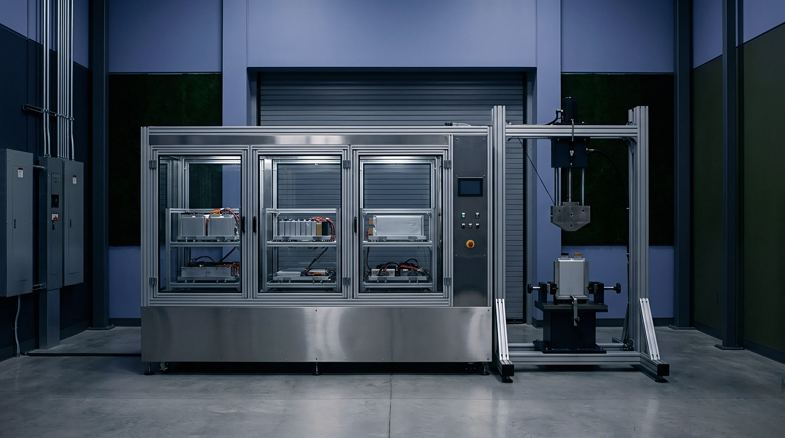
Offgassing
In high-density energy storage enclosures, thermal runaway converts solid cell materials into high-velocity gas streams. Crossing thermal breakdown thresholds triggers rapid reactions among liquid organic carbonate solvents, lithium salts, and cathode metal oxides. Peak release rates depend heavily on state of charge, cell chemistry, and heat transfer speed through cell walls.
Standard 300 Ah lithium iron phosphate cells release 80 to 140 liters of gas per kilowatt hour of nominal capacity during full thermal runaway, whereas high-nickel ternary NMC cells under identical conditions generate between 150 and 260 liters per kilowatt hour. Exiting at temperatures from 350 degrees Celsius to over 800 degrees Celsius, this gas carries aerosolized electrolyte droplets, conductive carbon particles, and heavy metal oxides.
Calculating total gas volume requires exact composition modeling. As cell voltage drops and moisture reacts with exposed lithium or graphite anodes, hydrogen quickly becomes a major constituent. The remaining volume consists of carbon monoxide, carbon dioxide, methane, ethylene, and vaporized dimethyl carbonate.
Higher states of charge skew the mixture toward hydrogen and carbon monoxide over carbon dioxide: an LFP cell at 100 percent state of charge produces an effluent stream containing up to 35 percent hydrogen by volume, compared to less than 15 percent hydrogen at 50 percent state of charge. These compositional shifts adjust the lower flammability limit and alter operational thresholds for active exhaust equipment.
The composition of thermal runaway gas changes continuously across the temperature profile of cell destruction.
Cell venting produces sharp spikes in flow rate. Initial off-gassing causes a modest pressure rise as current interrupt devices or safety vents operate, but full casing rupture creates an immediate volumetric surge. A single 300 Ah cell can exceed peak flow rates of 20 liters per second within 500 milliseconds of rupture.
When failure cascades across multiple modules, generation multiplies into massive flow spikes. An unmitigated failure in a 5 megawatt-hour containerized system produces peak volumetric flow rates above 12 cubic meters per second. Designing exhaust systems around average release rates guarantees rapid enclosure overpressurization.
Pressure build-up in standard ISO freight containers presents a severe structural threat: side walls begin deflecting at internal overpressures as low as 5 kilopascals, and structural seams fail near 20 kilopascals. Exhaust capacity must stay ahead of peak off-gassing rates to keep internal pressure safely below wall yield limits. Calculating off-gas kinetic rates establishes baseline fan response windows.
If fan extraction fails to match peak gas evolution, the enclosure will rupture during early propagation.

Gas Yield Mechanisms across Failure States
Internal short circuits from separator breakdown generate localized ohmic heating. Above 110 degrees Celsius, electrolyte solvents start vaporizing into modest volumes of low-boiling-point carbonates, while solid electrolyte interphase breakdown releases trace carbon dioxide and oxygen. As temperatures rise further, cathode degradation releases structural oxygen directly into the cell cavity.
This breakdown occurs between 160 and 210 degrees Celsius in NMC chemistries depending on nickel fraction, whereas LFP phase stability delays oxygen release until temperatures clear 270 degrees Celsius. Internal pressure continues climbing until safety vents open.
Vent activation prompts rapid thermodynamic expansion of accumulated gases and vaporized solvents. Sudden depressurization aerosolizes liquid electrolyte into fine droplets, dramatically increasing reactive surface area. Meanwhile, fluorine-bearing lithium salts react with moisture in the air or ductwork to generate hydrofluoric acid.
Release mechanics accelerate across four distinct stages:
- Initial Outgassing Phase involves modest internal pressure build-up, slow solvent evaporation, and low-flow discharge through cell relief valves prior to full runaway.
- Primary Cell Venting marks full opening of internal cell caps, discharging high-velocity electrolyte vapor, rapid carbon dioxide evolution, and entrained liquid droplets.
- Thermal Runaway Ignition brings rapid chemical breakdown of cathode material, fast hydrogen synthesis, and sudden expansion of volatile hydrocarbons.
- Cascading Propagation Stage transfers heat conductively and radiatively to neighboring cells, driving exponential gas volume growth across battery racks.
Peak volumetric flow rates correlate directly with propagation speed. In dense modules, fast thermal spread causes individual gas release curves to overlap. Narrow gaps between cells restrict thermal dissipation, accelerating runaway to adjacent units.
Inserting passive insulation barriers between cells slows this transfer, distributing total gas output across a longer timeframe and reducing the peak flow rate the ventilation system must handle.
Gas composition evolves as failure progresses. Early emissions consist primarily of carbon dioxide and evaporated solvents, but later off-gas generated at elevated core temperatures carries high concentrations of hydrogen and carbon monoxide. Hydrogen has a wide flammability range (4 to 75 percent in air) and a minimal ignition energy of just 0.02 millijoules.
Elevated hydrogen levels shift the primary explosion hazard inside unvented enclosures from subsonic deflagration toward violent detonation. Safety systems must account for these shifting chemical ratios across the entire failure timeline.
Underestimating peak volumetric off-gas flow rates leads directly to enclosure structural collapse, flame jetting through unrated seams, and dangerous external gas accumulation.


Ventilation
Active ventilation systems keep combustible gas concentrations safely below lower flammability limits during off-gassing events. Design calculations focus on determining the minimum purge flow rate required to dilute released species quickly. NFPA 69 establishes standard formulas for explosion prevention via continuous dilution, while NFPA 855 mandates active ventilation hardware for indoor and containerized lithium-ion sites.
Mandatory safety thresholds cap combustible gas levels at 25 percent of the lower flammability limit during manned access, and 50 percent during automated, unoccupied operation.
Determining dilution flow requirements begins with calculating the lower flammability limit of the composite gas mixture. Because off-gas contains multiple flammable species, Le Chatelier’s mixing rule is used to find the effective flammability threshold. This calculation combines volume fractions and limits for hydrogen, carbon monoxide, methane, ethylene, and vaporized solvents.
Dimethyl carbonate and similar solvents have lower flammability limits near 4.2 percent by volume, while hydrogen sits at 4.0 percent. For standard LFP off-gas, composite limits typically fall between 6.0 percent and 8.5 percent concentration in air.

Required Volumetric Flow Rate Calculations
Sizing active dilution systems requires solving continuous mass balance equations across the enclosure volume. Total required airflow depends on peak gas release rates, target flammability limits, net enclosure volume, and internal mixing efficiency. Ventilation efficiency factors compensate for dead zones within dense rack structures, where physical obstructions disrupt airflow and allow gas to pool despite high nominal exchange rates.
Establishing final design flow rates involves applying safety factors to peak off-gas rates measured during testing. The core mass balance equation governing combustible gas concentration in a ventilated space follows a standard dynamic dilution model:
C(t) = (G / Q) (1 – exp(-k Q t / V))
Here C represents gas volume concentration, G is volumetric gas generation rate, Q is total exhaust flow rate, V is net free volume, k is the mixing efficiency factor (typically 0.35 to 0.70 in dense battery installations), and t is time. Setting terminal concentration C to 25 percent of the composite lower flammability limit determines the minimum flow rate Q needed for compliance.
| Gas Component | Volume Fraction Range (%) | Lower Flammability Limit (% Vol) | Upper Flammability Limit (% Vol) | Stoichiometric Ratio in Air (%) |
|---|---|---|---|---|
| Hydrogen (H2) | 20 – 38 | 4.0 | 75.0 | 29.5 |
| Carbon Monoxide (CO) | 22 – 42 | 12.5 | 74.0 | 29.5 |
| Carbon Dioxide (CO2) | 15 – 35 | Non-flammable | Non-flammable | N/A |
| Methane (CH4) | 3 – 10 | 5.0 | 15.0 | 9.5 |
| Ethylene (C2H4) | 2 – 8 | 2.7 | 36.0 | 6.5 |
| Electrolyte Vapors | 5 – 18 | 1.8 – 4.2 | 11.0 – 16.0 | 3.2 – 4.8 |
Variable-speed exhaust fans tied to gas detection networks minimize standby parasitic power draw while maintaining rapid response. Sample lines drawing air from high-risk pooling points above battery racks feed non-dispersive infrared sensors and electrochemical hydrogen detectors. Gas detection ramps fans to full capacity within 2 seconds.
Total system latency ~ combining sensor response, signal processing, motor acceleration, and damper actuation ~ must remain shorter than the time it takes local gas pockets to hit the lower flammability limit.
A continuous purge rate of four air changes per hour maintains baseline air quality, but emergency purge modes require exceeding sixty air changes per hour during off-gas events.
Ventilation design must balance climate control against safety extraction. HVAC equipment recirculates internal air for energy efficiency, but emergency ventilation demands continuous, open-loop exhaust during off-gas events. Upon gas detection, motorized isolation dampers immediately shut off recirculating loops and switch exhaust units to full fresh-air extraction.
Duct velocities during emergency operation must exceed 15 meters per second to prevent explosive gas from stratifying along ceiling surfaces.
Determining emergency purge flow rates follows a structured engineering workflow:
- Obtain peak volumetric off-gas generation rates from UL 9540A unit-level test data across worst-case propagation scenarios.
- Calculate the composite lower flammability limit using Le Chatelier’s equation and measured gas species fractions.
- Define the enclosure safety threshold, capping allowable gas concentration at 25 percent of the composite limit.
- Calculate net free volume by subtracting space occupied by racks, inverters, transformers, and structural components from gross enclosure dimensions.
- Apply a mixing efficiency coefficient derived from CFD modeling to account for dead zones in tight rack layouts.
- Solve the dynamic mass balance equation for the minimum required exhaust flow rate.
- Select fan equipment capable of delivering design flow against total system backpressure from ductwork, dampers, and weather hoods.
Airflow distribution in dense enclosures depends heavily on intake placement. Low-mounted intake louvers establish an upward sweeping path through battery racks toward ceiling exhaust ducts. This bottom-to-top flow profile prevents gas from pooling under module shelves.
Recessed structural channels and wiring troughs need dedicated extraction taps to avoid localized gas accumulation.
Effective airflow design eliminates dead zones where combustible gases might otherwise gather undetected despite adequate overall air exchange rates.


Deflagration
Combustible gas clouds inside closed battery enclosures pose severe deflagration risks if ignited before ventilation dilutes concentrations. Deflagration is subsonic combustion where an advancing flame front compresses unburned gas ahead of the reaction zone, driving rapid pressure spikes. Unvented deflagrations in standard shipping containers can produce peak explosion pressures over 8 bar absolute ~ more than forty times the structural rating of standard container walls and doors.
NFPA 68 governs the design of deflagration venting systems built to safely release internal pressure. These systems use low-mass panels, explosion doors, or pressure-sensitive membrane seals set to open at specific thresholds. Actuation opens a relief path that exhausts expanding combustion products and unburned gas to the outside.
Proper vent sizing caps maximum internal pressure at a target reduced pressure level, which must remain well below the enclosure’s structural yield limit.

Mathematical Modeling of Explosion Vent Areas
Sizing explosion relief panels requires knowing the deflagration index (K_g) of the off-gas mixture, which measures the maximum rate of pressure rise in a closed 1 cubic meter sphere under standard test conditions. Hydrogen-rich mixtures produce high K_g values: while typical hydrocarbon gases fall between 50 and 100 bar·m/s, pure hydrogen reaches 550 bar·m/s. Off-gas from high state-of-charge lithium-ion batteries generally yields K_g values from 110 to 180 bar·m/s, classifying the mixture under NFPA 68 Explosion Class St-2 or Gas Group IIB+H2.
NFPA 68 low-strength enclosure formulas apply when target reduced pressure stays at or below 0.2 bar gauge. Calculating required vent area depends on internal surface area, volume, fundamental burning velocity, panel deployment pressure, and allowable reduced pressure, using standard empirical relationships:
A_v = (C_1 A_s P_max) / (P_red^0.5 K_g^0.5)
In this equation, A_v is required vent area in square meters, A_s is internal surface area, P_max is maximum unvented pressure, P_red is allowable reduced pressure, and C_1 is an empirical constant combining gas density and burning velocity. Higher K_g values sharply increase required vent area, frequently exceeding available wall or roof area on dense container layouts.
| Parameter Description | Symbol | Value Baseline | High Hydrogen Scenario | Units |
|---|---|---|---|---|
| Gross Enclosure Volume | V | 38.5 | 38.5 | m³ |
| Net Free Volume | V_net | 26.2 | 26.2 | m³ |
| Enclosure Yield Pressure | P_yield | 0.15 | 0.15 | bar g |
| Target Reduced Pressure | P_red | 0.10 | 0.10 | bar g |
| Vent Deployment Pressure | P_stat | 0.02 | 0.02 | bar g |
| Deflagration Index | K_g | 120 | 175 | bar·m/s |
| Maximum Explosion Pressure | P_max | 7.8 | 8.6 | bar g |
| Calculated Vent Area | A_v | 2.45 | 3.82 | m² |
The sensitivity of vent sizing to variations in the deflagration index demands rigorous validation. Sensitivity modeling across typical BESS volumes demonstrates how gas composition shifts impact required vent geometries. For example, a 20-foot container with a net free volume of 26.2 cubic meters requires 2.45 square meters of vent area under baseline LFP off-gas assumptions.
If thermal runaway occurs at 100 percent state of charge and high temperatures push hydrogen content to 38 percent by volume, composite K_g rises from 120 to 175 bar·m/s, driving required vent area to 3.82 square meters. If roof space accommodates only 2.50 square meters of venting, internal pressure during a deflagration will peak at 0.18 bar gauge ~ exceeding the 0.15 bar gauge wall yield limit and tearing structural seams.
Managing deflagration hazards often means pairing passive vents with active suppression systems. Active deflagration suppression injects fast-acting agents directly into the space upon detecting early flame kernels. Dry chemicals like sodium bicarbonate or liquid clean agents can quench reaction fronts within 50 milliseconds, arresting pressure development before internal stresses trigger physical vent deployment.
Roof-mounted vent panels discharge thermal plumes upward, protecting adjacent battery units and access paths. Side-wall venting risks exposing neighboring containers in dense layouts to direct flame contact and radiant heat; consequently, NFPA 855 enforces strict separation distances when side venting is used. Roof vents rely on low-mass construction ~ such as insulated polyisocyanurate cores with thin aluminum skins ~ that releases cleanly at activation pressures as low as 2 kilopascals.
If relief ducts carry vent effluent away from the enclosure, dynamic pressure calculations must account for duct inertia. Adding discharge ducting increases internal reduced pressure due to gas mass and frictional backpressure. NFPA 68 supplies adjustment factors for duct length; runs longer than 3 meters generally require significantly larger vent panels or reinforced container walls to handle the elevated pressure.
Inerting provides another route for deflagration control under NFPA 69. Continuous or demand-triggered nitrogen injection lowers internal oxygen below the limiting oxygen concentration needed for combustion ~ roughly 8.5 percent by volume for off-gas mixtures containing hydrogen and carbon monoxide. Keeping oxygen below this threshold prevents ignition regardless of combustible gas concentration, though high off-gas flow rates can rapidly displace nitrogen, requiring substantial storage banks to sustain inert conditions during cooling.
Does active inerting fully remove the requirement for passive deflagration relief panels in high density containerized systems?


Certification
Demonstrating regulatory compliance for energy storage enclosures demands physical testing alongside documentation review. UL 9540A is the benchmark test standard for evaluating thermal runaway fire propagation in BESS hardware. Its test reports provide the empirical data ~ gas composition, peak generation rates, and flame dynamics ~ needed to size exhaust systems and design deflagration controls.
UL 9540A evaluation moves through four structural tiers: cell, module, unit, and installation level. Cell testing drives a single unit into runaway via heating or puncture, measuring gas volume, composition, release rate, and flammability limits. Module testing checks whether runaway spreads to adjacent cells within a pack frame.
Unit-level testing evaluates full rack and container configurations, recording gas generation rates, temperature rise, and external flaming under realistic installation conditions.

Is Standardized Test Data Scalable to High Density Formats?
Extrapolating cell-level UL 9540A data to full container scale poses real engineering difficulties. An isolated cell in a laboratory pressure vessel does not behave like thousands of densely packed cells in a field enclosure. In complete modules, nearby thermal mass, restricted gas expansion paths, and structural framing alter heat flow and peak gas kinetics, requiring scaling models to account for multi-rack propagation dynamics.
| UL 9540A Test Tier | Extracted Test Parameter | Primary Measurement Units | Engineering Application Target |
|---|---|---|---|
| Cell Level | Total Gas Volume (V_gas) | Liters per Ah (L/Ah) | Total enclosure gas accumulation modeling |
| Cell Level | Gas Species Breakdown | Volume Percentage (% Vol) | Composite LFL and K_g calculation |
| Cell Level | Maximum Deflagration Pressure | bar gauge (bar g) | NFPA 68 vent panel sizing baseline |
| Module Level | Propagative Heat Transfer Rate | Watts (W) or °C/sec | Inter-cell thermal barrier specification |
| Module Level | Peak Off-Gas Volumetric Rate | Liters per second (L/s) | Emergency fan dynamic response sizing |
| Unit Level | Re-ignition Propensity | Time to ignition (seconds) | Purge duration and fan runtime parameters |
| Unit Level | External Flame Profile | Plume length and flux (m, kW/m²) | Container inter-unit separation distance |
Compiling a reliable safety dossier requires matching certified test parameters to actual field conditions. Vendor datasheets frequently cite tests run at 50 or 80 percent state of charge to show favorable safety figures. Sourcing engineers must ensure UL 9540A summaries reflect 100 percent state of charge, which governs peak gas volume and hydrogen content.
Laboratory reports should clearly state test methods, trigger mechanisms, ambient pressure, and gas sampling protocols.
International transit regulations mandate strict safety documentation before cells can be shipped. UN 38.3 test summaries verify cell stability under thermal exposure, vibration, shock, short circuit, impact, overcharge, and forced discharge. Section 38.3.5 of the UN Manual of Tests and Criteria defines the required single-page summary format.
Although UN 38.3 does not measure off-gas volume, it proves the basic structural integrity required for dangerous goods transit under UN 3480.
Shipping paperwork must match physical cargo details exactly. Port forwarders cross-check test summary serial numbers against manifests; a simple discrepancy in cell model suffixes between the UL 9540A report and physical serial numbers causes immediate customs holds and port rejection. Procurement contracts should require vendors to supply unredacted UL 9540A reports and UN 38.3 summaries before releasing milestone payments.
Supply contracts must clearly define the boundaries of test coverage. Vendor agreements frequently contain disclaimers that void test validity if integrators modify rack spacing, fan selection, or enclosure insulation. Altering the internal layout invalidates unit-level UL 9540A approvals, shifting full regulatory and structural liability onto the integrator.
The standard procurement supply agreement must contain explicit language binding cell test reports to delivered battery lots:
Section 14.2 Certification Integrity Clause ~ The Seller warrants that all UL 9540A unit level test reports, gas composition analyses, and peak volumetric flow rate data supplied to Buyer accurately represent the exact cell chemical formulation, state of charge capability, and mechanical module geometry delivered under this purchase order. Any modification to cell cathode stoichiometry, electrolyte additive mix, internal cap vent release pressure, or module structural packing density executed without Buyer prior written consent shall immediately void safety compliance acceptances and place full financial liability for recertification, redesign, and site approval delays upon the Seller.
Duct
Exhaust manifold design governs actual gas clearance performance in the field. Theoretical airflow rates calculated from mass balances mean little if duct geometry introduces high fluid friction or backpressure. Smooth interior surfaces, generous bend radii, and clean transitions preserve airflow and prevent static pressure build-up.
Continuous-welded stainless steel provides necessary structural strength and resists corrosive species like hydrofluoric acid.
Ductwork must survive severe thermal shocks and direct flame exposure during discharge. Off-gas streams reaching 600 degrees Celsius quickly destroy standard galvanized coatings and flexible expansion joints. Manifolds inside battery compartments typically require at least 10-gauge 316L stainless steel, while external runs need fire-resistant insulation jackets rated for 2-hour internal or external fire exposure under ASTM E119.
In-line flame arrestors prevent external ignition sources from flashing back into the enclosure. Static charges, lightning, or nearby flames at discharge outlets can ignite exiting gas plumes. Detonation arrestors use crimped metal ribbon elements to quench advancing flames through rapid heat transfer in narrow passages.
Choosing an arrestor requires balancing quenching capability against pressure drop: high-efficiency units add significant flow resistance and can reduce fan output by up to 35 percent if undersized.
Exhaust fans must meet explosion-proof ratings for hazardous locations. Handling hydrogen-bearing off-gas requires ATEX Zone 1 or Class I, Division 1, Group B compliance. AMCA Standard 99 Type A spark-resistant construction mandates non-ferrous components in the airstream, including cast aluminum impellers and copper inlet rings.
Mounting direct-drive motors outside the primary air stream eliminates belt-slip ignition hazards and shaft seal leakage.
Designing effective duct networks requires evaluating components against key operational stresses:
- Stainless Steel Manifolds withstand high temperatures and hydrofluoric acid corrosion while maintaining pressure-tight seals during pressure surges.
- Crimped Metal Flame Arrestors quench advancing flame fronts in narrow channels, though they require pressure-drop monitoring to guard against soot build-up.
- Explosion-Proof Direct-Drive Fans deliver continuous spark-resistant extraction without belt failure points or shaft packing leaks.
- Motorized Isolation Dampers isolate HVAC cooling loops during emergency extraction, preventing toxic gas from backing up into adjacent bays.
- Roof Discharges with Counter-Balanced Weather Hoods direct toxic exhaust vertically away from walkways, opening under low fan discharge pressure.
Backpressure in long duct runs cuts into real-world fan performance. As system static pressure climbs along the fan curve, delivered airflow drops. Pressure calculations must tally losses from straight runs, elbows, junctions, dampers, flame arrestors, and discharge hoods.
If total backpressure exceeds fan capabilities, exhaust volume falls short and combustible gas levels can cross flammability thresholds.
Supplier installation manuals highlight a common oversight: “The supplied exhaust fan achieves specified volumetric capacity under open inlet conditions, but connecting external customer ductwork invalidates flow ratings unless overall friction losses remain below 50 Pascals.” Integrators who ignore duct backpressure run the risk of operating underpowered extraction systems during off-gas events.

Liability
Overpressure incidents, toxic gas releases, and container deflagrations carry immense financial and legal exposure for developers, integrators, and asset owners. Regulators strictly enforce safety standards; non-compliance risks shutdown orders, invalidated property insurance, and heavy litigation following an incident. Securing approval under NFPA 855 requires a detailed Safety Analysis Report documenting off-gas management, exhaust calculations, and deflagration controls.
Insurance underwriters closely inspect BESS sites when evaluating property damage and business interruption risks. Current guidelines mandate proof that container safety hardware aligns with NFPA 68, NFPA 69, and UL 9540A test data. Insurers frequently invoke policy exclusions if an integrator cannot prove exhaust capacity matches peak off-gas generation rates.
An uninsured total loss at a 100 megawatt-hour facility can easily exceed forty million dollars in direct replacement costs.
Engineering Justification Reports form the core defense for non-standard container designs. When spatial constraints prevent installing full NFPA 68 vent areas, integrators must submit an engineering justification to the local Authority Having Jurisdiction. The filing relies on CFD simulations and reaction kinetics to demonstrate that alternative approaches ~ like ultra-fast inerting or high-velocity dilution ~ provide equivalent protection.
Approval rests entirely at the discretion of the local authority.
EPC contracts center heavily on performance guarantees for safety sub-systems. Integrators often try to push deflagration liability back to cell suppliers by attributing thermal runaway to manufacturing defects. However, vendor warranties typically cover only cell replacement costs and exclude consequential damages from fires or container deflagrations.
The legal responsibility for properly sizing ventilation and pressure relief systems rests firmly on the integrator.
Site Acceptance Testing validates safety hardware before commercial operation starts. Commissioning protocols require pitot-tube duct traverses to verify fan flow rates, timing tests for damper response under alarm conditions, and physical inspection of vent panel release mechanisms. Signed acceptance records form a critical part of the asset transfer file, protecting engineering firms against subsequent operational claims.
Project financing relies heavily on clean safety sign-offs. Infrastructure lenders and equity partners hold back funding until independent engineers confirm that exhaust sizing and deflagration controls meet regional fire codes. Building a thorough compliance dossier early in design protects draw-down schedules and safeguards long-term asset viability.