Quantifying Helium Leak Rates for Commercial Pouch Cell Quality Control
Helium leak quantification below 1e-6 mbar L/s requires background suppression, flow conversion modeling, and strict pouch heat seal quality control.

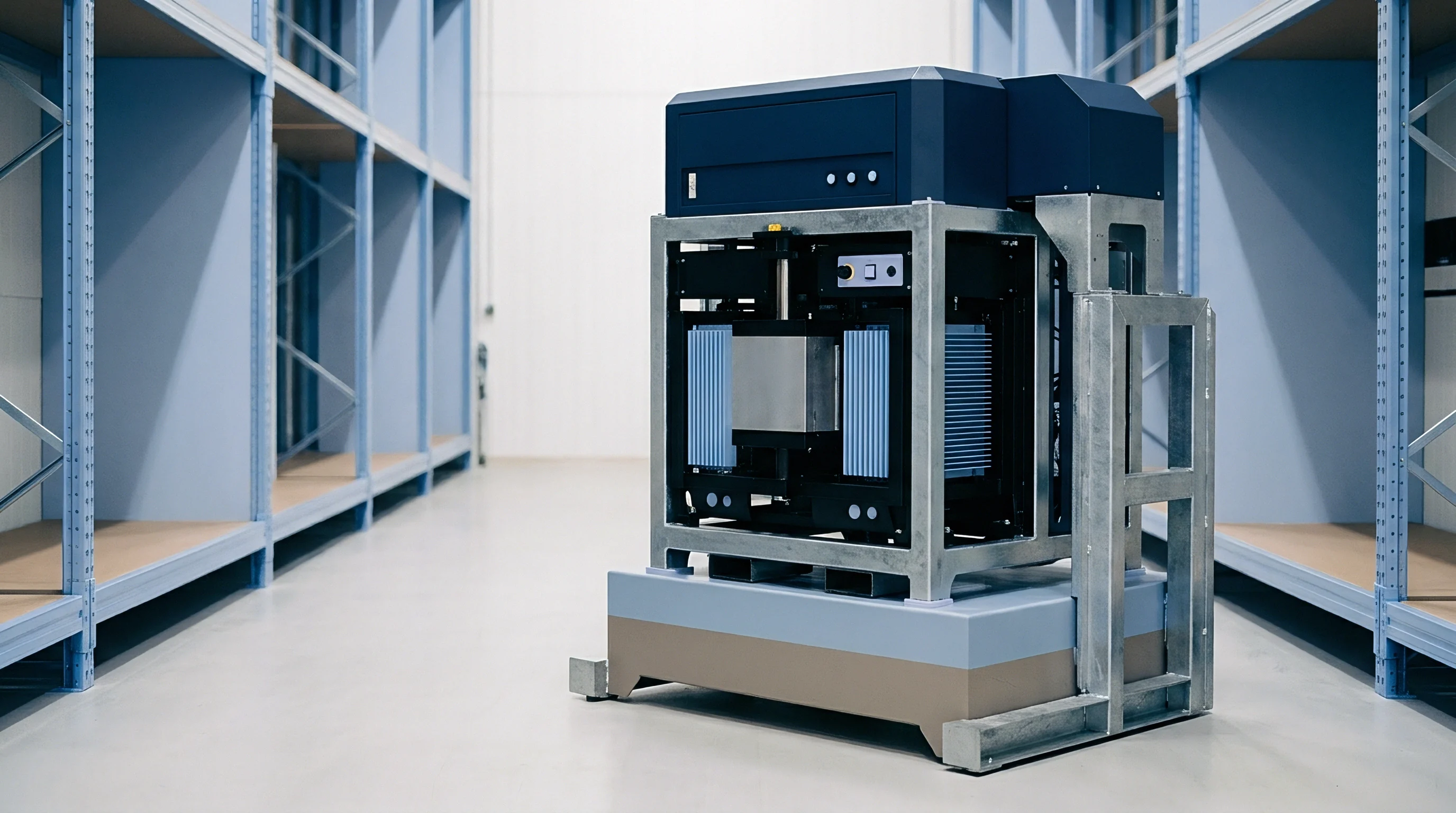
Foil
Pouch cell enclosures rely on multi-layer flexible barrier films to isolate sensitive lithium-intercalation chemistry from ambient atmospheric conditions. Standard laminate architecture uses an outer oriented polyamide layer for mechanical strength, a central aluminum foil core for atmospheric impermeability, and an inner cast polypropylene layer to form the heat seal. Structural integrity depends on maintaining a continuous heat seal around the cell perimeter and current collector tabs.
Any defect in this polymeric barrier opens pathways for trace gas exchange with the external environment, degrading cell performance over long storage and operational periods.
Heat sealing melts adjacent polymer interfaces along the inner cast polypropylene layer using localized heat and pressure to create a cohesive bond. When processing conditions drift outside set thermal and mechanical limits, defects form. Sub-micron voids, micro-wrinkles, and localized thickness variations along the seal line give gases a path around the primary aluminum barrier.
Contamination on the seal flange ~ especially electrolyte splashes or cathode material dust during filling ~ prevents proper polymer fusion, leaving connected capillary channels that run from the internal cavity to the outside air.

Pouch Seal Architecture and Crevice Defect Mechanics
Perimeter seal failures usually start at structural transitions where the geometry shifts from flat film-to-film contact to complex three-phase interfaces. The transition area around the current collector tabs carries heavy mechanical stress. Metallic tab leads ~ typically aluminum for the cathode and nickel-plated copper for the anode ~ need pre-applied polymer sealant films to bridge the surface energy gap between the metal and the polyolefin inner layer.
Microscopic inspection shows that thermal mismatch during sealing pulls micro-voids open at the metal-polymer boundary.
Electrolyte wetting along the internal seal edge speeds up physical degradation when pressure differentials build up. Carbonate solvent mixtures containing ethylene carbonate, dimethyl carbonate, and ethyl methyl carbonate plasticize the cast polypropylene. Extended exposure lowers the polymer’s glass transition temperature, making it creep under mechanical tension.
Small pressure increases inside the pouch, whether from initial formation cycling or warm storage, force open latent crevice channels that stayed tight during dry bench testing.
Seal geometry sets both the length and hydraulic diameter of potential leak paths. Standard perimeter seals run between three and six millimeters wide. Capillary channels formed across a narrow three-millimeter seal have far higher conductance than equivalent defects spanning a six-millimeter seal.
Processing parameters have to balance heat input to prevent squeeze-out, where excessive pressure forces molten polypropylene away from the seal center, thinning the protective barrier and exposing the embedded metal foil to corrosion.

Polyolefin Inner Layer Delamination and Heat Seal Imperfections
Thermal pressure sealing cycles on aluminum laminated film need tight temperature control, within a five-degree Celsius window. Insufficient heat leaves distinct polymer boundary lines intact, resulting in poor inter-diffusion of polypropylene chains across the interface. Too much heat causes severe polymer squeeze-out at the inner seal ridge.
The resulting notch geometry concentrates mechanical stress as the cell swells, triggering adhesive failure between the cast polypropylene layer and the central aluminum barrier.
Interlayer adhesive bonds serve as a second line of defense against gas transport. Polyurethane or modified polyolefin tie-layers laminate the outer polyamide and inner polypropylene layers to the central aluminum foil. Micro-delamination along these adhesive interfaces forms planar gas pathways.
Atmospheric moisture or trace helium enters at the outer cut edge of the laminate, travels along the delaminated interface, and hits any micro-hole in the central foil barrier ~ bypassing the primary heat seal entirely.

Tab Seal Feedthrough Crevices and Polymer Creep
Current collector tab leads pass straight through the perimeter heat seal, creating sharp changes in local geometry. The sudden step in thickness from flat pouch laminate to metallic tab lead forces molten sealant film to flow laterally into the corners around the lead edges. If that polymer flow is incomplete, it leaves triangular crevice defects ~ known in quality control as ear defects ~ right next to the tab edges.
Thermal cycling during cell operation applies cyclic shear stress to the tab sealant interface. Mismatched thermal expansion coefficients between the metallic tab lead and the surrounding polypropylene film produce micro-fissures over long operating periods. Under mechanical vibration, these fissures expand, turning static, isolated voids into active gas transport pathways that destroy long-term hermetic integrity.
Pouch enclosure defect mechanisms exhibit specific structural signatures and physical consequences across the cell perimeter:
- Tab Corner Crevice Voids Triangular microscopic voids formed at the sharp lateral transition between the metallic tab lead and the pouch laminate wall due to insufficient lateral polymer flow during heat sealing.
- Polymer Squeeze Out Channels Localized thinning of the inner cast polypropylene layer caused by excessive sealing pressure, leaving microscopic stress-crack channels across the seal boundary.
- Pinholes in Central Foil Microscopic ruptures within the central aluminum foil layer generated during cold-forming operations for deep pouch cavity shaping, allowing direct gas transport through the barrier core.
- Interlayer Adhesive Delamination Separation of the bonding tie-layer between the inner polyolefin coating and the aluminum foil core, forming planar capillary pathways along the seal flange edge.
- Contamination Inclusion Micro Paths Capillary channels formed around active material dust or electrolyte droplets trapped between polyolefin layers during the perimeter sealing process.
Sub-micron channels in the perimeter seal are hard to catch with basic optical or force-displacement tests. Thermal stress testing combined with differential pressure exposure reveals these latent defects before cells reach the field. Under high vacuum, physical deformation of the envelope wall alters channel cross-sectional areas, shifting measured gas transport rates during testing.
Localized polyolefin thinning along the seal edge is sometimes dismissed as acceptable squeeze-out needed to secure a mechanical bond, while minor crevice voids around tab leads are treated as normal production variance. However, this view ignores how gaseous species migrate through stressed polymers under fluctuating environmental temperatures over time.


Aperture
Gas transport through micro-channels in pouch cell seals shifts between distinct physical flow regimes based on the ratio of the gas mean free path to the characteristic dimension of the leak aperture. This relationship is defined by the Knudsen number ~ the gas mean free path divided by the channel hydraulic diameter. Converting measured helium leak values into equivalent air or moisture transport rates under field operating conditions requires identifying which flow regime governs the leak.
Continuum flow occurs at low Knudsen numbers, typically below 0.01, where collisions between molecules dominate gas behavior. Here, gas movement follows viscous flow mechanics modeled by the Poiseuille equation. Laminar viscous flow rate scales inversely with dynamic viscosity and directly with the square of the pressure differential across the leak path.
As channel dimensions shrink or differential pressure drops, the mean free path approaches the channel diameter, triggering a transitional flow state.
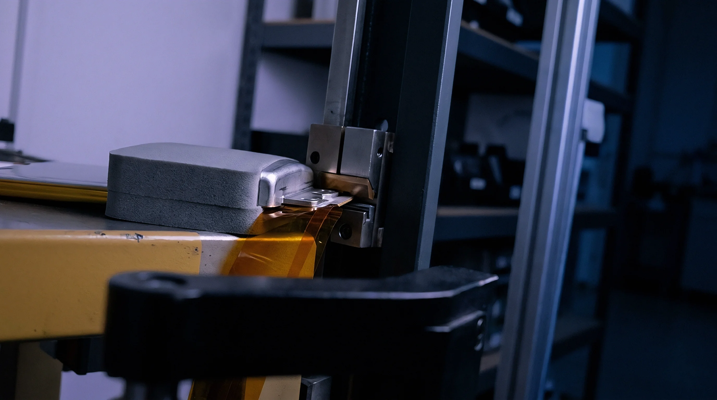
Gas Molecular Dynamics in Microscopic Leak Channels
Molecular flow dominates gas transport when the Knudsen number exceeds 1.0, which corresponds to micro-channel diameters below 0.1 micrometers under standard atmospheric pressure. In molecular flow, gas molecules strike the internal channel walls far more often than each other. Transport rates in this regime depend entirely on molecular thermal velocity and channel geometry, completely independent of gas dynamic viscosity.
Converting helium leak rates to standard equivalent air leak rates depends directly on the active flow regime. In molecular flow, the transport rate of a gas species scales inversely with the square root of its molar mass. With helium having a molar mass of 4.002 grams per mole compared to air’s average of 28.97 grams per mole, molecular helium passes through a given micro-aperture roughly 2.69 times faster than air under identical temperature and pressure conditions.
A measured helium leak rate of 1e-7 mbar L/s under hard vacuum translates to an equivalent air leak rate of 3.72e-8 mbar L/s within the molecular flow regime at 23 degrees Celsius.
Viscous continuum flow requires a different conversion approach, as volumetric flow scales inversely with dynamic viscosity. At room temperature, helium has a dynamic viscosity of 19.6 micropascal-seconds compared to air’s 18.2 micropascal-seconds, meaning helium actually flows slightly slower than air under purely viscous conditions for a given pressure gradient. Accurate leak rate quantification depends on establishing whether the physical aperture operates in the molecular, transitional, or viscous regime.

Knudsen Flow Transitions and Isothermal Gas Transport Formulas
Transitional flow takes place across Knudsen numbers between 0.01 and 1.0, where viscous momentum transfer and wall molecular scattering happen at the same time. Engineering models use the Knudsen equation to bridge continuum Poiseuille flow and molecular flow calculations, modeling total gas transport as the sum of a viscous flow term and a molecular Knudsen slip term.
Pressure across the pouch cell envelope alters the active flow regime during testing. Subjecting a cell to hard vacuum mass spectrometry creates a steep pressure differential that increases the mean free path inside the leak aperture. This pressure drop can push a marginal defect from viscous continuum behavior into pure molecular flow during the test, altering the measured helium flow rate relative to ambient storage conditions.
| Gas Species | Molar Mass (g/mol) | Molecular Diameter (nm) | Dynamic Viscosity (μPa·s) | Mean Free Path at 1 atm (nm) | Molecular Flow Ratio vs Air |
|---|---|---|---|---|---|
| Helium (He) | 4.002 | 0.260 | 19.60 | 192.5 | 2.69 |
| Air (Average) | 28.970 | 0.370 | 18.20 | 67.0 | 1.00 |
| Nitrogen (N2) | 28.013 | 0.375 | 17.80 | 65.4 | 1.02 |
| Oxygen (O2) | 31.999 | 0.360 | 20.40 | 69.3 | 0.95 |
| Water Vapor (H2O) | 18.015 | 0.320 | 10.10 | 41.2 | 1.27 |
| Carbon Dioxide (CO2) | 44.010 | 0.330 | 14.80 | 43.7 | 0.81 |
Gas flow calculations through micro-cavities establish clear bounds for quality control thresholds. Standard Equivalent Air Leak Rate represents the nominal air flow passing through a leak channel when upstream pressure is 1.0 atmosphere and downstream pressure is absolute zero vacuum at 293 Kelvin. Converting measured test values back to standard equivalent air conditions eliminates ambient temperature and pressure variability from factory quality metrics.
Molecular transport modeling shows that apertures smaller than 0.5 micrometers in diameter operate mostly in the molecular flow regime under standard laboratory vacuum test conditions. Pressure gradients applied during quality control verification shift gas dynamics along predictable physical curves.
Determining equivalent moisture ingress from tracer gas measurements requires applying the ratio of molecular masses under molecular flow assumptions. Water vapor transport through sub-micron channels follows Knudsen molecular kinetics when absolute pressure remains low.
A leak channel operating purely in the molecular regime passes tracer gas species strictly according to their inverse molecular weights, regardless of internal channel surface roughness. Non-condensable trace gases set the physical ceiling for channel throughput under identical pressure gradients.


Enclosure
Testing fully sealed pouch cells for micro-leaks requires containment systems that isolate trace gas emissions from ambient contamination. Vacuum mass spectrometry is the primary high-sensitivity test used in commercial battery manufacturing. Enclosing a cell inside a rigid vacuum chamber allows high-performance pumps to pull baseline pressure down so ion detectors can register minute helium leakage emerging from perimeter heat seals.
Two main helium testing configurations are used for pouch cell quality assurance: direct trace gas pre-dosing prior to final sealing, and post-seal helium pressure bombing. Pre-dosing injects a known volumetric fraction of helium into the pouch cavity alongside the liquid electrolyte during final vacuum sealing. The sealed cell retains an internal helium concentration, typically between 5% and 20% by volume, creating an immediate internal partial pressure that drives helium through perimeter defects into the test chamber.

Vacuum Mass Spectrometry and Trace Gas Dosing Mechanics
Post-seal bombing subjects finished cells to high-pressure helium inside an external pressure vessel. Helium penetrates through micro-leaks into the internal free volume over a set exposure period. After pressurization, the cell undergoes a short atmospheric flush to clear surface-absorbed helium before moving to the vacuum mass spectrometer test chamber.
Chamber pump-down draws trapped helium back out through defect channels, where the spectrometer ion source detects the mass-to-charge ratio of helium ions.
Direct pre-dosing provides better measurement accuracy than bombing because internal tracer gas concentration is known precisely from injection. Bombing efficiency depends on internal free volume, bomb pressure, soak duration, and dwelling time in room air before testing. If helium fails to penetrate tightly packed electrode stacks during bombing, physical defect sizes are easily underestimated.
During hard vacuum testing of pouch envelopes, residual moisture on unwashed tab surfaces can produce a 0.4 mbar baseline offset. Chamber pump-down cycles have to include regulated heating or dry gas purging to desorb moisture from exposed polyolefin film surfaces. Outgassing of organic solvents or surface contaminants raises chamber pressure and degrades background detection limits.
Chamber base pressure must reach 1e-4 mbar prior to signal acquisition to achieve a background helium noise floor below 1e-10 mbar L/s.
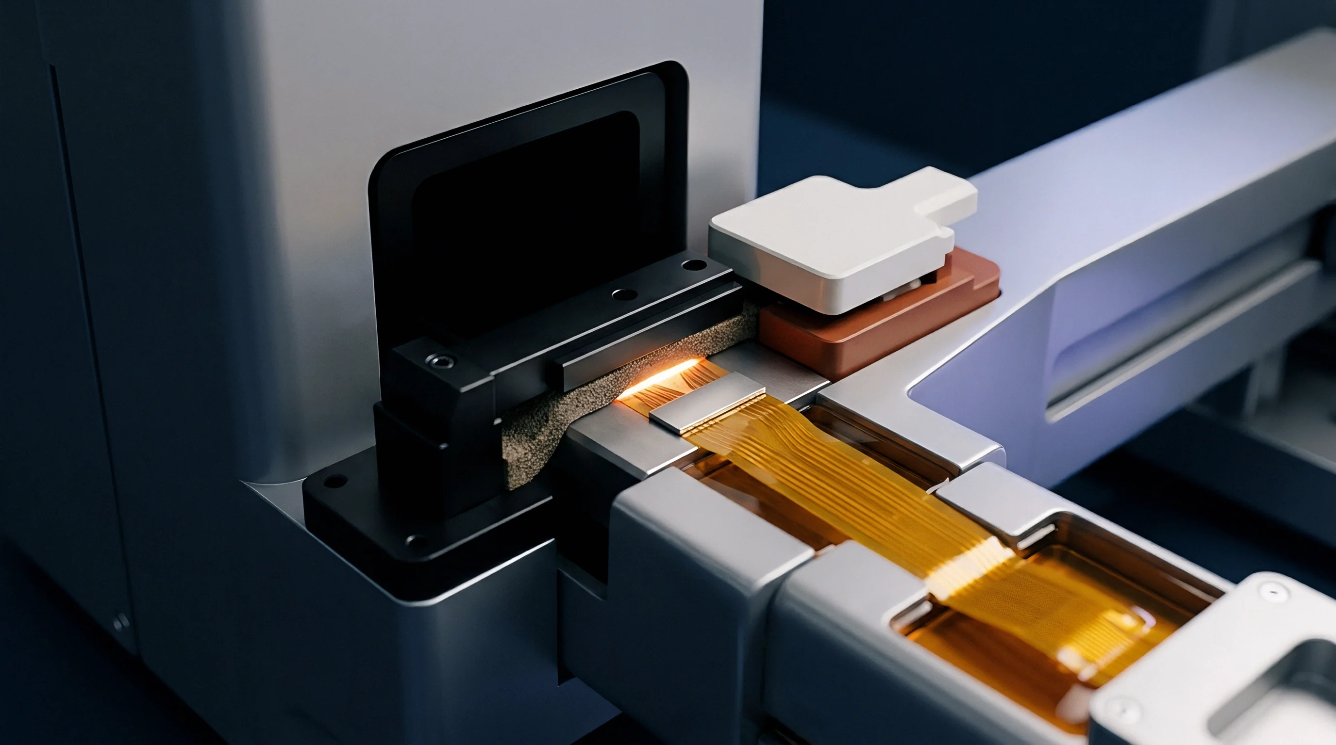
Helium Bombing Dynamics for Sealed Commercial Cells
Bombing methodology relies on precise mathematical modeling to calculate internal helium partial pressure before chamber evacuation. Internal void volume varies with stack packing density, electrolyte fill ratio, and gas pouch trimming margins. Cells with low internal free volume saturate quickly with helium during bombing, but they also lose trapped tracer gas just as fast during transfer to the vacuum chamber.
Transfer time between the helium bombing vessel and the vacuum test chamber is a critical variable. Long transfer delays let internal helium escape through larger leaks before measurement starts, resulting in false passes. Quality control protocols enforce a tight transfer window, typically under two minutes, to preserve detection sensitivity for larger micro-defects.
Testing execution proceeds through a strict mechanical and vacuum sequencing routine to ensure precise measurements:
- Load the sealed pouch cell into the stainless steel test fixture with integrated mechanical support plates to restrict pouch wall expansion under vacuum.
- Seal the test chamber enclosure and initiate primary roughing pump evacuation down to a crossover pressure of 1.0 mbar.
- Engage the high-vacuum turbomolecular pump to draw chamber enclosure pressure down below 1e-4 mbar.
- Isolate the primary chamber pump line and route exhaust gas to the helium mass spectrometer ion source.
- Sample the mass-to-charge ratio four signal for a duration of ten seconds to establish peak helium transport rates.
- Vent the chamber enclosure with high-purity dry nitrogen gas to sweep residual tracer gas and prevent background accumulation.
- Unload the cell and verify signal decay back to background noise floor before loading the subsequent test specimen.
Vacuum levels shift baselines. Pouch envelope expansion under vacuum forces internal cell gas toward perimeter seal margins. Restraining fixtures with planar aluminum contact plates must maintain uniform surface clamping pressure across the active electrochemical area.
Unrestrained pouches expand under hard vacuum, risking mechanical seam failure or artificial seal distortion during measurement.
Fine leak measurements require active background suppression systems. Residual helium in atmospheric air, present at roughly 5.2 parts per million by volume, continuously penetrates vacuum chamber elastomeric seals. Quadrupole mass spectrometers rely on secondary electron multipliers to isolate true leak signals from background drift.
Accumulation testing offers an alternative for lower-cost line verification where high-vacuum systems are impractical. The pouch cell sits inside a sealed atmospheric chamber purged with clean, helium-free carrier gas. Helium leaking from the cell accumulates over a fixed dwell time, and a sensor tracks the concentration rise.
Accumulation systems offer lower sensitivity than hard vacuum setups, making them suitable primarily for gross leak detection.
Process validation requires setting explicit upper bounds on permissible background helium signals inside the test chamber. High-throughput production lines running continuous helium testing face ambient background accumulation from minor system vents. If an uncalibrated accumulation chamber permits baseline helium levels to drift high enough, it triggers false lot rejections across production shifts, halting operations.

Gauge
Accurate quantification of helium leak rates relies on calibration regimes tied directly to traceable primary leak standards. Mass spectrometer response factors vary non-linearly with ionizer filament age, background chamber pressure, and ambient temperature fluctuations. Calibrated reference leaks with known gas loss rates provide the baseline needed to convert measured ion detector currents into absolute mass flow units.
Primary calibration standards use either capillary tubes or permeable quartz glass membranes to deliver stable, known helium flow rates. Capillary standards feed helium from a small reservoir through a narrow physical channel, keeping the temperature coefficient low at approximately 0.2% per degree Celsius. Quartz permeation standards rely on atomic diffusion through a heated glass disk, which exhibits higher temperature dependency, typically 3% to 4% per degree Celsius.

Calibration Standards and Background Helium Signal Isolation
Calibration procedures mandate daily baseline verification using external standard leaks attached directly to the vacuum test chamber manifold. Mounting reference leaks close to the test specimen ensures identical gas conductance paths through the vacuum manifold to the ion source. Dynamic tuning adjusts electrometer amplifier gain to align output readings with the certified reference value on the standard leak’s calibration tag.
Isolating the leak signal requires real-time subtraction of ambient background noise from raw measurement profiles. Mass spectrometer software records the residual helium signal immediately before opening the sample chamber isolation valve. Subtracting this background offset from the peak signal recorded during evaluation isolates the true volumetric flux coming from pouch envelope defects.
Capillary calibrated leaks are preferred over quartz diffusion standards when calibrating line detectors for fast thermal response. Capillary units maintain constant flow across factory room temperature variations without requiring integrated electronic heater jackets. Frequent re-certification against national metrology institute references maintains traceability during quality audits.

Where Does High Vacuum Bombing Induce Seal Delamination?
Placing pouch cells inside hard vacuum chambers creates a severe pressure differential across the flexible polyolefin heat seal. Pouch envelopes lack the rigid walls of cylindrical or prismatic metal cans. Internal gas expands against the inner polypropylene film, concentrating peel stresses directly at the seal squeeze ridge.
High vacuum bombing followed by rapid evacuation produces mechanical stress spikes that can cause latent seal wrinkles to delaminate into open leak channels.
Restraining fixtures with mechanical boundary plates reduce structural seal damage during vacuum evacuation. Plate gap tolerances must match nominal cell thickness within 0.1 millimeters. Excessive clearance lets the pouch expand and induces peel stresses along tab seal feedthroughs, while excessive clamping force crushes electrode stack edges and risks internal short circuits.
| Pouch Envelope Format | Internal Free Volume (cm³) | Bomb Pressure (bar absolute) | Bomb Dwell Time (hours) | Transfer Dwell Limit (min) | Minimum Detectable SEALR (mbar·L/s) |
|---|---|---|---|---|---|
| Consumer Electronics (5 Ah) | 1.2 | 4.0 | 2.0 | 1.5 | 2.0e-7 |
| Automotive Traction (60 Ah) | 8.5 | 3.0 | 6.0 | 2.0 | 5.0e-8 |
| Energy Storage (100 Ah) | 15.0 | 2.5 | 12.0 | 3.0 | 1.0e-8 |
| Ultra-Thin Pouch (2 Ah) | 0.4 | 5.0 | 1.0 | 1.0 | 5.0e-7 |
| High-Capacity Long Pouch (120 Ah) | 22.0 | 2.0 | 16.0 | 3.0 | 8.0e-9 |
Signal attenuation during testing occurs when internal trace gas concentration drops rapidly during vacuum exposure. Small cells with low free volume exhaust their internal helium supply within seconds in hard vacuum. Calibration procedures must account for tracer gas depletion kinetics during long measurement dwell times.
Temperature variations across the test chamber alter gas permeation rates through polyolefin edge seals. Polypropylene permeability to helium increases exponentially with temperature following an Arrhenius relationship. Operational quality procedures mandate holding cell temperature within a narrow two-degree Celsius window so thermal permeation does not mask physical crevice defects.
DIN EN ISO 20485 Clause 7.3 mandates that system calibration must be re-verified whenever ambient room temperature drifts by more than three Kelvin during continuous testing.
Sensor drift in quadrupole mass spectrometers comes from ion source contamination and electrometer aging. Electrolyte solvent vapor escaping through gross leaks deposits organic residue onto tungsten ionizer filaments, reducing ion emission efficiency. Automated diagnostics monitor filament emission current and electron multiplier voltage levels, triggering cleaning cycles when calibration scaling factors drift beyond 15 percent of initial setup baselines.
Primary calibration files must document physical standard serial numbers, certified leak values, working gas compositions, and environmental correction factors. Dynamic signal processing algorithms apply polynomial drift compensation curves between manual recalibration intervals. System verification logs remain mandatory records for production batch certification.
International Standard ISO 17025 Section 7.8 requires test reports to include an explicit statement of measurement uncertainty calculated across calibration chains, ambient environmental variations, and sensor non-linearity margins.


Moisture
Translating measured helium leak rates into long-term battery degradation kinetics requires modeling water ingress and electrolyte loss over multi-year service lives. Atmospheric moisture entering a pouch cell reacts aggressively with lithium hexafluorophosphate (LiPF6) dissolved in carbonate solvents. Hydrolysis generates hydrofluoric acid (HF) alongside secondary gaseous products, degrading electrochemical performance across both electrodes.
Hydrofluoric acid generation starts a destructive cascade inside the cell. Acidic species attack the protective Solid Electrolyte Interphase (SEI) layer on the graphite anode, dissolving lithium fluoride and carbonate compounds. Continuous re-passivation consumes active lithium ions from the cathode, driving irreversible capacity loss.
Hydrofluoric acid also attacks the transition metal oxide cathode structure, leaching manganese, nickel, or cobalt into the liquid electrolyte.
Water Ingress Kinetics and Hydrofluoric Acid Degradation
Dissolved transition metal cations migrate across the porous separator and deposit onto the graphite anode surface. These metallic deposits act as catalytic sites for continuous parasitic electrolyte decomposition, accelerating self-discharge and impedance growth. Ingress rates as low as 10 micrograms of water per year cause measurable capacity fade in high-nickel chemistries such as NMC-811.
Atmospheric moisture ingress kinetics depend on ambient relative humidity, external storage temperature, and seal leak geometry. A helium leak rate of 10-6 mbar·L/s corresponds to a water vapor mass flux of approximately 0.15 milligrams per year under standard atmospheric conditions at 50% relative humidity. Setting maximum allowable leak limits requires quantifying the chemical water tolerance of specific cathode and anode chemistries over target operating lifetimes.
A cumulative moisture ingress of 50 ppm relative to total electrolyte mass reduces standard NMC-811 pouch cell 80 percent capacity retention retention life by approximately 35 percent.
Electrolyte loss is the reverse failure mode driven by seal micro-leaks. Low-boiling-point carbonate solvents like dimethyl carbonate and ethyl methyl carbonate evaporate through perimeter seal channels into the surrounding air. This solvent loss increases electrolyte viscosity and reduces ionic conductivity, resulting in elevated internal ohmic resistance and rapid power fade, especially at low operating temperatures.

Electrolyte Solvent Vapor Loss and Internal Cell Swelling
Evaporation of volatile solvents leaves behind higher concentrations of cyclic carbonates and dissolved salts, altering electrolyte fluid properties. As solvent volume drops, the porous separator dries out near the top margins of the electrode stack. Dry separator regions stop participating in electrochemical reactions, causing non-uniform current density across active electrode surfaces that accelerates localized lithium plating during fast charging.
Gaseous degradation products from hydrofluoric acid reactions cause progressive internal cell swelling. Pouch expansion pushes active electrode surfaces out of planar contact, increasing local charge transfer resistance. Severe pouch swelling can even rupture adjacent cells inside tightly constrained module enclosures.
Quality control teams apply standardized decision frameworks to establish pass/fail helium leak rate thresholds tailored to specific application requirements and warranty targets:
- Chemically Sensitive High Nickel Chemistries Mandate a maximum helium leak threshold of 1e-7 mbar L/s to restrict total water ingress below 15 micrograms per year over a 10-year service life.
- Standard LFP Commercial Chemistries Permit a higher upper leak limit of 1e-6 mbar L/s due to superior chemical stability of the iron phosphate cathode frame against hydrofluoric acid attack.
- High Power Thin Envelope Formats Enforce a strict leak limit of 5e-8 mbar L/s to prevent volatile solvent evaporation from drying out low-volume separator layers.
- Grid Storage Heavy Formats Require a helium leak limit of 2e-7 mbar L/s to ensure continuous hermetic isolation across 15-year to 20-year target warranty operational windows.
Calculating equivalent service life degradation requires matching Knudsen transport models with electrochemical decay equations. Water ingress drives active mass loss through parasitic lithium consumption. Fast transport channels exacerbate performance degradation.
| Cathode Chemistry Format | Electrolyte Water Limit (ppm) | Max Allowable SEALR (mbar·L/s) | 10-Year Water Ingress (mg) | Predicted Capacity Loss (%) | Predicted DCIR Rise (%) |
|---|---|---|---|---|---|
| NMC-811 / Graphite | 20 | 1.0e-7 | 0.15 | 18.5 | 42.0 |
| NMC-622 / Graphite | 50 | 3.0e-7 | 0.45 | 12.0 | 25.0 |
| LFP / Graphite | 100 | 1.0e-6 | 1.50 | 6.5 | 14.0 |
| LTO / NMC-532 | 30 | 2.0e-7 | 0.30 | 8.0 | 18.0 |
| Silicon-Carbon / NMC-811 | 15 | 5.0e-8 | 0.08 | 24.0 | 58.0 |
Electrochemical life models confirm that high-nickel pouch cells operating under tropical ambient storage conditions require leak verification systems capable of resolving helium signals down to 10-7 mbar·L/s. Micro-leak quantification forms the baseline defense against premature thermal and electrochemical field returns.
Long-term field reliability models depend directly on the accurate conversion of short-term helium test data into multi-year atmospheric water mass transport rates.
Unresolved questions remain regarding the precise diffusion coefficient of water vapor through plasticized polypropylene seals relative to physical micro-capillary channel transport under real-world thermal cycling stress conditions.


Acceptance
Integrating helium micro-leak detection into commercial pouch cell manufacturing lines requires balancing inspection throughput against high-sensitivity vacuum requirements. Production lines running above 30 cells per minute demand multi-chamber automated leak testing stations with parallel vacuum manifolds. High-speed quality control systems execute automated cell loading, pneumatic tool clamping, fast vacuum evacuation, helium sampling, and nitrogen purging in cycle times under ten seconds.
Pneumatic clamping fixtures inside automated vacuum chambers perform two functions: sealing the chamber perimeter and restraining the flexible pouch envelope during pressure drop. Aluminum support plates contact the planar cell faces, maintaining uniform contact pressure between 0.02 and 0.05 MPa. Clamping restrains internal gas expansion while preventing local strain along perimeter heat seals that could generate false leak indications during measurement cycles.
Inline Quality Assurance and Clamping Fixture Mechanics
Automated inline testing enforces zero-tolerance pass/fail screening based on pre-programmed helium leak current thresholds. Cells registering helium signals above the cutoff trigger automated rejection gates, routing defective units to quarantine bins for off-line failure analysis. Rejection threshold parameters stay locked under supervisor administrative controls to prevent manual overrides on the shop floor.
Incoming inspection procedures at battery pack assembly facilities use statistical sampling plans to verify received lot quality. Standard quality control protocols apply ISO 2859-1 or ANSI/ASQ Z1.4 Normal Inspection Level II, setting Acceptable Quality Level (AQL) limits for critical hermetic defects. Critical defect classification enforces zero-defect criteria (AQL = 0.01), requiring immediate lot rejection and supplier quarantine if even a single leaky cell turns up in a sample batch.

Lot Conformity Protocols and Transport Certification Alignment
Helium leak testing provides key supporting evidence for dangerous goods transport compliance files. UN 38.3 Recommendation T.3 (Altitude Simulation) subjects commercial lithium cells to low environmental pressure of 11.6 kPa for at least six hours at 20 degrees Celsius. Cells with defective perimeter seals leak solvent or swell under reduced pressure, failing UN 38.3 safety qualification and blocking legal air and ocean freight transport.
International Standard IEC 62133-2 Clause 7.2.1 mandates that secondary sealed cells show no liquid electrolyte leakage under thermal storage and mechanical shock testing. Validated helium leak testing records showing baseline leak rates below 10-6 mbar·L/s serve as technical justification in safety dossiers proving long-term compliance with IEC liquid retention requirements.
Supplier quality agreements specify exact testing parameters, chamber vacuum levels, helium pre-dosing percentages, and calibration frequencies required across manufacturing plants. Procurement contracts incorporate explicit financial liability clauses transferring recall costs back to the cell manufacturer if field failures trace back to lot non-conformities caused by seal defects that passed factory quality gates.
Writing rejection thresholds directly into quality agreements avoids relying on general lot acceptance criteria. Standardized supply contracts mandate that cell manufacturers provide certified batch helium testing logs alongside UN 38.3 Test Summaries prior to shipping international freight containers.
Commercial purchase agreements mandate that cell suppliers maintain full traceability linking individual cell serial numbers to corresponding inline helium test records, chamber vacuum pump-down curves, and calibration timestamps for a minimum retaining window of ten years.