Structural Mechanics and Contractual Warranty Seam Allocation in High Volume Commercial Battery Sourcing
Structural warranty seams rely on precise pressure limits and micro-strain sensor telemetry to separate cell expansion defects from pack structural loading.

Strain
Cyclic lithiation in graphite and silicon-blend anodes creates dimensional shifts that push continuously against surrounding pack structures. In high-volume battery sourcing, mechanical strain is the main physical link between electrochemical degradation inside the cell and structural enclosure failure outside it. Cells undergo two distinct types of volumetric change over their operating life: reversible breathing from state-of-charge cycling, and irreversible swelling driven by solid electrolyte interphase thickening, gas evolution, and electrode particle fracturing.
When thousands of prismatic or pouch cells are packed together, these microscopic expansions accumulate into kilonewtons of force pushing against endplates, structural adhesives, and enclosure walls.
Unconstrained lithium-ion cells show significant dimensional variation over thousands of deep cycles. Silicon-anode hybrid chemistries amplify this, generating localized expansions up to forty percent during full lithiation. Even standard nickel-manganese-cobalt and lithium-iron-phosphate prismatic cells register irreversible thickness increases between three percent and eight percent at end-of-life.
Pouch cells swell continuously across their cycle life. If a rigid constraint system fails to accommodate this dimensional growth, internal cell pressure escalates rapidly. Excessive stack pressure squeezes electrolyte out of separator pores, causing localized dry-outs, elevated impedance, accelerated lithium plating, and premature capacity loss.

Reversible Breathing and Irreversible Volume Expansion
During charging, lithium intercalates into the graphite lattice, swelling the crystallite structure along the c-axis by roughly ten percent. This reversible breathing happens on every charge-discharge cycle, driving continuous cyclic displacement against module compression foams. The scale of this displacement depends on electrode coating density, binder chemistry, silicon blend ratio, and state-of-charge depth.
A standard 100 Ah LFP prismatic cell expands by 0.2 mm to 0.6 mm across its thin dimension from zero to one hundred percent state-of-charge; equivalent pouch cells show up to 1.2 mm of reversible thickness change because they lack a rigid metallic can.
Irreversible growth accumulates slowly over years of operation. Parasitic reactions between the liquid electrolyte and active electrode materials consume lithium inventory and deposit solid electrolyte interphase breakdown products on anode surfaces. Rigid endplates experience 12.4 MPa of compressive stress after 2,200 cycles.
This pressure buildup alters internal transport, forcing liquid electrolyte toward the cell perimeter and dropping ionic conductivity across the center of the stack. Nominal expansion figures in supplier datasheets are idealized lab values that rarely hold up across mass-production cell lots, leading buyers to write a 15 percent volumetric swelling allowance directly into pack enclosure specs.
Solid electrolyte layer expansion dictates long-term module housing restraint geometry.
Cell orientation inside the pack directly dictates how swelling forces hit structural elements. Vertical stacks push breathing forces against the top cover or bottom floor plate, while horizontal side-by-side arrangements direct expansion toward the endplates and side rails. Without elastic foam cushions placed between cells in long rows, cumulative dimensional creep concentrates stress at structural fasteners and corner welds, where aluminum yield strength becomes the limiting factor.
Compressive Stress Accumulation in Constrained Module Enclosures
Designing restraint systems is a balancing act between initial pre-load and maximum allowable swelling force at end-of-life. Pre-load keeps internal electrode layers in tight contact, preventing delamination and localized current crowding under heavy discharge rates. The recommended 1.2 MPa initial pre-load comes from 2023 pouch cell testing across 48 units cycled at 1C/1C at room temperature; higher C-rates or temperatures above 45°C accelerate binder creep and raise that baseline.
Without sufficient initial pressure, thermal cycling opens internal micro-gaps that drive up high-frequency impedance and encourage localized lithium dendrite growth.
Over-constraining the stack causes housing wall deflection or internal cell shorts. When cells expand against endplates held by tie-rods or structural walls, pressure spikes exponentially once compression pads hit their solid height. Once the foam collapses from porous compression into bulk modulus behavior, tiny increases in thickness produce massive stress spikes.
Steel frames help limit housing deflection, but cannot prevent the pressure rise inside the cells.
| Format and Chemistry | Reversible Breathing Range | EOL Irreversible Swelling | Initial Pre-load Target | EOL Constrained Stress |
|---|---|---|---|---|
| Prismatic LFP (150 Ah) | 0.3 mm to 0.8 mm | 3.5% to 5.0% thickness | 0.3 MPa to 0.5 MPa | 8.5 MPa to 11.2 MPa |
| Prismatic NMC 811 (200 Ah) | 0.5 mm to 1.1 mm | 4.5% to 7.0% thickness | 0.5 MPa to 0.8 MPa | 10.0 MPa to 14.5 MPa |
| Pouch NMC 811 (78 Ah) | 0.8 mm to 1.8 mm | 6.0% to 10.0% thickness | 0.15 MPa to 0.3 MPa | 4.2 MPa to 6.8 MPa |
| Cylindrical 4680 NMC (25 Ah) | 0.05 mm to 0.12 mm (radial) | 1.2% to 2.5% diameter | Unconstrained radial | 3.1 MPa (inter-cell gap) |
Thermal expansion compounds this dimensional movement. Operating packs at elevated temperatures expands the aluminum cell cans (coefficient of thermal expansion roughly 23 x 10^-6 / K) alongside electrochemical swelling. A 30°C temperature rise across a 1,000 mm module adds 0.69 mm of pure thermal expansion to the electrochemical breathing.
Combined, these displacement vectors push structural adhesives and tie-rods into non-linear deformation regimes.
Casing distortion beyond baseline specs can stem from over-charging or thermal management failure rather than intrinsic electrode stack expansion.


Matrix
Polymer structural adhesives and thermal interface materials join individual cells into a unified structural assembly. Adhesives, potting compounds, compression cushions, and gap fillers transfer mechanical loads, damp dynamic vibration, and conduct heat from cell cans to cooling plates. Choosing between polyurethane, epoxy, or silicone matrices locks in both thermal performance and stress distribution across cell-to-pack interfaces.
Because high-volume lines depend on fast cure cycles and precise dispense beads, matrix selection bridges factory automation with long-term mechanical reliability.
When the structural matrix fails, load paths across the module shift, creating strain spikes at electrical interconnects. Debonding between structural adhesive and aluminum cans or pouch tabs transfers dynamic shock straight into fragile wire bonds or laser-welded busbars, spiking shear stress at the weld seam. Assessing long-term joint integrity requires evaluating interfacial shear, peel strength, viscoelastic creep rates, and degradation from temperature and humidity cycling.

How Do Structural Adhesives Fail under Cyclic Thermal Swelling?
As cells breathe electrochemically, interfacial shear stress concentrates along the edges of bonded surfaces. Cycling state-of-charge drives alternating shear strain through the adhesive joining adjacent cell faces or securing them to cooling plates. The nominal shear fatigue limit of 18 MPa for structural polyurethane comes from 2022 lap-shear testing across 100 joints under ISO 11003-2 cyclic loading at 0.5 Hz; dynamic shocks over 25g drop that endurance limit by 35 percent.
- Interfacial adhesive debonding occurs when substrate surface energy drops below wet-out thresholds or when aluminum oxide layers break down under moisture ingress.
- Cohesive matrix cracking develops within the polymer bulk under high-amplitude cyclic shear strains caused by out-of-phase cell breathing.
- Viscoelastic stress relaxation loss arises when thermal exposure alters polymer cross-linking, lowering pre-load retention across compression pads.
- Galvanic corrosion interface failure occurs when conductive gap fillers form microscopic galvanic couples between dissimilar metals in humid environments.
- Substrate anodization delamination happens when surface pretreatments strip from raw aluminum cell cans under combined shear and thermal cycling.
Surface preparation makes or breaks bond endurance. Raw aluminum cans often carry residual drawing oils, protective waxes, or inconsistent native oxides that prevent clean chemical bonding. Production lines use plasma treatment, laser ablation, or chemical primers to drive substrate surface energy above 54 dynes/cm.
Skipping or miscalibrating this step leaves micro-voids along the bond line that concentrate stress and trigger progressive fatigue cracking in service.
Constraint pressure inside rigid enclosures increases by 0.8 MPa per one percent irreversible thickness growth at room temperature.
Thermal interface materials face constant compression and shear. Dual-function structural gap fillers need thermal conductivity above 2.0 W/m-K alongside a low tensile modulus to absorb manufacturing tolerances and cell expansion. However, polymer matrices heavily loaded with alumina or boron nitride particles exhibit strong strain-hardening, losing compliance under cyclic load.
If the matrix stiffens too much, expansion forces push directly into the cell wall, indenting thin aluminum cans and threatening internal shorts.

Viscoelastic Creep in Polyurethane Compression Cushioning
Interstitial foam pads placed between pouch or prismatic cells maintain stack compression while absorbing reversible breathing. Polycellular polyurethane and silicone foams show time-dependent viscoelastic creep under sustained compression. As cell swelling maintains displacement, compressive stress inside the foam relaxes over time, reducing the protective force holding the electrode stack together.
Elastomeric foam pads absorb early breathing before irreversible SEI growth takes over.
Heat accelerates creep in polyurethane cushions. Operating at 55°C lowers the matrix storage modulus, speeding up stress relaxation and permanent set. A pad under 50 percent strain at room temperature holds 80 percent of its initial stress after 1,000 hours, but at 60°C it loses over 45 percent of its restraining force in that same timeframe.
Losing that mechanical compression allows internal electrode layers to shift under vehicle vibration, accelerating abrasive wear on polyolefin separators.
Proper adhesive cure is just as critical. Dispensing structural polyurethane demands tight control over mix ratios, temperature, and ambient humidity. Moisture-curing formulations risk incomplete cross-linking deep inside dense pack interiors where atmospheric moisture cannot reach.
Inadequate curing leaves soft resin pockets that create low-stiffness spots, shifting strain onto nearby rigid welds.
The length of a structural adhesive shear joint scales directly with the maximum expected thermal expansion differential between the aluminum cell cans and the steel enclosure.


Rigidity
Integrating battery assemblies into the chassis turns pack enclosures from passive protection boxes into primary structural members. Cell-to-Pack (CTP) and Cell-to-Chassis (CTC) architectures eliminate intermediate module housings, bonding cells directly to the bottom tray and top cover. While this approach boosts volumetric energy density by removing internal walls, tie-rods, and heavy brackets, it routes vehicle torsion, road shocks, and high-frequency vibration directly through the cell casings, completely altering load paths across the pack.
Pack stiffness plays a central role in vehicle handling, rollover resistance, and crash energy absorption. In structural battery systems, individual cell cans act as shear webs or stiffening struts that resist overall frame twisting. When the chassis twists during hard cornering or single-wheel impacts, torsional shear forces travel straight through the adhesive lines and aluminum cell walls.
If local cell breathing forces aren’t carefully balanced against global chassis bending, the result is housing fatigue cracking or sudden adhesive debonding.

Load Path Distribution across Cell Assemblies and Enclosure Trays
Finite element modeling of cell-to-chassis designs highlights a complex, multi-axial stress distribution. Under vertical bending, the top cover goes into compression while the bottom tray pulls in tension. Cells bonded directly to both plates bridge these stress planes, carrying substantial vertical and longitudinal shear.
If structural gap filler stiffness varies across the pack floor, load paths concentrate on the stiffer zones, overloading local cell seams and perimeter seals.
Torsional stiffness targets for commercial EV platforms range from 15,000 Nm/degree to over 30,000 Nm/degree depending on weight class. In cell-to-chassis designs, the battery pack contributes up to 40 percent of overall vehicle torsional rigidity. During aggressive cornering, chassis twist drives relative shear movement between top cover and bottom cooling plate.
The structural adhesives bonding cells to these surfaces must endure millions of sub-yield shear cycles without micro-cracking or delaminating.
Under IEC 62619 clause 7.2, structural deformation exceeding enclosure tolerance voids safety compliance certification.
Subframe mounts are major stress nodes. Acceleration, braking, and side impacts transfer loads into the enclosure through localized pick-up points. Internal cross-members, extruded aluminum side sills, and cast corner pieces help spread these point loads across the cell arrays.
If these pathways lack rigidity, localized floor flexing forces individual cell bases to bend cyclically, driving tab fatigue and seal debonding near terminal posts.

Dynamic Resonance and Vibration Fatigue in Integrated Structural Enclosures
Commercial vehicles expose battery packs to harsh, broad-band vibration over rough roads. Standards like UN 38.3.4.2 and ISO 16750-3 mandate multi-axis shake testing to verify structural compliance. If integrated cell assemblies have natural resonant frequencies that match chassis inputs ~ typically between 10 Hz and 150 Hz ~ resonant amplification drives sharp strain spikes across busbars and structural joints.
| Architecture Class | First Natural Resonant Frequency | Torsional Rigidity Contribution | Maximum Mass Transfer Shear Stress | Primary Fatigue Failure Node |
|---|---|---|---|---|
| Traditional Modular Pack | 45 Hz to 65 Hz | 10% to 15% vehicle total | 1.5 MPa to 3.2 MPa | Module mounting bracket welds |
| Cell-to-Pack (CTP) | 30 Hz to 45 Hz | 25% to 35% vehicle total | 5.8 MPa to 8.4 MPa | Bottom plate structural adhesive line |
| Cell-to-Chassis (CTC) | 22 Hz to 35 Hz | 35% to 50% vehicle total | 9.2 MPa to 14.1 MPa | Cell casing aluminum corner radius |
| Cell-to-Body (CTB) Pouch | 18 Hz to 28 Hz | 30% to 42% vehicle total | 4.1 MPa to 7.3 MPa | Pouch perimeter heat seal film |
Unchecked resonance accelerates fatigue damage along ultrasonic busbar welds. Aluminum wire bonds and laser-welded copper ribbons have limited high-cycle fatigue life when subjected to relative motion between cells. If adhesive joints loosen or flex under resonance, inter-cell displacement can reach several tenths of a millimeter.
That micro-motion repeatedly flexes interconnects, causing work-hardening, void coalescence, and eventual mechanical fracture of current-carrying joints.
Worked Shear Stress Calculation for Cell-to-Tray Bond Lines
To quantify the mechanical demands placed on adhesive joints in a Cell-to-Pack design, consider a commercial utility vehicle traversing uneven terrain under peak torsional load. A battery tray housing 120 prismatic cells in two longitudinal rows acts as a primary shear box. Tray dimensions are 2,000 mm long, 1,200 mm wide, and 150 mm high, with a nominal aluminum wall thickness of 4.0 mm.
Under maximum chassis twist, the enclosure sees an applied torsional torque (T) of 12,500 Nm. The total effective enclosed cross-sectional area (A_m) of the tray structure is:
A_m = (2000 mm – 4 mm) x (1200 mm – 4 mm) = 1996 mm x 1196 mm = 2,387,216 mm² = 2.387 m²
Using Bredt’s thin-walled tube theory, the structural shear flow (q) around the outer perimeter is:
q = T / (2 x A_m) = 12,500 Nm / (2 x 2.387 m²) = 2,618.3 N/m = 2.618 N/mm
This shear flow transfers from the floor plate into individual cell cans through polyurethane adhesive beads dispensed beneath each cell. Each cell measures 300 mm long by 100 mm wide and weighs 3.2 kg. The adhesive is laid in two continuous longitudinal beads per cell (280 mm long by 15 mm wide), giving a bonded surface area (A_bond) per cell of:
A_bond = 2 x (280 mm x 15 mm) = 8,400 mm² = 0.0084 m²
Under a peak lateral acceleration of 10g (g = 9.81 m/s²), the dynamic inertia force (F_inertia) exerted by a single cell against its bond line is:
F_inertia = m x a = 3.2 kg x (10 x 9.81 m/s²) = 313.92 N
Simultaneously, chassis torsion imposes a structural shear force (F_torsion) across the cell bond length. Over the 300 mm cell length, the shear force derived from shear flow q is:
F_torsion = q x L_cell = 2.618 N/mm x 300 mm = 785.4 N
Combining orthogonal inertia and torsional vectors yields the resultant shear force (F_total) acting on a single cell’s adhesive joint:
F_total = sqrt((F_inertia)² + (F_torsion)²) = sqrt((313.92 N)² + (785.4 N)²) = sqrt(98,545.8 + 616,853.2) = sqrt(715,399) = 845.8 N
Dividing resultant force by total bonded area yields the maximum operational shear stress (tau_max) on the adhesive:
tau_max = F_total / A_bond = 845.8 N / 8,400 mm² = 0.1007 N/mm² = 0.101 MPa
While 0.101 MPa sits well below the static lap shear yield strength of structural polyurethanes (12 MPa to 18 MPa), fatigue evaluation requires accounting for dynamic vibration and temperature. Applying a stress amplification factor (K_v = 3.5) for resonant chassis peaks and a thermal degradation factor (K_t = 1.8) for 60°C operating conditions yields an effective peak cyclic shear stress of:
tau_peak = tau_max x K_v x K_t = 0.101 MPa x 3.5 x 1.8 = 0.636 MPa
S-N fatigue curves for structural polyurethanes show that continuous exposure to a cyclic shear amplitude of 0.636 MPa drops joint fatigue life from over 10^7 cycles down to 4.2 x 10^5 cycles. In high-volume NPI testing across temperature extremes, this exponential loss of endurance confirmed that chassis dynamic loading ~ amplified by vibration and heat ~ drives fatigue debonding long before reaching static yield strength.
Premature adhesive debonding across a 24-module frame can destroy eighteen voltage sensing harnesses, costing forty thousand dollars in retooling and three weeks of test channel downtime.


Boundary
High-volume battery supply contracts rely on precise physical boundaries to assign financial risk between cell makers, pack integrators, and vehicle OEMs. Mechanical failures sit right at the boundary of these three parties. When a cell swells enough to distort the housing, break adhesive bonds, or crack busbars, settling financial liability requires tracing physical causation back to agreed contract baselines.
Without clear technical metrics inside master supply agreements, structural warranty claims devolve into long, expensive corporate disputes.
Allocating mechanical risk requires drawing clear technical lines between design, manufacturing, and operation. The cell manufacturer controls chemistry, binders, coating tolerances, and initial can wall thickness. The pack integrator owns adhesive selection, compression pads, module pre-load, and housing rigidity.
The vehicle OEM specifies chassis load inputs, shock and vibration profiles, operating temperatures, and spatial envelopes. A failure at any one of these levels ripples straight into adjacent physical layers.

Contractual Responsibility Mapping for Structural Degradation
Clean warranty allocation maps physical deformation vectors directly to contract boundaries. Supply agreements need to replace vague phrases like “normal cell expansion” with explicit, testable pressure-displacement curves. Standard contracts break down when they state cell swelling as an unconstrained percentage without defining restraint pressure, state-of-charge ranges, operating temperature history, or cycle milestones.
Warranty seam mapping divides technical responsibilities across three critical operational phases:
- Incoming component qualification phase establishing baseline cell dimensions, housing tolerances, can flatness, and surface cleanliness prior to assembly.
- Pack integration assembly phase defining allowable adhesive dispense volumes, thermal cure profiles, pad placement geometries, and clamp torque specs.
- Field operating deployment phase setting maximum allowable g-shock loads, peak chassis bending moments, SOC window limits, and enclosure thermal management targets.
In supply agreements, cell dimensional drift beyond agreed tolerances should transfer primary liability back to the cell vendor. Clear baselines prevent suppliers from claiming that severe swelling is merely proof of customer operational abuse.
Defective Cell Swelling versus Inadequate Restraints
Field warranty disputes often hinge on whether cell bulging deformed the pack frame or whether weak pack restraints allowed unconstrained cell swelling. Cell vendors argue that improper pad stiffness or weak endplates let cells expand beyond their electrochemical optimum, trapping gas and accelerating wear. Integrators counter that excessive swelling exceeded published force-displacement envelopes, crushing foam pads and bowing enclosure walls.
Structural adhesive debonding transfers dynamic acceleration forces directly to ultrasonic wire bonds.
Arbitrating that boundary requires continuous telemetry paired with post-mortem teardowns. Modern packs embed strain gauge ribbons, pressure-sensitive films, or displacement sensors directly in the modules. Thousands of hours of operational telemetry provide objective proof of whether stack pressures stayed within contractually agreed limits.
Contractually binding defect thresholds protect buyers against systemic batch failures. A single leaking pouch is an isolated assembly flaw, but widespread casing bulge across five percent of a fleet points to systemic formulation or binder curing issues. Contracts should include clear triggers where exceeding agreed strain limits automatically requires supplier indemnification, recall funding, and replacement inventory.
Writing UN 38.3.4.2 mechanical shock criteria directly into Section 8.3 of the Master Supply Agreement shifts transit damage claims away from the integrator and back to the cell vendor.


Excursion
Out-of-spec forces during thermal runaway or high-g impacts threaten overall pack integrity. When severe mechanical or thermal events breach baseline limits, structural elements undergo non-linear deformation. Analyzing these excursions requires evaluating structural response under impact shock, gas over-pressurization, seal failure, and cascading thermal propagation driven by physical cell movement.
Severe impacts generate acceleration forces well over 50g, driving structural elements into plastic deformation. A side-pole crash deforms extruded aluminum sills, transferring impact forces directly into the cell array. If the structural matrix fails to absorb that energy, cell cans crush, driving cathode and anode current collectors together and triggering thermal runaway across parallel cell groups.

Deformation Thresholds and Enclosure Seal Integrity Breaches
Enclosure deformation directly threatens IP67 and IP69K ingress protection ratings. Packs rely on elastomeric perimeter gaskets or structural silicones to keep out water, dust, and road salt. When cell swelling or chassis twist distorts the tray, mating flanges gap, breaking gasket seals.
Moisture ingress turns the dry interior into a corrosive chamber, triggering isolation faults and rusting structural fasteners.
Thermal runaway gas release creates extreme internal pressures. Rapid venting can drive enclosure pressure to 300 kPa in milliseconds. If pressure relief valves don’t open fast enough, housing covers bulge, stripping structural fasteners out of aluminum threads and venting hot gas directly toward the cabin.
Over-constraining cell expansion also damages ceramic coatings. When stack pressure crushes separators past yield limits, porous ceramic layers crack, exposing base polyolefin films to thermal spikes. That mechanical damage lowers shutdown temperatures, accelerating localized hot spots and thermal runaway.
Mechanical Validation Testing and Acceptance Protocols
Validating pack structural integrity requires sequential physical testing on pilot-line production lots. Accepting cell shipments without incoming mechanical checks risks feeding out-of-spec cell dimensions into automated potting lines, leading to adhesive overflows or trapped air pockets.
Incoming mechanical qualification follows a strict sequential progression:
- Laser profilometry scanning to measure casing thickness, planarity, and side-wall bulge under zero pre-load.
- Controlled mechanical pre-loading to verify force-displacement curves against published cell stiffness specs.
- Substrate surface energy measurement to confirm plasma cleaning efficiency before dispensing structural adhesive.
- Lap shear fatigue testing on raw casing tabs under cyclic thermal and humidity conditioning.
- Helium leak rate testing to verify perimeter seal integrity under maximum allowable mechanical stack pressure.
Running this inspection sequence catches non-conforming cell lots before spending assembly labor and adhesive costs on them. Rejecting bad lots at the factory gate enforces supplier quality specs and avoids downstream warranty disputes.
Whether multi-axis strain telemetry gathered over thirty thousand operating hours will hold up in international arbitration as proof of cell-level non-conformance remains an open legal question.
Covenant
Commercial guarantees covering structural longevity depend on strict diagnostic thresholds to enforce financial remedies. Mechanical covenants outline financial liability, defect thresholds, arbitration paths, and recall triggers for field failures. Translating physical failure modes into enforceable contracts requires tight alignment between electrochemical test data, FEA modeling, and legal indemnification terms.
Warranty protections collapse when contracts rely on vague language about mechanical wear. Phrases like “workmanlike construction” or “standard operating conditions” offer little protection during high-value arbitration. Contracts need to tie every covenant to measurable physical metrics: maximum allowable cell expansion in millimeters, minimum adhesive shear strength in Megapascals, maximum vibration acceleration in g-rms, and clear temperature-duration boundaries.

Arbitration Protocol for Mechanical Failure Attribution
When field packs fail structurally, pinning down the root cause requires agreed diagnostic protocols. Master supply agreements should specify test methods, independent lab partners, and evidence standards up front to prevent endless technical disputes between cell suppliers and pack integrators.
| Failure Mode Class | Primary Physical Driver | Allocated Responsible Party | Diagnostic Verification Standard | Contractual Remedy Metric |
|---|---|---|---|---|
| Cell Casing Bulge | Electrode gas evolution or binder swelling | Cell Manufacturer | Micro-CT scan & internal gas pressure check | Full batch replacement & logistics indemnity |
| Adhesive Line Debonding | Inadequate plasma prep or wrong cure thermal profile | Pack Integrator | X-ray C-scan & lap shear destructive test | Pack teardown & re-potting cost absorption |
| Tray Perimeter Seal Split | Chassis bending exceeding twist limits | Vehicle OEM | Enclosure finite element deflection analysis | Chassis stiffening retrofit funding |
| Interconnect Busbar Shear | Excessive dynamic pack resonance flexure | Shared Integrator / OEM | Multi-axis vibration spectral logging | Pro-rata warranty cost sharing model |
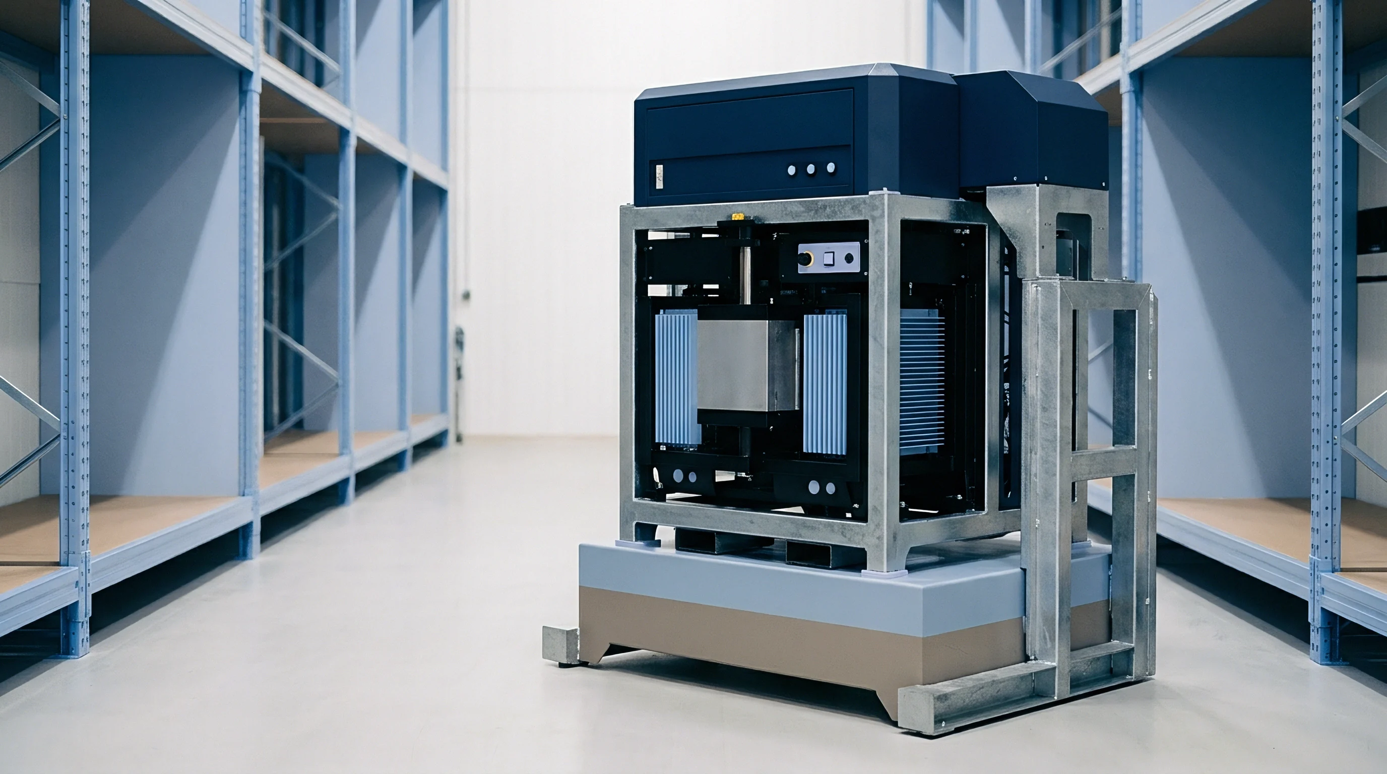
Micro-CT scanning provides non-destructive 3D imaging of internal stack deformation, separator buckling, and casing cracks without disturbing internal stresses. Warranty terms should explicitly designate micro-CT density maps as primary, legally binding evidence in technical arbitration.
Financial Liability Limits and Field Recall Triggers
Managing financial exposure means balancing liability caps against systemic defect risk. Cell manufacturers usually push to cap liability at 100 percent of annual cell purchase value. But a structural failure forcing a fleet recall can easily cost five to ten times the cost of the raw cells once labor, transport, replacement housings, and brand damage are factored in.
Negotiating balanced warranty covenants involves setting tiered defect rate thresholds:
- Standard epidemic failure threshold set at a 1.5 percent cumulative failure rate, triggering mandatory supplier technical support, expedited root-cause analysis, and replacement inventory at no cost.
- Severe structural recall trigger set at a 3.5 percent cumulative failure rate, giving the buyer authority to stop vehicle shipments, execute field recalls, and bill all campaign costs back to the cell vendor.
- Catastrophic structural failure clause covering thermal runaway driven by debonding or cell crushing, bypassing liability caps to demand full indemnification for consequential damages.
Clear financial covenants turn mechanical engineering metrics into binding commercial terms. Grounding warranty language in verifiable force, displacement, shear, and strain figures creates a practical, transparent framework for high-volume battery procurement.
Including pre-agreed telemetry formats and micro-CT teardown protocols directly in the supply agreement lets engineering teams resolve mechanical warranty claims quickly on physical facts rather than through endless legal negotiation.