Determining Initial Mechanical Preload Force for Prismatic Cells
Initial mechanical preload for prismatic cells is determined by calculating target surface pressure across active face area to prevent electrode delamination while absorbing swelling.

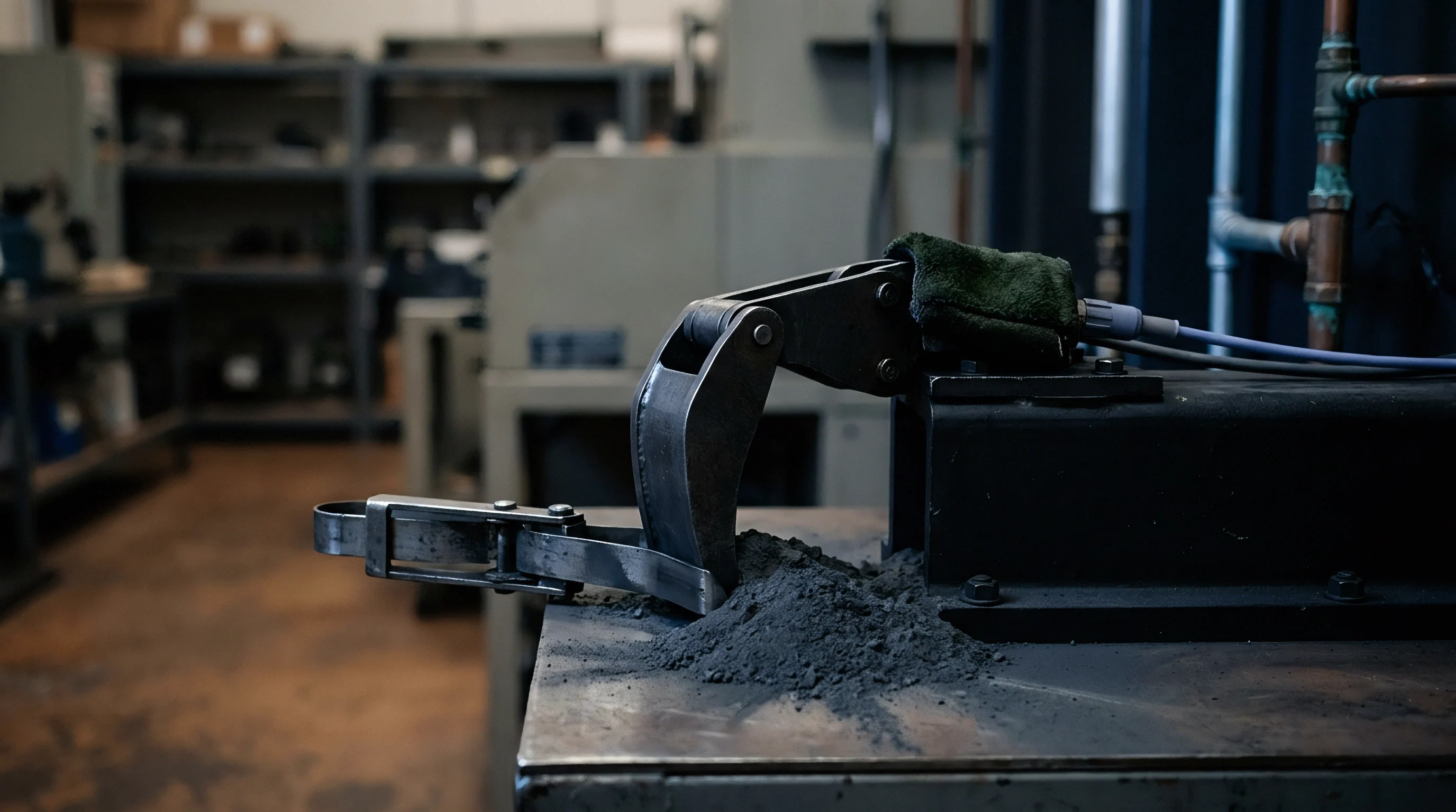
Clamp
A 280Ah lithium iron phosphate cell cycling at 1C expands by 1.8 percent of its overall thickness over 3,000 cycles. When unyielding steel end-plates hold a stack rigid, internal forces exceed 15 kilonewtons. Electrodes experience structural degradation when swelling goes unconstrained.
Gas accumulation between pouch layers and solid electrolyte interphase thickening drive non-uniform face pressure. Applying a target mechanical load retains intimate contact across active layers while accommodating dimensional growth over operational life.

Reversible Intercalation and Structural Expansion Dynamics
Electrode thickness increases during charging as lithium ions enter the graphite lattice. At the particle level, crystallographic expansion reaches approximately ten percent along the c-axis of carbon anodes. Macroscopic cell thickness variations remain smaller, typically fluctuating between two and four percent during full state-of-charge swings.
Reversible breathing occurs during every charge-discharge cycle. Irreversible swelling accumulates gradually across thousands of cycles due to parasitic electrolyte decomposition and transition metal dissolution. Unconstrained breath patterns accelerate mechanical fatigue within separator pore networks.
Deflection of cell housings changes internal current density distributions. Low pressure regions develop higher contact resistance between current collectors and active coatings. Microscopic separation reduces local ionic conductivity.
Heavy surface pressure suppresses particle movement but increases localized stress concentrations at cell corners. Designing appropriate retaining hardware requires balancing initial retention against maximum end-of-life pressure limits.
A surface pressure of 0.3 megapascals applied at 50 percent state of charge preserves electrode contact without triggering separator collapse during peak lithium intercalation.

Target Initial Force Ranges for LFP and NMC Formats
Factory specifications state recommended surface pressure limits based on active material mechanics. Lithium iron phosphate formulations exhibit higher volumetric expansion rates than nickel manganese cobalt chemistries. Take a 280Ah LFP cell with broad-face dimensions of 173 millimeters width by 204 millimeters height, establishing a surface area of 35,292 square millimeters.
Target initial surface pressure is specified at 0.3 megapascals. The required compressive load calculation yields 0.3 newtons per square millimeter multiplied by 35,292 square millimeters, equaling 10,587.6 newtons. At end-of-life under 80 percent state of health, maximum allowable pressure reaches 1.0 megapascal, elevating total force against end-plates to 35.29 kilonewtons.
Silicon-graphite blend anodes swell faster. Lithium iron phosphate cells expand.
| Format & Chemistry | Nominal Capacity (Ah) | Surface Area (mm²) | Initial Preload Window (kPa) | EOL Swelling Pressure (MPa) |
|---|---|---|---|---|
| 280Ah LFP | 280 | 35,292 | 200 – 400 | 0.8 – 1.2 |
| 100Ah NMC 622 | 100 | 19,800 | 150 – 300 | 0.5 – 0.8 |
| 304Ah LFP | 304 | 36,400 | 250 – 450 | 1.0 – 1.4 |
| 50Ah NMC 811 | 50 | 12,500 | 100 – 250 | 0.4 – 0.7 |
Incorrect initial surface load calculation damages internal components. Excessive baseline compression crushes polyethylene separator membranes. Reduced membrane porosity hampers lithium ion transport through liquid electrolyte.
High initial forces lower cell thermal runoff thresholds under abusive conditions.
- Electrode Delamination Insufficient initial force permits microscopic gaps to form between active material coatings and current collector foils during discharge contraction.
- Separator Pore Collapse Excessive compressive force exceeding 1.5 megapascals crushes micro-porous polyethylene separators, causing internal micro-shorts and accelerated self-discharge.
- Lithium Plating Accumulation Non-uniform pressure profiles generate localized low-pressure zones where ionic resistance increases, driving metallic lithium deposition during fast charging.
- Housing Weld Rupture Over-constraining irreversible growth transfers excessive tensile stress to aluminum case corner welds, inducing hermetic seal failure.
Cell manufacturers frequently assert that physical swelling beyond initial factory testing falls outside warranty coverage if housing end-plates deflect by more than 0.5 millimeters under cyclic load.
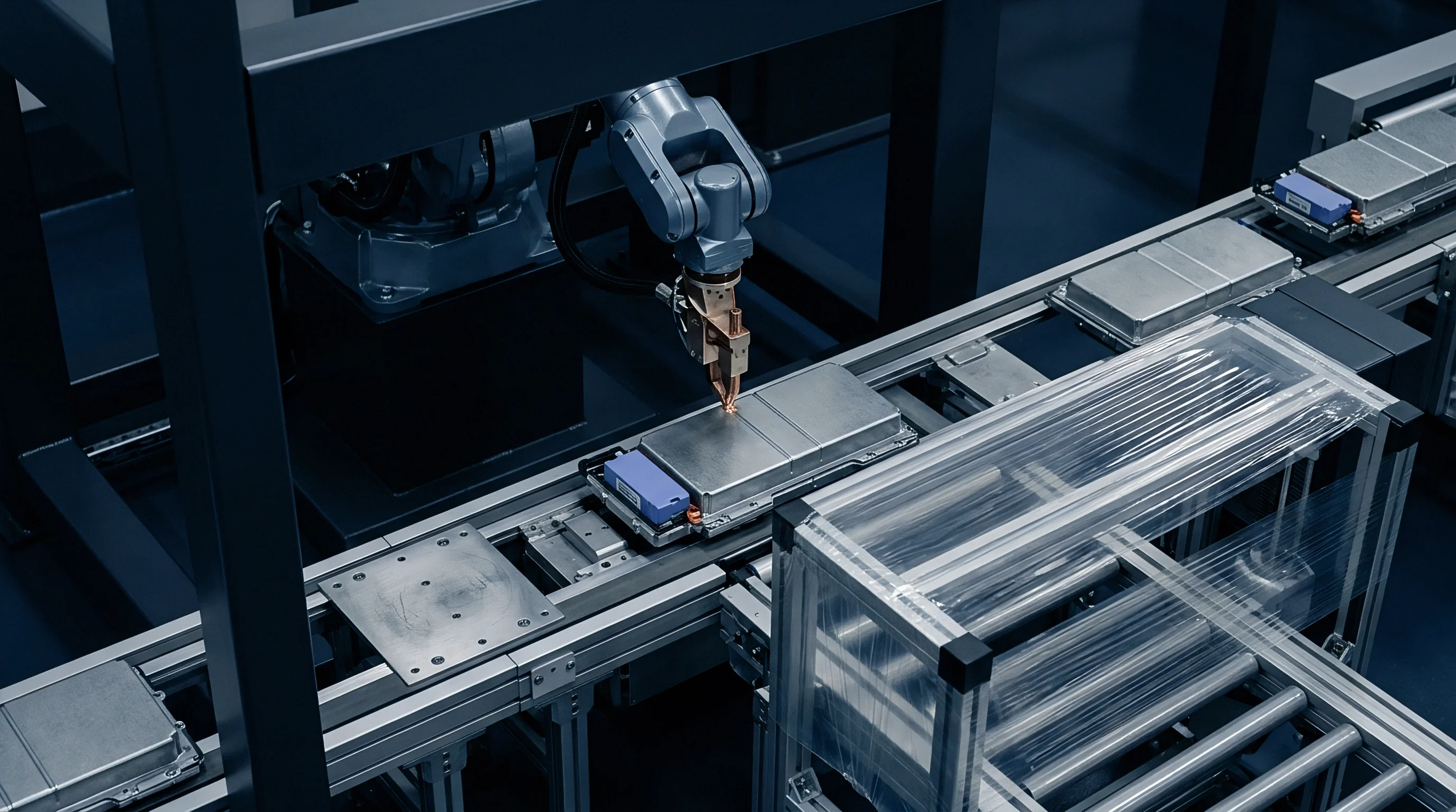

Foam
Compliance elements placed between adjacent cells absorb volumetric changes while maintaining mechanical integrity within the stack. Inserting elastomeric pads between broad cell faces converts rigid displacement into predictable spring compression. Polyurethane foams, silicone pads, and microcellular elastomers provide distinct stress-strain curves under static and dynamic compression.
Selecting appropriate compliance buffer thickness requires evaluating initial assembly compression alongside long-term stress relaxation profiles.

Elastic Deflection Characteristics of Interlayer Buffers
Polyurethane and silicone cushioning materials exhibit non-linear stress-strain curves under mechanical compression. Initial load application produces elastic deformation up to approximately 20 percent strain. Higher strain levels induce cell wall collapse within open-cell foam matrices, yielding a broad plateau where displacement increases without proportional pressure rises.
Solid microcellular elastomers exhibit immediate non-linear stiffness increases. Foam degrades over time. Springs maintain force.
Choosing soft foam causes excessive cell expansion under peak loads, while rigid pads transmit total swelling force directly to structural tie-rods.
| Buffer Material | Density (kg/m³) | Compression Set (50% Deflection, 70°C) | Long-Term Creep Retention (10 Years) | Thermal Conductivity (W/m·K) |
|---|---|---|---|---|
| Polyurethane Foam | 240 – 320 | 12% – 18% | 55% – 65% | 0.06 – 0.09 |
| Silicone Foam | 400 – 550 | 3% – 6% | 75% – 85% | 0.12 – 0.20 |
| Microcellular Elastomer | 500 – 650 | 5% – 8% | 70% – 80% | 0.15 – 0.25 |
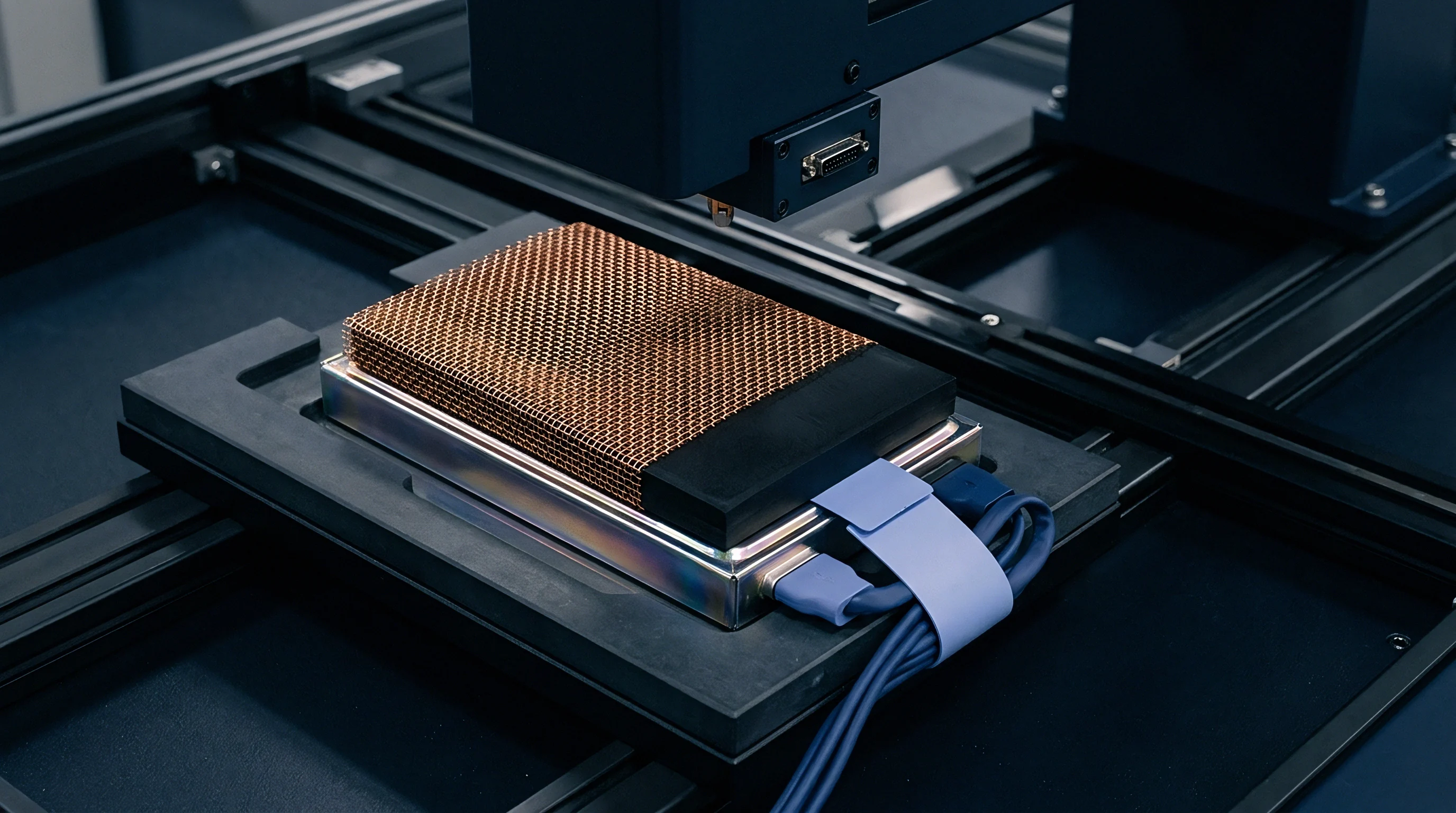
Viscoelastic Stress Relaxation and Creep Losses
Polymer matrices lose retaining force over prolonged exposure to static compression and elevated temperature. Viscoelastic stress relaxation reduces initial preload forces by 20 to 40 percent within the first year of storage. High ambient temperatures accelerate polymer chain rearrangement.
Creep reduces retention. Design calculations account for long-term load decay to prevent stack loosening at low states of charge.
Softer compression pads accommodate cell breathing but allow excessive displacement under external shock loads.
Determining net stack deflection over extended operating lifespans involves sequential engineering calculations.
- Measure the initial uncompressed thickness of the interlayer buffer sheet using an optical comparator.
- Apply the calculated baseline assembly load to establish initial stack compression thickness.
- Calculate the thermal expansion coefficient offset for the maximum expected module operating temperature.
- Project the ten-year viscoelastic relaxation curve from 1,000-hour stress relaxation test data under 60°C conditions.
- Determine final residual retaining force at end-of-life by subtracting long-term creep loss from initial structural compression.
Matching the elastic stiffness of the inter-cell buffer to the irreversible swelling rate of the cell preserves structural containment across the entire operational lifespan.
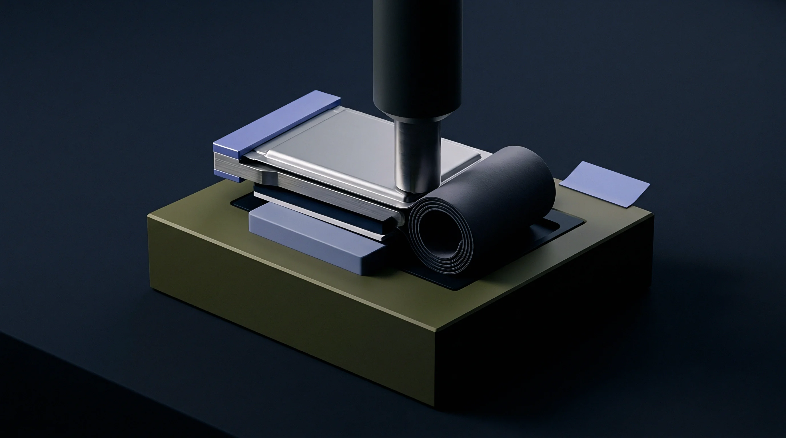
Strain
Multi-physics forces within a constrained stack fluctuate in response to temperature variations, charge rate, and accumulated operational aging. Thermal expansion of cell components interacts with mechanical constraint frames. Structural side plates and tie-rods undergo linear expansion, while internal cell layers expand nonlinearly under heat.
Operating modules across wide thermal windows shifts the internal force balance.

Thermal Expansion Coupling across Module Tie-Rods
Aluminum cell casings expand at a thermal expansion coefficient of 23 microstrain per degree Celsius, contrasting with steel side plates at 12 microstrain. Temperature increases generate differential expansion between internal cell rolls, outer casings, and external tension straps. High temperatures increase force.
Aluminum expands rapidly. Pressure surges at high temperature. Fast charging accelerates swell.
Steel tie-rods resist growth. Pressure spikes during rapid charge cycles combine thermal growth with peak lithium intercalation volume. Mechanical tie-rod strain gauges record dynamic load spikes exceeding static initial targets by up to 300 percent during 2C fast-charging protocols at 45°C ambient conditions.
Is Initial Preload Retention Preserved at Subzero Temperatures?
Freezing ambient conditions alter both structural cell casing dimensions and polymer compression sheet compliance. Cold shifts mechanical equilibrium. Cell materials contract at low temperatures, while elastomer buffer pads experience cold stiffening.
Glass transition behavior increases polymer modulus at subzero temperatures. Cells contract in freezing storage. Reduced cell volume combined with stiffened inter-cell buffers lowers residual retaining force on electrode stacks.
Storage at subzero temperatures reduces face pressure below minimum threshold limits, leaving internal jelly-rolls vulnerable to relative displacement under shipping vibration.
Whether active thermal management systems can completely offset subzero compression losses remains an open design question for winter operations.


Rig
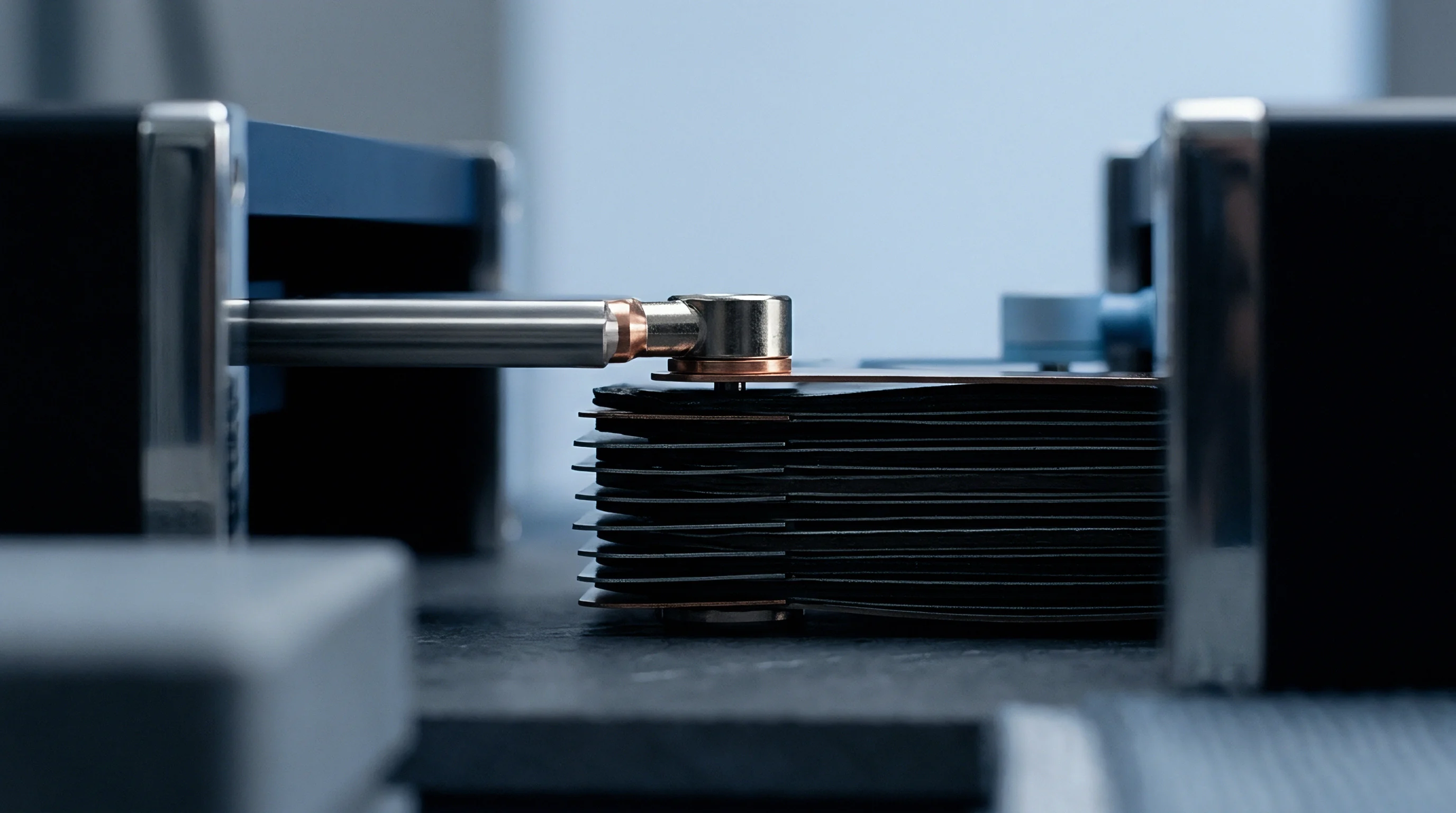
Bench verification requires precise load measurement fixtures capable of capturing surface pressure mapping without structural deflection. Standard laboratory test benches utilize heavy tool-steel end-plates held by calibrated tie-rods with inline load cells. Measuring total force alone fails to uncover non-uniform pressure distributions across wide prismatic cell faces.
Local pressure concentrations near side walls or casing corners alter internal degradation rates.

Tactile Pressure Mapping and Load Cell Instrumentation
Piezoresistive array sheets placed between cell faces capture spatial force distributions with sub-millimeter resolution. Calibrated tactile pressure sensors record localized pressure peaks caused by internal electrode overlap or casing irregularities. Load cells mounted at tie-rod ends measure gross axial force, while matrix sensor sheets identify edge loading patterns.
Zero-point calibration accounts for initial fixture compliance. Thermal compensation loops prevent temperature-induced sensor drift during environmental chamber validation cycles.
Failure to record pressure uniformity across eight surface zones invalidates factory end-of-line verification under quality control standard IEC 62619.
Acceptance Calibration for In-Line Assembly Fixtures
Production line bolting tools incorporate load cell feedback loops to maintain tight assembly force bands. Tooling determines initial force. Friction holds the stack.
Automated compression presses apply prescribed displacement or force profiles prior to securing side plate fasteners. Verification procedures validate tool calibration daily using certified master load frames. Data defines the window.
- Load Cell Thermal Compensation Integrate active temperature sensors adjacent to force transducers to offset thermal zero-drift during thermal chamber testing.
- Sensor Matrix Spatial Resolution Select tactile pressure film arrays with at least four sensing points per square centimeter to detect localized edge pressure concentrations.
- Fixture Structural Rigidity Design test frame end-plates with structural steel thickness sufficient to limit bending deflection below 0.05 millimeters under maximum test load.
- Multi-Axis Alignment Verification Validate parallel alignment between press platens to prevent asymmetrical force application during stack compression.
Improper torque calibration during initial stack bolting leads to localized electrode delamination, causing premature capacity drop and unrecoverable warranty exposure.
Standard
International transport regulations and safety codes dictate rigid mechanical integrity mandates for battery modules entering international trade. Dangerous goods transportation standards mandate structural containment during transit shock and vibration. UN 38.3 testing evaluates battery modules under severe mechanical stress profiles.
Mechanical constraint integrity determines whether cell stacks maintain electrical isolation and physical stability during transport handling.

Transport Certification Testing under Vibration and Shock Load
UN 38.3 testing subjects battery packs to rigorous sinusoidal vibration and high-g mechanical impact schedules. Test T3 vibration sweeps frequency bands between 7 hertz and 200 hertz over three hours per axis. Low stack compression allows individual prismatic cells to shift within module frames.
Friction generated by loose cells abrades insulation films, creating short circuit risks. Test T4 mechanical shock applies 150g peak acceleration profiles to test structural retention. Inadequate stack compression leads to terminal busbar shearing under shock loads.
| Regulatory Code | Scope & Application | Mechanical Test Condition | Pass/Fail Structural Criterion |
|---|---|---|---|
| UN 38.3 T3 | Transport Safety | Sinusoidal sweep 7 Hz to 200 Hz for 3 hours per axis | No mass loss, no rupture, force drop <10% |
| UN 38.3 T4 | Transport Safety | 150g peak acceleration, 6ms half-sine shock profile | Structural integrity maintained, zero containment breach |
| IEC 62619 Cl. 7.2 | Industrial Storage | 100 kN static crush test across long and short axes | Fire-free containment, module mechanical retention intact |
| UL 2580 | EV Pack Safety | Drop impact, compression load, and vibration sequence | Frame integrity preserved, no loose cell movement |

Regulatory Provisions for Module Structural Containment
Harmonized industrial mandates require battery enclosures to maintain structural containment under external crush forces. Harmonized EU Battery Regulation 2023/1542 mandates performance and durability verification across product lifespans. Test summaries carry documented initial compression forces alongside structural design filings.
Submitting incomplete mechanical verification files stops dangerous goods certification at border entry points.
Vibration testing according to UN 38.3 T3 induces fretting corrosion at terminal connections when stack constraint force falls below minimum tolerance limits.
- Vibration Frequency Sweeps UN 38.3 T3 test protocols require monitoring structural resonance shifts caused by internal stack loosening.
- Mechanical Shock Impact Profiles Test T4 mandates six half-sine shock pulses per axis to verify module retention structures stay within displacement limits.
- Industrial Safety Conformance IEC 62619 Clause 7.2 dictates evaluation of mechanical stress limits under simulated internal short circuit conditions.
- Transport Documentation Verification Shipper declarations must include UN 38.3 Test Summary reports identifying tested module constraint parameters.
Section 38.3.4.4 of the UN Manual of Tests and Criteria mandates that external mechanical containment structures remain fully intact post-impact, shifting non-compliance risk directly to the pack assembler of record.


Contract
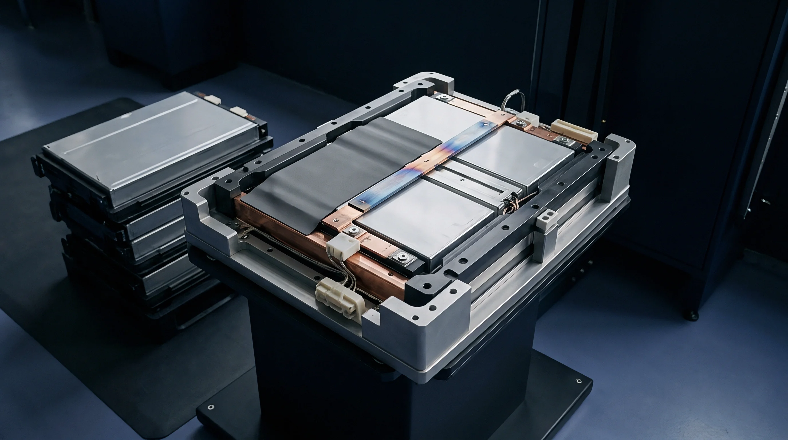
Commercial supply agreements define mechanical boundary conditions to establish unambiguous warranty responsibility. Cell datasheets specify nominal surface pressure limits and maximum allowable end-of-life forces. Pack integrators must design module structures that remain within vendor-specified force envelopes.
Ambiguous mechanical specifications lead to disputed warranty claims when cells exhibit premature capacity fade or localized pouch swelling.
Allocation of Mechanical Degradation Risk in Buyer RFQs
Request for quotation documentation incorporates detailed force window limits to protect buyers against cell degradation claims. Purchasing agreements define exact initial clamping pressure conditions, allowable end-of-life end-plate deflection, and maximum allowable operating surface pressure. Specifying rigid structural parameters prevents suppliers from blaming capacity loss on improper pack assembly.
Procurement files capture signed engineering boundary drawings signed by both cell supplier and module pack integrator.

Warranty Thresholds for Maximum End-of-Life Expansion
Supply terms establish clear swelling limits expressed as maximum allowable load under defined SOH thresholds. If cells exceed specified swelling pressures prior to reaching warranty cycle targets, liability rests with the cell manufacturer. If module end-plates deflect beyond contract tolerances, financial responsibility shifts to the pack packager.
Detailed landed-cost calculations incorporate warranty risk reserve funds mapped directly to mechanical stack stability metrics.
Legal disputes over battery performance routinely trace back to unverified initial mechanical assembly conditions. Establishing documented initial force records during factory assembly provides objective evidence for resolving commercial claims. Importers of record maintain verified mechanical inspection files alongside transport safety documentation to protect capital commitments across long production runs.