Thermo-Mechanical FEA Optimization for Structural Battery Enclosure Die Cooling Circuits
Coupling transient CFD convective flux with non-linear elastoplastic FEA prevents thermomechanical fatigue leaks across integrated structural battery cooling channels.

Chill
Heat generation within cell blocks during 3C fast-charging sequences or sustained high-rate discharge drives severe localized thermal gradients across structural battery enclosure floors. Modern cell-to-pack architectures position prismatic or large-format pouch modules directly onto integrated liquid-cooling channels embedded inside high-pressure die-cast aluminum structures. The fluid layer extracts heat across the contact interface while simultaneously supporting mechanical shear, bending, and torsional forces transmitted through the vehicle chassis.
Coupling transient fluid dynamics with continuous solid mechanics demands exact tracking of surface heat transfer coefficients alongside fluid pressure field distribution.
Coolant entering channels at 25 kPa to 350 kPa gauge pressure exerts internal hydrostatic wall forces that flex thin-walled heat-exchanger passages outward. Concurrently, localized temperature peaks reaching 75°C create localized compressive thermal stresses where hot channel sections expansion is constrained by colder surrounding rib networks. The resulting multi-axial stress field combines static hydraulic tensile load with cyclic thermal strain.
In dynamic structural enclosures, mechanical road inputs from wheel impacts introduce bending moments that superimpose on these thermal-hydraulic baseline states.
Ethylene glycol water mixtures at forty-sixty ratios under elevated temperature exhibit reduced viscosity that alters wall boundary layer shear without dampening structural hydraulic hammer during rapid pump cycling.
Structural die-cooling circuit walls typically measure between 1.5 mm and 2.5 mm in thickness to minimize thermal resistance and casting mass. Lower wall thickness reduces the conduction resistance through the aluminum housing. Thinner walls deform under internal hydraulic pressure, altering local channel cross-sectional areas.
A three percent channel deformation shifts fluid velocity profiles, triggering local flow recirculation zones. Recirculation reduces the localized convective heat transfer coefficient from 3,500 W/m²K down to 1,100 W/m²K. Lower heat removal accelerates local battery cell degradation, creating thermal runaway vulnerabilities in high-energy density packs.
Conjugate heat transfer models must capture fluid boundary layer behavior alongside thermal conduction within solid cast structures. Linear static mechanical analysis fails because thermal expansion coefficients for cast aluminum alloys change non-linearly above 80°C. Temperature-dependent yield strength degradation degrades structural margin during rapid cold-weather warm-up cycles when the fluid inlet operates at 60°C while the outer chassis perimeter remains clamped at -20°C. Structural FEA workflows must explicitly pass convective boundary conditions from fluid solvers directly into non-linear stress solvers.
Whether transient mechanical shocks from extreme suspension travel cause localized coolant leakage before material yield strain limits are reached across cast channel boundaries remains uncertain.

Mesh
Discretization strategies determine numerical stability and solution convergence when solving coupled thermo-mechanical stress fields across complex cooling passage geometries. Spatial meshing for fluid regions requires boundary-layer refinement with prism elements to capture velocity and thermal boundary layers. Solid structural domains demand second-order quadratic tetrahedral (C3D10M) or hex-dominated continuum elements (C3D8R) capable of modeling non-linear plastic deformation without shear locking.
Spatial node alignment at the fluid-solid boundary governs energy conservation during transient data transfers between CFD and FEA solvers.
High-Pressure Die-Cast (HPDC) aluminum alloys used in structural enclosures, such as AlSi10Mg and AlSi7Mg, demonstrate mechanical behavior dependent on temperature and processing history. Cast microstructures contain spatial variations in secondary dendrite arm spacing along with microscopic gas porosity. Solid elements in high-stress cooling channel corners require constitutive material definitions incorporating temperature-dependent elastoplasticity and modified kinematic hardening models.
Material properties degrade elevated thermal regimes, requiring non-linear stress-strain inputs spanning the full operating range.
| Alloy Condition | Temperature (°C) | Elastic Modulus (GPa) | Yield Strength (MPa) | Thermal Conductivity (W/m·K) | CTE (10⁻⁶/K) |
|---|---|---|---|---|---|
| AlSi10Mg As-Cast | -40 | 76.5 | 170 | 125 | 19.8 |
| AlSi10Mg As-Cast | 23 | 74.0 | 160 | 130 | 20.5 |
| AlSi10Mg As-Cast | 80 | 69.5 | 145 | 138 | 21.8 |
| AlSi10Mg As-Cast | 130 | 63.0 | 120 | 145 | 22.9 |
| AlSi7Mg T6 Heat Treated | 23 | 72.0 | 240 | 160 | 21.2 |
| AlSi7Mg T6 Heat Treated | 130 | 61.5 | 195 | 172 | 23.4 |
Thermomechanical mapping relies on strict transfer algorithms. Co-simulation methodologies pass transient nodal heat fluxes and pressure distributions between fluid and mechanical solvers at fixed temporal increments. Sequential mapping interpolation imports steady-state thermal fields as body loads into structural analyses.
Sequential mapping reduces computational overhead. It misses dynamic thermal shock transients during rapid load shifts.
- Fluid Mesh Boundary Discretization requires five prism layers along channel fluid walls with a first-layer dimensionless wall distance value below one to capture heat transfer gradients.
- Thermal-Mechanical Node Interpolation maps non-conformal fluid surface meshes to solid continuum structural nodes using spatial distance-weighted shape functions.
- Constitutive Stress Tensor Update applies temperature-dependent yield surfaces and modified Chaboche kinematic hardening rules at every integration point.
- Non-Linear Structural Solution Phase evaluates combined geometric non-linearity and thermal-expansion-induced strain using full Newton-Raphson iteration loops.
Non-conformal surface mesh boundaries require conservative flux interpolation algorithms to prevent false thermal strain concentrations along fluid-structure interface nodes.
Material yielding occurs rapidly near constrained channel corners. High localized stresses initiate low-cycle fatigue cracks after repeated thermal shock events. Linear elastic assumptions underestimate local plastic strain accumulation by up to forty percent in thin-walled cast cooling channels.
Incorporating cyclic plastic strain definitions allows precise fatigue life estimation using Coffin-Manson strain-life criteria.
Coarse structural meshes surrounding high-gradient thermal boundaries obscure localized plastic strain peaks.

Topology
Internal channel geometry optimization must simultaneously resolve competing thermal and mechanical demands. High convective heat transfer rates require narrow channels or dense internal pin-fin arrays that increase fluid velocity and mixing. These features restrict fluid flow, producing steep hydraulic pressure drops that elevate coolant pump electrical load.
Internal rib structures increase fluid-wetted surface area while acting as structural stiffeners that transfer bending and torsional loads across the vehicle battery tray floor.
Multi-objective optimization workflows use Solid Isotropic Material with Penalization (SIMP) or level-set topology techniques. The objective function penalizes thermal resistance and structural strain energy while imposing fluid pressure drop upper limits. Unrestricted topology optimization generates organic, highly complex flow passages.
These shapes often prove impossible to manufacture using conventional high-pressure die casting tooling without complex internal cores.
| Topology Type | Pressure Drop (kPa) | Nusselt Number | Torsional Stiffness Relative Index | Peak Von Mises Stress (MPa) |
|---|---|---|---|---|
| Parallel Smooth Ribs | 18.2 | 42.5 | 1.00 | 112 |
| Serpentine Channel | 64.5 | 88.0 | 0.82 | 148 |
| Staggered Pin-Fin Matrix | 48.1 | 115.2 | 1.18 | 135 |
| Manufacturable Topology-Optimized Branching | 27.4 | 96.8 | 1.34 | 89 |
A structural enclosure floor section measures 1,200 mm by 800 mm, subjected to a 35 kN torsional shear load from chassis twisting while extracting 12 kW of heat. A baseline serpentine channel design delivers required thermal heat extraction. The high fluid pressure drop requires 180 W of parasitic pump power.
The serpentine layout creates asymmetric stiffness across the enclosure floor, causing localized stress concentrations of 148 MPa along channel turn radii under torsional chassis load.
Replacing the serpentine path with a manufacturable topology-optimized branching structure changes stress distribution. Fluid pressure drop falls to 27.4 kPa, cutting pump electrical consumption. The branching ribs distribute mechanical load paths across the enclosure floor, lowering peak stress to 89 MPa.
Torsional stiffness increases by thirty-four percent over the baseline design, showing how optimized fluid layout enhances structural performance.
Ignoring thermomechanical stress coupling in channel optimization causes early structural housing failure. Rib structures designed solely for fluid flow can create rigid thermal constraints. Under rapid thermal expansion, these rigid zones generate internal bending moments that crack perimeter cast enclosure walls.
FEA optimization models must combine mechanical loading vectors directly with transient heat extraction routines.
Designing cooling channels without structural stress limits risks floor cracking under baseline chassis load.
Closure
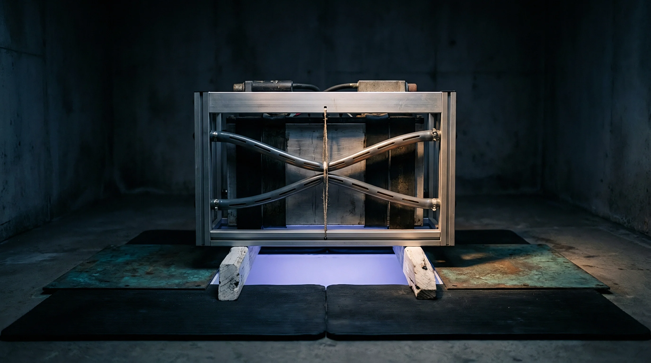
Translating optimized FEA channel layouts into physical battery enclosures requires matching geometric designs to casting and joining processes. High-Pressure Die Casting (HPDC) offers rapid cycle times and low unit costs for mass production. Standard HPDC cannot form internal hollow passages without specialized core technologies.
High internal cavity pressures during metal injection collapse conventional core materials. Soluble salt cores allow complex internal geometries, but residual salt traces inside cooling channels cause rapid fluid corrosion.
Manufacturers often cast open channel troughs on the enclosure floor, sealing them with an upper cover plate using Friction Stir Welding (FSW) or laser welding. Welding introduces intense localized heat input, triggering residual stress states and metallurgical phase changes across heat-affected zones. Laser weld seam profiles require careful finite element modeling to ensure joint integrity under combined internal fluid pressure and dynamic chassis flexure.
- Porosity Pore Expansion occurs when internal gas entrapment expands during laser welding thermal cycles, creating void micro-cracks across channel sealing boundaries.
- FSW Downward Tool Force Distortion causes permanent plastic bowing of internal channel rib walls, altering targeted coolant flow gaps.
- Thermal Shock Weld Seam Shear happens when temperature gradients between cover plates and cast bases concentrate shear strains along joint edges.
- Intermetallic Phase Precipitation reduces fracture toughness in heat-affected zones, lowering fatigue resistance under dynamic impact.

Where Do Weld Seams Shear under Thermal Shock?
Weld seam shear peaks at channel inlet manifolds, where cold entering fluid meets hot aluminum structures. Rapid localized thermal contraction draws cover plates inward, generating high peel and shear stress along perimeter weld seams. FEA models must incorporate temperature-dependent weld material properties and explicit weld bead profile geometry to predict joint life under combined thermal and pressure loading.
Physical verification demands burst testing and dynamic pressure cycle testing per ISO 16750-3 standards. Cold plates undergo 100,000 hydraulic pressure pulsation cycles from 30 kPa to 250 kPa at 80°C. Thermomechanical shock testing cycles fluid temperatures from -40°C to 85°C while subjecting the enclosure to 3G RMS random vibration inputs. Helium leak testing sets leak thresholds below 10⁻⁶ mbar·L/s to prevent glycol contamination inside live electrical cell compartments.
Foundry engineers frequently assert that casting micro-porosity levels within published ASTM standards will not compromise thin-walled channel hydraulic sealing under dynamic torsional fatigue.
Ownership
Specifying integrated die-cooling structural enclosures redefines commercial responsibility boundaries between tier-one foundries, pack integrators, and vehicle manufacturers. Tooling for large-format HPDC structural components requires significant capital investment, with multi-cavity dies and complex core slide mechanisms often exceeding two million dollars in Non-Recurring Engineering (NRE) costs. When FEA models fail to predict localized thermal fatigue, modifying hardened tool steel dies adds cost and extends launch timelines.
Contractual agreements must define quality control standards for internal channel integrity. Porosity classification under standards like VW 50097 or ASTM E155 must mandate strict radiological inspection criteria along internal cooling channel walls. A defect level accepted in external mounting brackets can cause fluid leakage or structural failure under fatigue loading when present in a 1.8 mm channel wall.
- Radiographic Inspection Bounds specify maximum allowable pore diameters within cooling passage walls, limiting gas inclusion sizes below 0.5 mm in high-stress zones.
- Burst Pressure Verification Rules require lot-sample testing to four times standard operating pressure without structural deformation or cover plate seam separation.
- Helium Leak Rate Seams assign strict financial liability to the casting finisher if post-machining residual stress relaxation causes fluid leakage above 10⁻⁶ mbar·L/s during production verification.
- Tooling Amortization and Modification Clauses designate who pays for die redesigns required when field test failures contradict thermal-mechanical FEA predictions.
Warranty risk allocation hinges on distinguishing structural mechanical fatigue from fluid-induced corrosion failure. If glycol coolant leaks onto high-voltage busbars, cell modules short-circuit, causing thermal runaway. The pack integrator blames internal casting porosity, while the foundry cites improper coolant corrosion inhibitor chemistry or unexpected chassis torsional inputs.
Explicit finite element stress validation criteria written directly into supply agreements provide objective technical metrics for arbitrating liability claims.
Supply contracts specifying that cast cooling enclosures must pass hydrostatic proof testing without defining concurrent thermomechanical strain limits leave integrators liable for field failures caused by combined thermal expansion and chassis dynamic twist.