Pouch Cell Swelling Force Measurement Protocols
Direct load frame measurement with sub-five-micron displacement control establishes pouch swelling force, isolating irreversible SEI growth from breathing.


Rig
Between ground steel platens torqued to forty Newton-meters, a 78 Ah nickel-manganese-cobalt pouch cell settles at an initial 0.25 MPa compressive pre-load. That mechanical baseline sets the zero point for every charge and discharge measurement that follows. Sourcing teams favour pouch cells because thin aluminum laminate packaging drives up gravimetric energy density, but eliminating a rigid outer case transfers the expansion loads straight onto module hardware.
As lithium ions cycle between electrodes, the host lattices expand and contract. Graphite expands roughly ten percent along its layers during intercalation, while silicon alloy particles swell up to three hundred percent at full lithiation. Left unrestrained, that volume swing delaminates coatings, shatters active particles, and pinches internal separators.
Capturing those mechanics requires an unyielding test rig. Cylindrical steel cans and aluminum prismatic cases provide their own structural containment, but a pouch cell on an open bench simply swells into free air, producing displacement figures that tell pack designers nothing about forces inside a constrained module. Test protocols generally follow one of two paths: constant gap or constant load.
A constant-gap rig locks platens at a fixed spacing to measure isometric swelling load as pressure builds against the tooling. A constant-load setup holds a set force with dead weights, pneumatics, or servo drives, tracking linear expansion as the pouch thickens. In either configuration, the fixture itself needs a structural stiffness well above one hundred kilonewtons per millimeter.
- Frame deflection errors corrupt load cell values when machine uprights bend under rising cyclic tonnage.
- Thermal platen drift introduces false expansion readings as ambient laboratory temperature swings distort test platens.
- Uneven torque distribution across tie-rod fasteners creates localized high-pressure bands that induce lithium plating during charge cycles.
- Transducer signal drift across six-month aging trials misrepresents continuous mechanical relaxation as permanent chemical decay.
Fixture compliance quickly corrupts test results. If an expanding cell sits in an undersized frame, the uprights can stretch twenty to fifty microns at full state of charge. That slight platen retreat allows the pouch to expand into the gap, registering an artificially low force on the load cell.
When those softened numbers feed into finite element models, structural designers spec module retaining walls that are far too thin. Months down the line, pack verification runs end with bowed end plates, crushed cooling fins, and sheared retention bolts.
Platen
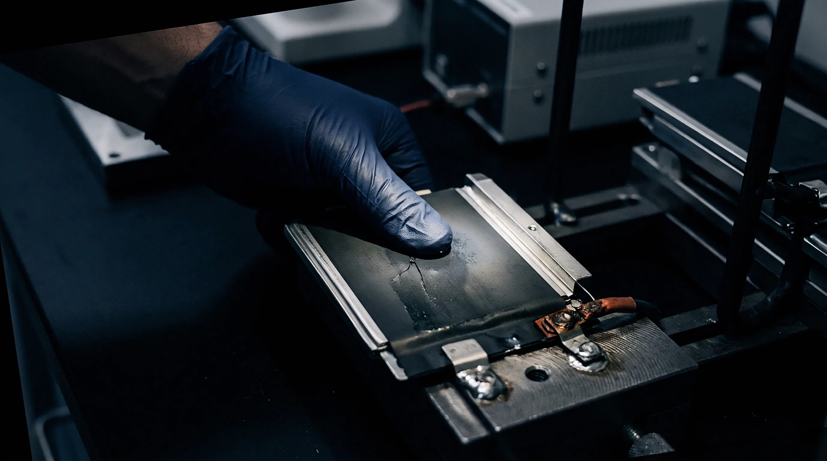
Tool-steel platens ground flat within ten microns spread clamping loads evenly across the active face of the pouch. Any crown, dish, or machining ripple disrupts contact pressure. Because current collectors route through the terminal tabs, resistive heating and chemical activity run hottest near the shoulders of the pouch.
If the platen lifts even slightly off the face, current concentrates into whatever patches maintain contact, accelerating localized degradation at those pinch points.
Sensor choice dictates whether an engineer sees localized stress spikes or just gross normal force. An inline canister load cell centered behind the platen reads total force in Newtons, which converts to an average swelling pressure in megapascals across the electrode area. That average hides edge and tab stress concentrations that routinely run three times higher than the mean reading.
Inserting piezoresistive pressure films between pouch and platen maps those localized peaks, though the thin sensor layers introduce compliance into the stack and require calibration so they do not cushion the rigid boundary condition.
A platen with ten microns of surface crown concentrates sixty percent of the compressive load across the pouch core.
Thermal control has to tie straight into the clamping plates. Pouch cells generate substantial resistive heat during 1C discharges, and massive steel platens pull that heat out unevenly unless temperature-controlled. Liquid-cooled plates with serpentine internal channels hold surface temperatures within one degree Celsius of setpoint through an entire run.
Without active fluid loops, the cold mass of the fixture chills the pouch exterior, creating through-thickness thermal gradients that skew both electrochemical kinetics and expansion behavior.
| Sensor Technology | Measurement Metric | Thickness Profile (mm) | Measurement Accuracy | Stiffness (kN/mm) |
|---|---|---|---|---|
| Inline Quartz Piezoelectric Load Cell | Aggregate Normal Force | 25.0 to 50.0 | ±0.1% Full Scale | > 250 |
| Piezoresistive Tactile Pressure Sheet | Spatial Pressure Distribution | 0.10 to 0.25 | ±4.0% Full Scale | 12 to 20 |
| Eddy-Current Displacement Sensor | Z-Axis Linear Expansion | Non-contact | ±0.5 µm | Infinite |
| Resistive Foil Strain Gauge Rosette | Fixture Tie-Rod Elongation | 0.05 to 0.10 | ±0.5% Reading | Matches Substrate |
Discrepancies in observed thickness typically trace back to specification sheets defining bare pouch dimensions under zero-pressure conditions rather than under external restraint.

Phase
Cell swelling splits into two concurrent mechanisms during cycling: reversible volumetric breathing and irreversible structural growth. Reversible breathing tracks lithium shuttling between electrodes. Charging graphite from zero to one hundred percent state of charge expands the anode lattice along its c-axis as lithium intercalates into the carbon layers.
Discharge reverses the lattice dilation, drawing the cell back toward baseline thickness. Irreversible swelling builds over hundreds of cycles as parasitic side reactions consume active lithium and permanently alter the electrode structure.
Electrolyte breakdown generates the solid electrolyte interphase on the negative electrode, thickening that passivating film with every thermal spike, high-voltage hold, and aggressive fast charge. Dense degradation byproducts choke the porous electrode network, lifting active material away from the copper foil and driving permanent volume expansion. Micro-cracking inside cathode particles accelerates the problem.
Layered high-nickel oxides contract anisotropically along individual unit cells during deep delithiation, generating internal stresses that crack polycrystalline grains. The fresh fracture surfaces expose unpassivated transition metals to acidic electrolyte components, sparking secondary reaction layers that permanently expand the cathode.
NMC811 pouch cells operating at 0.30 MPa initial compressive load exhibit a 1.2 MPa peak end-of-life swelling pressure after twelve hundred cycles at 1C.
A compressed cell stack exhibits viscoelastic relaxation much like an elastomer seal compressed in a subsea valve body. An initial 0.30 MPa clamping load creates an immediate elastic spike, followed by hours of decay as separators, binders, and porous coatings creep under load. When cycling starts up, dynamic swelling forces ride on top of this settling baseline.
Procurement contracts that overlook settling times before zero-point measurements guarantee disagreements between cell vendors and pack integration facilities.
- Initial mechanical stabilization verifies that separator creep subsides before cycling routines initiate.
- State of charge alignment synchronizes force data logging with cell open-circuit voltage plateaus.
- Active thickness tracking isolates elastic housing deformation from permanent active layer swelling.
- Gas release isolation distinguishes pouch envelope ballooning from solid-state electrode matrix expansion.
Disagreement continues over whether peak swelling loads originate mainly from graphite phase transitions in the anode or from concurrent phase shifts across high-nickel cathode materials during high-voltage operation.
Regime
Charge and discharge rates directly dictate peak instantaneous forces. Driving a cell at 2C or 3C forces lithium ions into the negative electrode faster than solid-state diffusion can distribute them through the graphite particles. Ions pile up near particle surfaces, establishing steep concentration gradients.
The outer shells of the graphite grains expand while the cores stay unlithiated, generating severe hoop stresses and exaggerating cell-level expansion. A load cell catches this as an abrupt force spike well above what appears during a slow C/10 charge to the exact same capacity.

How Do Dynamic Cycling Rates Distort Peak Force?
Pulse testing reveals pronounced mechanical hysteresis across charge and discharge curves. When swelling force is plotted against state of charge, the path forms an open loop where peak force lags peak electrical capacity. Diffusion bottlenecks delay the mechanical peak by fifteen to forty-five minutes behind electrical input.
During hard discharge, particle surfaces contract while cores remain expanded, producing lower instantaneous normal force than a static rest at the same state of charge would show. Getting clean baseline data requires a full sixty minutes of zero-current rest after charging to let chemical and mechanical stresses equilibrate.
Mechanical force logging without concurrent displacement tracking obscures whether pressure shifts stem from internal battery chemistry or load frame compliance.
Standards like IEC 62660-1 define electrical testing for secondary cells without specifying fixture stiffness. That leaves cell manufacturers free to publish cycle-life curves run under twenty-kilopascal foam pads, which cushion the delicate pouch seals from high compressive loads. In an automotive pack, however, those same cells sit clamped between rigid aluminum cooling plates under an initial assembly pressure of three hundred kilopascals.
A pouch rated for twelve hundred cycles under soft laboratory restraints may fail short of six hundred cycles inside a production housing.
| Cathode / Anode Chemistry | Nominal Capacity (Ah) | Initial Pre-load (MPa) | Reversible Breathing (Δ mm) | EOL Swelling Pressure (MPa) |
|---|---|---|---|---|
| NMC622 / Graphite | 60 | 0.20 | 0.28 ± 0.03 | 0.85 ± 0.08 |
| NMC811 / Graphite | 78 | 0.30 | 0.35 ± 0.04 | 1.25 ± 0.12 |
| NMC811 / Si-Graphite (10% Si) | 65 | 0.35 | 0.62 ± 0.06 | 1.85 ± 0.18 |
| LFP / Graphite | 50 | 0.25 | 0.18 ± 0.02 | 0.92 ± 0.09 |
| Values reflect 80% State of Health endpoint at 25°C, 1C/1C continuous cycling, 100 kN/mm frame stiffness. | ||||
Section 7.3 of typical automotive supply agreements dictates that cell warranty obligations terminate if module assembly boundary pressure exceeds supplier-defined maximum ratings at any point during vehicle operation.

Bulkhead
Translating test-bench curves into production hardware falls on module structural designers. A pack module stacking twenty-four pouch cells in series accumulates swelling force along its main axis. Bare pouches cannot sit face-to-face without risking insulation wear and localized stress points.
Designers interleave polyurethane or silicone foam pads between adjacent cells to solve two competing problems: the foam must retain enough resilience to maintain contact pressure during sub-zero operation early in life, yet stay compliant enough to absorb irreversible long-term expansion without overloading module bulkheads.
A stack of twenty-four 78 Ah NMC811 pouch cells illustrates the mechanical challenge. With each cell measuring 12.00 mm thick over an active area of 300 mm by 100 mm (0.030 m²), twenty-five microcellular polyurethane foam pads of 1.50 mm uncompressed thickness sit between cells and end bulkheads. Targeting an initial preload of 0.25 MPa across 0.030 m² requires 7,500 Newtons of clamping force.
The foam’s compression curve requires thirty percent strain to develop 0.25 MPa, compressing each sheet from 1.50 mm to 1.05 mm. That takes up 0.45 mm per pad across twenty-five positions, absorbing an initial 11.25 mm of stack space.
Where silicon additives amplify displacement, each pouch expands by five percent in irreversible thickness over eight hundred cycles to eighty percent state of health, adding 0.60 mm per cell. Across twenty-four cells, total growth reaches 14.40 mm. Assuming rigid tie-rods and infinitely stiff end plates, that 14.40 mm expansion forces the twenty-five foam pads down from 1.05 mm to 0.474 mm.
At sixty-eight percent compression, the foam reaches solid densification, where compressive modulus climbs steeply. Pushed into that regime, module internal pressure surges from 0.25 MPa to 1.65 MPa, driving a continuous 49,500 Newtons against the end plates.
- Calculate aggregate cell expansion by multiplying nominal cell thickness by verified irreversible expansion percentages across target cycle life.
- Select compression pad thickness and initial compression levels to place early-life operating pressure above the minimum threshold that prevents active material delamination.
- Simulate end plate bending deflection under peak end-of-life load to confirm tie-rod stresses remain below sixty percent of material tensile yield limits.
- Validate cooling interface integrity under maximum platen compression to verify thermal interface materials do not squeeze out of thermal paths.
To prevent unchecked displacement from crushing cooling fins, the module engineer balances end plate thickness against mass efficiency. Beefing up aluminum bulkheads from six millimeters to twelve millimeters keeps deflection under control, but the weight penalty cuts into pack energy density. Thinning the bulkhead invites the center to bow outward under load.
As the middle yields, pressure drops at the center of the stack while concentrating destructive compressive stress along the edges where tie-rods clamp the perimeter. Core cells delaminate and fade prematurely from insufficient pressure, while edge cells fail from torn separators and internal shorts.
A module bulkhead engineered with insufficient stiffness destroys the cells at its borders before the core reaches half its design life.


Seam
Pouch cells rely on heat and pressure to seal aluminum laminate foil around the internal electrode stack. That peripheral heat seal forms the mechanically weakest part of the entire cell. Under rigid platen constraints, incompressible liquid electrolyte pressurizes as active materials expand.
If core pressure exceeds the tensile strength of the polymer seal layer, the seam ruptures, releasing volatile carbonate solvents and conductive salts into the module cavity. Module assembly prints define strict clearance zones to keep clamping hardware from bearing on the seal flange.

Where Do Swelling Discrepancies Breach Supply Agreements?
Contract disputes frequently turn on whether swelling limits function as technical performance targets or as legal exclusions for warranty claims. Datasheets routinely specify nominal cell thickness with broad unilateral tolerances, such as twelve millimeters plus or minus 0.8 mm. Over thirty cells in a module, that variance allows stack height to wander by twenty-four millimeters before the first charge cycle ever runs.
If cells arrive at the thick end of the spec, assembly presses can over-compress the stack on day one, driving starting pressure well past design limits. Sourcing groups head this off by negotiating thickness sorting bins and binding mechanical interface control drawings.
Incoming cell lot rejection clauses remain unenforceable when purchase orders fail to cite specific load frame stiffness ratings and compression rates.
Receiving inspection stations run incoming sample cells through automated pneumatic test fixtures right on the dock. These fixtures perform baseline thickness scans under calibrated 0.20 MPa contact platens. Cells falling outside designated thickness bins are either flagged for return or sorted into matched-thickness assembly batches.
Matched sorting ensures balanced stacks, preventing thick cells from absorbing the brunt of assembly preload while neighboring thin cells sit loose in the frame.
Tooling outlays and quality gates determine which party absorbs financial risk across the supply chain. When procurement teams sign off on generic supplier expansion data without running independent multi-cell validation trials, the integrator absorbs the cost of downstream field failures. Expanding pouch cells generate continuous mechanical loads capable of warping cooling plates, splitting structural enclosures, and shearing wire-bonded interconnects.
Pinning down these forces through standardized mechanical testing before signing supply contracts protects warranty reserves and corporate balance sheets alike.